1
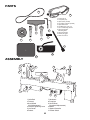
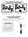
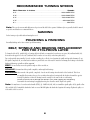
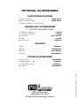
TurncrafterPro™
Variable Speed Lathe
User’s Manual
Read this manual completely before usage.
5
4
3
Model #TCLPROVS
9900 Global Rd.
Philadelphia ,PA. 19115
Version 2 – 10/06
SPECIFICATIONS
OF TURNCRAFTER™PROVS MIDI LATHE
Model number: . . . . . . . . . . . . . . . . . . . . . . . . . . . . . . . . . . . . .#TCLPROVS
Motor: . . . . . . . . . . . . . . . . . . . . . . . . . . . . . . . . . . . . . 1/2 HP, 120V AC, 8A
Variable speed: . . . . . . . . . . . . . . . . . . . . . . . . . . . . . . . . 650 to 3800 RPM
Distance between centers: . . . . . . . . . . . . . . . . . . . . . . . . . . . . . . . . . . . 18"
Distance between centers with extension bed: . . . . . . . . . . . . . . . . . . . 39"
Swing over bed: . . . . . . . . . . . . . . . . . . . . . . . . . . . . . . . . . . . . . . . . . . . 10"
Head stock spindle thread: . . . . . . . . . . . . . . . . . . . . . . . . . . . . . . . 1" x 8tpi
Hollow head stock . . . . . . . . . . . . . . . . . . . . . . . . . . . . . . . #2 Morse Taper
Hollow tail stock . . . . . . . . . . . . . . . . . . . . . . . . . . . . . . . . . #2 Morse Taper
Overall Size: . . . . . . . . . . . . . . . . . . . . . . . . . . . 30"L x 7-1/4" W x 14-1/2"H
Overall Size with extension bed: . . . . . . . . . . . . 54"L x 7-1/4" W x 14-1/2"H
Net weight (lathe only): . . . . . . . . . . . . . . . . . . . . . . . . . . . . . . . . . . . 71 lbs.
Net weight with extension bed: . . . . . . . . . . . . . . . . . . . . . . . . . . . . 90 lbs.
WARRANTY
THE TURNCRAFTERPROVS™ LATHE IS
WARRANTED AGAINST DEFECTS IN
MATERIALS AND WORKMANSHIP FOR A
PERIOD OF THREE (3) YEARS FROM THE DATE
OF PURCHASE. THIS WARRANTY APPLIES TO
THE PURCHASER OF THIS PRODUCT, AND IS
LIMITED TO THE REPAIR OR REPLACEMENT
OF THE PRODUCT OR ITS PARTS AT PSI
WOODWORKING PRODUCTS’ DISCRETION.
EXCLUDED ARE PARTS WHICH HAVE BEEN
MISUSED, ABUSED, ALTERED OR CONSUMED
BY NORMAL OPERATION OF THE MACHINE.
ALSO EXCLUDED ARE DIRECT OR
CONSEQUENTIAL DAMAGES TO PERSONS,
PROPERTY, AND/OR MATERIALS. YOUR
INVOICE SERVES AS PROOF OF PURCHASE
AND MUST BE REFERENCED PRIOR TO
RETURN AUTHORIZATION.
______________________________________________
DATE PURCHASED
2
__________________
INVOICE NO.
SAFETY INSTRUCTIONS
1.
Read and understand this instruction manual.
2.
NEVER connect plug to power source until all of the assembly steps have been completed.
3.
Check that your supply voltage and grounding are correct.
4.
Do not use the lathe in a damp or wet location.
5.
Keep lathe clean and lightly oiled.
6.
Make sure the belt, pulley, and control box are adequately guarded at all times.
7.
Always remove any tools, chuck keys, toggle bars, etc. when you are finished with them.
8.
Keep the work area well lit and provide adequate ventilation and workspace.
9.
Keep young children and bystanders at a safe distance from the lathe.
10.
Do not force the lathe to do more than what it is designed to do.
11.
Do not wear loose clothing, jewelry, or neckties which could get caught in revolving parts. It is recommended that long hair be
restrained.
12.
Safety eye wear should be worn at all times. Also, it is recommended to a use of face or dust mask during lathe operation.
13.
Attach all workpieces securely to the lathe, whether between centers, on face plates, or in chucks, etc.
14.
For best results be sure to keep turning tools sharp, clean, and free from rust.
15.
Use only three wire extension cords that have 3-prong grounding type plugs and 3-hole receptacles that accept the tool's plug.
16.
Check the speed BEFORE mounting any material onto the lathe. ALWAYS start the lathe at a slow speed.
17.
Keep the door to the pulleys and belts securely screwed closed during lathe operation.
3
PARTS
5
10
1. Toolrest (6 in)
2. Faceplate (3 in)
3. Spur Center (#2 MT)
4. Live Tailsock Center (#2 MT)
5. Spare Drive Belt
6. Hex Wrenches (set of 2)
7. Set of 4 Mounting Screws
8. Speed Controller
Mounting Plate
9. Speed Controller
10. Safety Goggles
11. Knock-out Rod
6
2
7
4
3
1
11
9
8
ASSEMBLY
8
9
5
3
4
7
6
2
1
10
11
1 Lathe Bed
2 Tailstock
3 Hand Wheel
(Quill Adjustement)
4 Tailstock Tightening Lever
5 Live Center
6 Toolrest
4
12
7 Headstock
8 Faceplate
9 Hand Wheel
(Headstock Adjustement)
10 Motor
11 Speed Controller
12 Power Switch
MULTI-POSITIONING CONTROL BOX
FOR THE #TCLPROVS LATHE
m The control box for the TCLPROVS is easily mounted
on the bottom of the bed. This is completed by using the
screws that also mount it to the rear of the bed and using
the provided mounting plate.
m The control box for the TCLPROVS can also be easily
mounted anywhere that is convenient for you. The 3' cord
from the motor to the control box allows you that flexibility.
MOUNTING AND CHANGING
THE SPEED CONTROL
We have packed the speed cotrol box separately to prevent damage. Unpack the speed control box and mount on to the back of the
headstock below the hinge under the hand wheel (the control box can be mounted elsewhere, mounting screws and washers
included). Once mounting is complete, connect to the plug of the control box to the plug of the motor.
The TCLPROVS is fitted with a 3-step pulley set-up which allows for the ranges of speed. See Speed Chart below.
Speed Chart
CHANGING
THE BELT POSITION
Make sure that the lathe is turned off or unplugged. Open the belt
door on the headstock. Loosen the ratchet handle to allow the
motor plate to swivel upwards. Swing the control box to the side
for access to the motor pulley. To change the speed move the belt
drive from one pulley to another. (NOTE: Always go from
the larger pulley to the smaller pulley) After moving
the belt, move down and tighten the motor pulley with the
ratchet handle– this also tightens the belt. Turn your lathe's
power on, and make sure that the belt is running consistently in
its parallel groove. If all is smooth, turn the power off, reattach
the control box and the belt door to its original position
5
A= 650-1430 RPM
Headstock
Pulley
B= 1240-2790 RPM
C= 1600-3800 RPM
C
A
Motor
Pulley
B
RECOMMENDED TURNING SPEEDS
Work Diameter in Inches . . . . . . . . . . . . . . . . . . . . . . . . . . . . . . . . . Speeds
0-2" . . . . . . . . . . . . . . . . . . . . . . . . . . . . . . . . . . . . . . . . . . . . . 2600-3800 RPM
2"-3" . . . . . . . . . . . . . . . . . . . . . . . . . . . . . . . . . . . . . . . . . . . . . 2000-2600 RPM
3"-4" . . . . . . . . . . . . . . . . . . . . . . . . . . . . . . . . . . . . . . . . . . . . . 1300-2000 RPM
4"-5" . . . . . . . . . . . . . . . . . . . . . . . . . . . . . . . . . . . . . . . . . . . . . . 650-1300 RPM
6"+ . . . . . . . . . . . . . . . . . . . . . . . . . . . . . . . . . . . . . . . . . . . . . . . . . . . . 650 RPM
Note: These speeds can vary with different wood species and the skill of the operator. Unbalanced pieces generally should be turned
on speeds lower than those recommended above.
SANDING
Use the fastest speed possible without burning the wood.
POLISHING & FINISHING
Generally finishing can be done at faster speeds than turning.
BELT, SPINDLE AND BEARING REPLACEMENT
FOR THE #TCLPROVS LATHE
To change the belt (#53), spindle (#14), or bearings (#4) for the lathe, you must first loosen the two set screws (#2) and hand wheel (#1).
Next remove the upper access door (#7) and knob (#8) loosen the set screw (#69) on the drive pulley (#25).
Tap out the spindle using a mallet. If you do not have a mallet, place a block of wood against the spindle and tap with a hammer. To get
the spindle completely out, use a flat head screwdriver to punch it the rest of the way. Be careful not to damage the bearings or the threads.
Replace the bearings, spindle or belt as required.
BELT: You need only to move the spindle enough to slide a new belt on.
SPINDLE: You must knock the spindle completely out through both bearings.
BEARINGS: After removal of the spindle, completely – knock out the bearings from the inside of the headstock. This is best
accomplished by inserting a long rod or screwdriver through one bearing inside the headstock toward the opposite
bearing. Tap firmly to remove the bearing from the casting. Do the same for the second bearing.
Please be aware not to damage the retainers (#13) when tapping out the bearing.
Reassemble the new bearings by tapping them into place from the outside. Replace the spindle.
Note: You may have to loosen the ratchet handle (ZTCL3-33 - PARTS #44, #45, #46) to reinstall the spindle pulley (#52), spindle collar
(#3), and belt (#53). Reinstall the hand wheel and set screws. DO NOT tighten the hand wheel against the bearings. Tighten the pulley set
screw and close the access door.
6
PARTS LIST
1
2
3
4
5
6
7
8
9
10
11
12
13
14
15
16
17
18
19
20
21
22
23
24
25
26
27
28
29
30
31
32
33
34
37
38
39
40
41
42
43
44
45
46
47
48
49
50
51
52
53
54
55
56
57
58
59
60
61
62
63
64
65
66
67
68
69
70
71
72
ZTCL3-22
HAND WHEEL
ZTCL3-28
HEX SOCKET SCREW M6_12
ZTCL4-03
COLLAR SPINDLE
ZTCL4-04
BALL BEARING 80105
ZTCL4-05
HEX SOCKET SCREW M8_25
ZTCL4-06
WASHER
ZTCL4-07
REAR BELT DOOR
ZTCL4-08
MOVING KNOB
ZTCL4-09
STATIONARY KNOB
ZTCL4-10
BOLT
ZTCL4-11
SEMI-CIRCLE HEAD SCREW
ZTCL4-12
HEADSTOCK CASTING
ZTCL4-13
RETAINING RING 47
ZTCL4-14
HEADSTOCK SPINDLE
ZTCL3-13
FACE PLATE
ZTCL3-12
HEADSTOCK SPUR CENTER
ZTCL3-40
LOCK HANDLE FOR TOOL REST BASE
ZTCL3-34
RETAINING RING 10
PART OF ZTCL3-36 - TOOL REST BUSHING
ZTCL3-35
TOOL REST
ZTCL3-36
TOOL REST BASE
ZTCL3-37
TOOL REST CAM FOLLOWER
ZTCL4-23
BOLT
ZTCL4-24
SPRING WASHER
ZTCL3-06
ZTCL4-25
SPRING WASHER
ZTCL4-26
LOCK BOLT
ZTCL3-11
CUP CENTER
ZTCL3-LS
ZTCL3-10
BALL BEARING 80102
ZTCL3-09
TAPER ROD
ZTCL3-08A
TAILSTOCK QUILL
ZTCL3-08B
TAILSTOCK OPERATING SCREW
ZTCL3-05
TAILSTOCK
ZTCL3-07
ECCENTRIC AXIS
ZTCL3-04
QUILL ADJUSTING WHEEL
ZTCL3-42
CAM FOLLOWER TAILSTOCK
ZTCL4-38
HOLDDOWN ADJUSTER TAILS
ZTCL3-03
RETAINING PLATE
ZTCL3-02
HEX SOCKET SCREW M10_12
ZTCL3-43
LOCK PLATE
ZTCL3-39
NUT M10
ZTCL4-43
FLAT HEAD SCREW
ZTCL4-44
SPRING WASHER
ZTCL3-33
ZTCL4-45
RATCHET HANDLE
ZTCL4-46
LOCK SCREW
ZTCL3-30
HEX SOCKET SCREW M8_12
ZTCL4-48
MOTOR PLATE WITH NOTCH
ZTCL4-49
BIG WASHER
ZTCL4-50
WASHER 6
ZTCL4-51
MOTOR PULLEY
ZTCL4-52
DRIVE PULLEY
ZTCL3-26
DRIVE BELT
ZTCL4-54
BOLT
ZTCL4-55
WASHER
ZTCL4-56
DOOR LATCH
ZTCL4-57
WASHER 4
ZTCL4-58
HINGE
ZTCL4-59
SEMI-CIRCLE HEAD SCREW M4_8
ZTCL4-60
SWITCH-BOX PLATE
ZTCL4-61
PIN HINGE
ZTCL4-62
POWER CORD
ZTCL4-63
OVERLOAD PROTECTOR
ZTCL4-64
LINE BOARD
ZTCL4-65
SEMI-CIRCLE HEAD SCREW M4_6
ZTCL4-66
SWITCH-BOX
ZTCL4-67K
KNOB
ZTCL4-68
SWITCH
ZTCL4-69
HEX SOCKET TAPER SCREW M6_12
ZTCL4-70
MOTOR
ZTCL3-50
RUBBER WASHER
ZTCL3-43
NUT M10
}
}
}
1
2
4
6
1
1
1
1
1
1
2
1
1
1
1
3
1
1
1
1
2
2
2
2
1
1
1
1
1
1
1
1
1
1
1
2
2
2
1
1
1
1
1
1
3
3
1
1
1
1
1
1
1
2
2
2
1
1
1
1
4
1
1
1
4
1
4
4
73
74
75
76
77
78
67
79
80
ZTCL3-53
ZTCL4-74
ZTCL3-51
ZTCL4-76
ZTCL4-77
ZTCL4-78
ZTCL4-67R
ZTCL4-79
ZTCL4-80
RETAINING RING
WASHER
8MM FENDER WASHER
FLAT HEAD SCREW
BRUSH CAP
MOTOR BRUSHING
SPEED RHEOSTAT
KNOCK OUT BAR
CONTROLLER TO MOTOR CORD
1
4
1
3
2
2
1
1
1
OPTIONAL ACCESSORIES
DUPLICATING SYSTEM
PSI duplicator attachment . . . . . . . . . . . . . . . . . . . . . . . . . . . . . . . #CML-DUPJ
Optional 2-ended carbide cutter . . . . . . . . . . . . . . . . . . . . . . . . . . #CML-DUPX
Steel duplicator templates for a variety of projects.
HEADSTOCK ACCESSORIES
(1" X 8TPI OR #2 MORSE TAPER)
3/8" Drill chuck- #2 MT mount . . . . . . . . . . . . . . . . . . . . . . . . . . . . . . . . . .#TM22
1/2" Drill chuck- #2 MT mount . . . . . . . . . . . . . . . . . . . . . . . . . . . . . . . . . #TM32
Mini screw chuck . . . . . . . . . . . . . . . . . . . . . . . . . . . . . . . . . . . . . #PK-TOP-MJ
Chisel Mate . . . . . . . . . . . . . . . . . . . . . . . . . . . . . . . . . . . . . . . . . . . . . . . . . . #LCM5
4-Piece Drive Center . . . . . . . . . . . . . . . . . . . . . . . . . . . . . . . . . . . . . . . . #LCENT4
CHUCKS
MinIGrip . . . . . . . . . . . . . . . . . . . . . . . . . . . . . . . . . . . . . . . . . . . . . . . . . #CMG3C
Utility Grip . . . . . . . . . . . . . . . . . . . . . . . . . . . . . . . . . . . . . . . . . . . #CUG3418C
Barracuda . . . . . . . . . . . . . . . . . . . . . . . . . . . . . . . . . . . . . . . . . . . #CSC2000C
Barracuda2 . . . . . . . . . . . . . . . . . . . . . . . . . . . . . . . . . . . . . . . . . . #CSC3000C
OTHER ACCESSORIES
9900 Global Road
Philadelphia, PA 19115
© 2006 PSI Woodworking Products
TurnCrafterPro™ Lathe #TCLPROVS - V2 - 10/06
Dust collection hood . . . . . . . . . . . . . . . . . . . . . . . . . . . . . . . . . . . . #DLHOODC
Pen making mandrel- 1" x 8tpi . . . . . . . . . . . . . . . . . . . . . . . . . . . . . . #PKM-BL
Pen making mandrel- #2 MT . . . . . . . . . . . . . . . . . . . . . . . . . . . . . . #PKM-FLC
Extension bed . . . . . . . . . . . . . . . . . . . . . . . . . . . . . . . . . . . . . . . . . #TCLPROXB