1
SIERRA VIDEO SYSTEMS
Crestron E-Server 908012
User’s Manual
UM908012-01
CRESTRON E-SERVER
User’s Manual
Sierra Video Systems
P.O. Box 2462 Grass Valley, CA 95945
Tel: (530) 478-1000
Fax: (530) 478-1105
Email: info@sierravideo.com
Version 3.0
Publication Date: February 2012
The information contained in this manual is subject to change by Sierra Video System
Table of
Contents
Introduction
Before You Begin
Warnings & Safety Regulations
Warnings
Cautions
Cautions (continued)
EMC Regulatory Notices
Delivery Damage Inspection
Factors Affecting Quality of Results
Crestron E-Server Overview
Introduction
Crestron E-Server
Installation
System Requirements
Mounting
Dimensions
Connecting to a PC
Setup
Operation
Introduction
Standard Control Panel
Switching
Status
Lock
Breakaway Control Panel
Switching
Lock
Breakaway Switching
Status
Programmable Control Panel
Panel options
Programming Buttons
Status
Lock
1
1
2
2
2
3
3
3
4
5
5
6
Warranty
25
Limited Warranty
Error! Bookmark not
defined.
How Long Is This Warranty
Error!
Bookmark not defined.
Who Is Protected
Error! Bookmark not
defined.
What Is the WarrantyError! Bookmark not
defined.
7
7
7
7
8
8
13
13
15
16
17
17
18
18
18
19
19
20
21
22
22
23
Contents - 1
SIERRA VIDEO SYSTEMS
1
Chapter
Introduction
Before You Begin
There are several terms and acronyms that you should become familiar with before
reading this manual. They are shown below.
Term/Acronym
Definition
Crosspoint
The electronic switch that assigns one of the inputs
on the matrix crosspoint modules to an output.
Destination
The output of a routing switcher connected to a
device that receives signals from the output of the
switcher.
Input
Connected to the source that provides the signal to
the switcher.
Matrix
The crosspoint array of the switcher module that
selects which input is selected to an output.
Output
Connects the signal to the destination device.
Protocol
The command structure used on a serial bus to
affect a switch or multiple switches on the routing
switcher.
Routing Switcher
Consists of one or more crosspoint modules that
switch together, or sometimes independently, to
connect the desired signals through the switcher.
Source
The signal that is connected to the input of the
routing switcher.
Serial Port
The 9-pin RS232 connector that allow you to
control the switcher using a standard personal
computer or other external device. Sends control
protocol commands in ASCII.
1
SIERRA VIDEO SYSTEMS
Warnings & Safety Regulations
The information in the following section provides important warnings and safety
guidelines for both the operator and service personnel. Specific warnings and cautions
may be found throughout this manual. Please read and follow the important safety
precautions noting especially those instructions relating to risk of fire, electrical shock and
injury to persons.
Any instructions in this manual that require opening the equipment cover or enclosure are
intended for use by qualified service personnel only. To reduce the risk of electrical
shock, do not perform any servicing other than what is contained in the operating
instructions unless you are qualified.
Warnings
Heed all warnings on the unit and in the operating instructions.
Disconnect AC power before installing any options.
Do not use this product in or near water.
This product is grounded through the grounding conductor of the power
cord. To avoid electrical shock, plug the power cord into a properly wired
receptacle before connecting inputs and outputs.
Route power cords and other cables so that they are not likely to be
damaged, or create a hazard.
Dangerous voltages exist at several points in this product. To avoid personal
injury, do not touch unsafe connections and components when the power is
on.
To avoid fire hazard, use only the specified type, correct voltage, and
current rating of fuse. Always refer fuse replacement to qualified service
personnel.
Have qualified personnel perform safety checks after any completed service
This is an FCC class A product. In a domestic environment, this product
may cause radio interference, in which case the user may be required to take
necessary measures.
Use the proper AC voltage to supply power to the switcher. When installing
equipment, do not attach the power cord to building surfaces.
To prevent damage to equipment when replacing fuses, locate and correct
trouble that caused the fuse to blow before applying power.
Use only the recommended interconnect cables to connect the switcher to
other frames.
Follow static precautions at all times when handling the equipment.
Cautions
2
CRESTRON E-SERVER
Cautions (continued)
Leave the side, top, and bottom of the frame clear for air convection cooling
and to allow room for cabling. Slot and openings in the frame are provided
for ventilation and should not be blocked.
Only an authorized Sierra Video Systems technician should service the
switchers. Any user who makes changes or modifications to the unit
without the expressed approval of the Sierra Video Systems will void the
warranty.
EMC Regulatory Notices
Federal Communications Commission (FCC) Part 15 Information: This device complies
with Part 15 of the FCC standard rules. Operation is subject to the following conditions:
This device may not cause harmful interference
This device must accept any interference received including interference that may cause
undesirable operations.
Delivery Damage Inspection
Carefully inspect the frame and exterior components to be sure that there has been no
shipping damage. Make sure all modules are seated correctly and have not detached
during shipment. Also, make sure the input buffer modules on the rear panel are secure.
3
SIERRA VIDEO SYSTEMS
Factors Affecting Quality of Results
There are many factors affecting the quality of results when signals are transmitted from
a source to a destination.
Signal cables — Use only the best quality cables to avoid interference and degraded
signal quality and elevated noise levels.
Sockets and connectors of the sources and destinations — Use only the highest quality,
since "zero ohm" connection resistance is the target. Connectors should also match
the required impedance (75 ohm in video) to minimize return loss.
Amplifying circuitry — Must have quality performance when the desired end result is
high linearity, low distortion, and low noise.
Distance between sources and destinations — Plays a major role in the final result. For
long distances (over 15 meters) between sources and destinations, special measures
should be taken to avoid high frequency cable losses. These measures include using
higher quality cables and/or adding line cable equalizing amplifiers.
Interference from neighboring electrical appliances — these can have an adverse affect
on signal quality. Balanced audio lines are less prone to interference, but unbalanced
audio should be installed away from any main power lines, electric motors,
transmitters, etc. even when the cables are shielded.
CAUTION!
Only an authorized Sierra Video Systems technician can service the control panels. Any
user who makes changes or modifications to the unit without the expressed approval of
the manufacturer will void the warranty
Use the proper AC to DC adapter to supply power to the unit.
Use only the recommended interconnect cables to connect the control panel to other
frames.
4
CRESTRON E-SERVER
Crestron E-Server Overview
Introduction
The Crestron E-Server LAN solution uses Crestron technology and proprietary Java
based software to create a virtual environment for Sierra Video Systems routing
switchers to be Internet (LAN) appliances.
The Crestron E-Server incorporates three different control panels for different levels of
configuration using associated hardware. This includes a “password protect-able”
programmable panel.
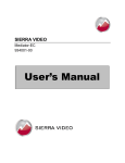
The Crestron E-Server is a small black box with
two RS-232 serial ports. One port is connected to
the routing switcher to control the router. The other
port is for connection to a PC to configure the
Crestron E-Server.
The unit also has an Ethernet port that can be
connected to the user’s network. The user sets the
E-Server to an IP address, and can then use an
Internet browser on a Windows system to address
the E-Server’s software files. The browser will
display web pages that contain simulated router
control panels. By entering numbers or clicking
buttons on these panels, the user can control most
Sierra Video Systems routing switchers.
5
SIERRA VIDEO SYSTEMS
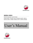
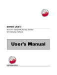
Crestron E-Server
Front Panel
Back Panel
6
SIERRA VIDEO SYSTEMS
2
Chapter
Installation
The Crestron E-Server comes with a Crestron QM-RMC Room Media Controller
Operations Guide. This Operations Guide is for reference only. This Sierra Video
Systems Users Manual is to be used when interfacing with Sierra Video Systems routing
switchers.
System Requirements
Local Area Network must be 100BaseT
Setup PC;
Windows 2000 or newer
P III or better
128 M Ram
Sun Java Web Start
Internet Explorer version 6 or newer
Mounting
Carefully inspect the frame to ensure that there has been no shipping damage. Make
sure all shipping material is removed.
The Crestron E-Server can be mounted anywhere but keep in mind the RS-232
connection should be as short as possible.
Dimensions
The Crestron E-Server is 4 ½” wide, 1 ¼” tall and 5 ½” deep.
7
SIERRA VIDEO SYSTEMS
Connecting to a PC
Connect the Crestron COM B port to the PC comport with an appropriate cable or
cable/dongle combination (supplied by Sierra Video Systems).
This Pin on COM port PC side
(Use female DB-9 connector)
Pin 1 (DCD input)
Pin 2 (RXD input)
Pin 3 (TXD output)
Pin 4 (DTR output)
Pin 5 (GND)
Pin 6 (DSR input)
Pin 7 (RTS output)
Pin 8 (CTS input)
Pin 9 (RI input)
Connects to this pin on Crestron COM B
(Use female DB-9 connector)
No Connection
Pin 3 (TX output)
Pin 2 (RXD input)
No Connection
Pin 5 (GND)
Pin 4 (DTR output)
Pin 8 (CTS input)
Pin 7 (RTS output)
No Connection
Setup
Load the Viewport program from the CD (provided by SVS) onto a PC. Connect the
Crestron E-Server to the PC using the pin connections described above.
Open the Viewport program. Select Setup, Communications Settings.
8
CRESTRON E-SERVER
From the Communications Settings window (Port Settings), select;
Connection Type- RS-232
Port- Your Com port on the PC
Baud Rate- 115200
Parity- None
Data Bits- 8
Stop Bits- 1
Place a check in the XON/XOFF box
Line Pacing for ASCII Uploads- 0
Mode for Network Transfers- XModem
Click OK. Press “enter” on the PC’s keyboard. You should see a prompt in the
Viewport window; QM-RMC>
9
SIERRA VIDEO SYSTEMS
Select Functions, Set Control System IP Information…
From the Ethernet Configuration window, click on Advanced to display the full
window, and then select LAN A and enter your IP information.
Warning:
DO Not change the port Numbers!
Click OK.
10
CRESTRON E-SERVER
From the Viewport Screen select Setup, Communications Settings.
From the Communications Settings window (Port Settings), select;
TCP/IP (Transmission Control Protocol/Internet Protocol) Check Fixed and enter the
IP address you used in the Ethernet Configuration screen.
Connect to a LAN cable.
Click OK. The E-Server should re-connect and give you a prompt. Once it connects,
verify communication by pressing “Enter” on the keyboard. You should get a prompt.
The bottom of the Viewport screen should say;
Port Settings: Connected to “xxx.xxx.xxx.xxx (your IP address)” on Port 41795 (Crestron
Terminal Protocol)
Disconnect the serial cable between the PC and the COM B of the E-Server.
11
SIERRA VIDEO SYSTEMS
3
Chapter
Operation
Introduction
You must have Sun Microsystems Java web start installed on your PC. This can be
downloaded from http://java.com/en/index.jsp . This will enable your PC to correctly read
the web pages stored in the E-Server.
Internet Explorer version 6 or later must be installed, available from:
http://www.microsoft.com/windows/ie/downloads
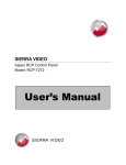
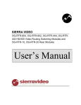
Connect a LAN cable to the E-Server and connect the COM A port to the router’s
HOST port. Verify serial port wiring in the router’s manual.
Warning:
The router’s HOST port MUST be set to 115200 baud.
Routers are typically shipped from the factory at 9600 baud unless specified at the time
of order.
Refer to the router’s manual for processor DIP switch settings and serial cable wiring..
PC
LAN
To Local Area Network
(LAN)
SVS
Router
COM A
E-Server
HOST
Port
13
SIERRA VIDEO SYSTEMS
Once all connections are in place, open your Browser and type in the IP address you
entered in the E-Server setup in the address line.
The following screen should display:
14
CRESTRON E-SERVER
Panel Operation
There are three types of virtual control panels to choose from, depending on your view
preferences. The following section describes each Control Panel type.
Standard Control Panel
Click on Standard Control Panel. The message “Getting Router Model” will display next
to Router Status. This is an indication that the program is attempting to contact the
router for information. This may take several minutes. If this message does not change,
check the connection between the E-Server and the router. This applies to all panel
types.
The Standard Control Panel is intended for switching “all levels” and is not capable of
breaking levels (i.e. Video from Audio).
The Router Configuration section of the screen will display the router’s information.
15
SIERRA VIDEO SYSTEMS
Switching
To make a switch, first select a destination from the Destination drop down list. The
current status of the selected destination will display in the Source window.
Select a new source from the Source drop down list and the “Take” button will light.
Click on “Take” and the switch will take place.
You can also switch by entering the numeric value of the Input or Output.
16
CRESTRON E-SERVER
Status
When a destination is selected, the current status (source currently connected to that
destination) is displayed in the source window.
Lock
You may want to “Lock” a destination to prevent someone on the system from changing
the source of that destination.
To “Lock” a destination, after switching, click on the “Lock” button. The “Lock” button will
change color and the button label will display “Unlock” indicating that the next time the
button is pressed the function will be to “Unlock” the destination. The selected destination
will now be locked preventing source changes to be made to that destination.
To “Unlock” click on the “Unlock” button. The button will change color and the label will
display “Lock”.
17
SIERRA VIDEO SYSTEMS
Breakaway Control Panel
The Breakaway Control Panel gives you the option of switching selected levels or all
levels.
Switching
To make a switch, first select a destination from the Destination drop down list. Select
the levels to be switched (lit level buttons indicate enabled), then select a source from the
Source drop down list and the “Take” button will light.
Click “Take” and the switch will take place.
This panel can also numerically switch and lock destinations similar to the Standard
Control Panel.
Lock
You may want to “Lock” a destination to prevent someone on the system from changing
the source of that destination.
To “Lock” a destination, after switching, click on the “Lock” button. The “Lock” button will
change color and the button label will display “Unlock” indicating that the next time the
button is pressed the function will be to “Unlock” the destination. The selected destination
will now be locked preventing source changes to be made to that destination.
18
CRESTRON E-SERVER
Breakaway Switching
The lit level buttons indicate the levels to be switched (preset).
To turn off a level(s) click on the level button and the button will dim. Click on “All Lvls” to
restore to an “all level” preset.
Status
Individual Level status is indicated in the “Status” window at the top of the screen.
19
SIERRA VIDEO SYSTEMS
Programmable Control Panel
The Programmable Control Panel allows the user to program Source and Destination
buttons to any source or destination desired.
The programming of this panel can be “Password Protected”.
Programming Allowable Inputs and Outputs
Buttons can be programmed to specific sources and destinations allowing access to most
often used sources and destinations.
To program the panel’s defined inputs and outputs;
Click on Pgm Btns
This screen will display;
Enter a Password, if desired.
20
CRESTRON E-SERVER
Select the destinations and sources you want the panel to display from the dropdown
lists.
Panel options
Display and operational options can be selected by placing a check in the appropriate
box.
Source name entry- Placing a check in this box allows the user to select a source
by typing the name of the source in the window next to the source buttons. If this
box is not checked the window will not be displayed.
Show source number- Placing a check in this box displays the virtual source
number in a screen next to the “Take” button.
Destination name entry- Placing a check in this box allows the user to select a
destination by typing the name of the destination in the window next to the
destination buttons. If this box is not checked the window will not be displayed.
Show destination number- Placing a check in this box displays the virtual
destination number in a screen next to the “Lock” button.
21
SIERRA VIDEO SYSTEMS
Programming Buttons
The panel’s buttons may be programmed to provide “shortcuts” for the operator.
With the “Pgm Ctrls” screen open, select a source or destination from the dropdown list
and click on the button to be programmed. The button will display the selection and will
select the programmed I/O when pressed.
Status
Individual Level status is indicated in the “Status” window at the top of the screen.
Warning:
When switching using programmed buttons, the switch will occur as soon as a new source is
selected (auto take).
22
CRESTRON E-SERVER
Lock
You may want to “Lock” a destination to prevent someone on the system from changing
the source of that destination.
To “Lock” a destination, after switching, click on the “Lock” button. The “Lock” button will
change color and the button label will display “Unlock” indicating that the next time the
button is pressed the function will be to “Unlock” the destination. The selected destination
will now be locked preventing source changes to be made to that destination.
23
SIERRA VIDEO SYSTEMS
4
Chapter
Warranty
A. General
Buyer assumes all responsibility for ascertaining the suitability of Sierra Video (hereinafter "SVS")
products for Buyer's intended use. No product sold by SVS is designed or manufactured for use
in any manner or under any conditions other than those described in SVS's instruction manuals
and other printed material for each particular product. If any product is used or applied in a
manner or under conditions not specifically authorized by such written materials or if any product
is used by unqualified or improperly trained personnel, Buyer agrees that SVS shall have no
liability of any kind arising from such use, and Buyer agrees to indemnify and hold SVS harmless
from any claims of third parties arising from such use, and Buyer shall provide SVS with counsel
of SVS's choice to defend against such claims.
B. Limited Warranty
1. This limited warranty applies only to the original purchaser and is non-transferable. This limited
warranty begins on the date of purchase and will be in effect for seven (7) years for new
equipment and for three (3) years for "Factory Refurbished" equipment. Power Supplies and fans
are warranted for three (3) years from the date of purchase for new equipment and two (2) years
for “Factory Refurbished” units, from the date of purchase.
Buyer must obtain a Return Material Authorization ("RMA") number from SVS prior to returning a
product for repair. If, in SVS' sole discretion, the product is found to be defective during the term
of this warranty, SVS will at its option: (a) provide free replacement parts, and/or (b) repair the
unit at an SVS facility. During the warranty period, SVS will make every reasonable effort to
support critical emergencies by supplying no-cost loan equipment while the defective unit is being
repaired. SVS will provide replacement parts and/or factory service at no charge. Buyer bears
the cost of shipping products returned to SVS under this warranty. SVS will bear the cost of
shipping repaired products or replacement parts to the Buyer.
This limited warranty shall not apply to any of SVS's goods which have been altered or which
have been subjected to misuse, mishandling, improper storage or negligence. The
aforementioned provisions do not extend the original warranty period of any goods which have
been replaced by SVS. This limited warranty shall not apply to any goods not of SVS's
manufacture, Buyer to be entitled only to the warranty set forth in the original manufacturer's
limited warranty.
25
SIERRA VIDEO SYSTEMS
THIS LIMITED WARRANTY IS EXPRESSED IN LIEU OF ALL OTHER
WARRANTIES, EXPRESS, IMPLIED OR STATUTORY, INCLUDING WITHOUT
LIMITATION THE IMPLIED WARRANTIES OF MERCHANTABILITY AND OF
FITNESS FOR A PARTICULAR PURPOSE, AND ALL OTHER OBLIGATIONS OR
LIABILITIES ON SVS'S PART.
SVS neither assumes nor authorizes any other person to assume for SVS any other liabilities in
connection with the sale of products of its own manufacture.
2. SVS's liability hereunder on any claim of any kind, except as set forth herein for any loss,
injury to person or property or damage, shall in no case exceed the price allocable to the goods
which give rise to such claim.
3. In no event shall SVS be liable for any damages or injuries to person or property if any
goods do not meet the above limited warranty, including, without limitation, incidental expenses or
consequential or special damages, except as set forth in such limited warranty. The foregoing
states the exclusive remedy of Buyer and the exclusive liability of SVS for any breach of the
foregoing limited warranty.
C. Cancellation
Except as provided in paragraph B immediately above, all sales are final, and Buyer may cancel
this order or return products only upon written consent of SVS.
D. General
In the event of a breach of any of the terms hereof, the non-breaching party shall be entitled to
recover all of its costs, fees, and expenses, including, without limitation, reasonable attorney's
fees, from the breach party incurred as a result of such breach, regardless of whether or not a
suit is actually filed to enforce the terms hereof.
The provision hereof shall be governed by the laws of the State of California (excluding its choice
of law provisions).
The headings are for convenience only and do not limit or amplify the terms and provisions
hereof.
In case any one or more of the provisions set forth herein shall be held to be invalid, illegal, or
unenforceable in any respect, the validity, legality, and enforceability of the remaining provisions
contained herein shall not in any way be affected or impaired thereby.
No waiver, alteration, or modification of any of the provisions hereof shall be binding unless in
writing and signed by an authorized Officer of SVS.
NOTE:
All products returned to SVS for service must have prior approval. Return authorization
requests may be obtained from your SVS dealer.
26