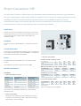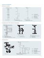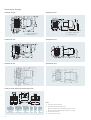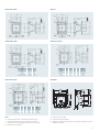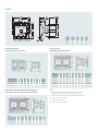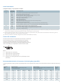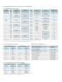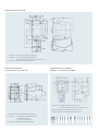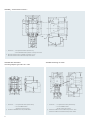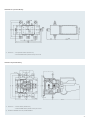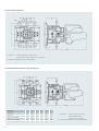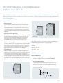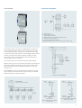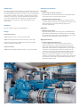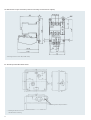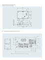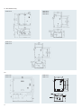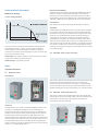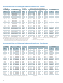
1
SICOP Datasheet 2010 Low Voltage Control Components Answers for industry. s 1 Index Contents 2 Page No. 3TH30 – Contactor Relays 3 3TF – Power Contactors 7 3TF – Contactors for Hoisting Duty 25 3TK5 – AC1 Duty Contactors 29 3UA and 3UC – Bimetal Overload Relays 33 3VU13 and 3VU16 – Motor Protection Circuit Breakers 45 3TW and 3TE – Starters 55 Contactor Relays 3TH30 Reliability and safety are pre-requisites in the choice of the control contactor. Siemens 3TH30 contactor relays satisfy these criteria and thus offer the right choice to the customer. Applications 3TH30 are used in control circuits for switching and signaling purpose. Also they are used for interfacing with the electronic circuits. Standards Contactor relay conforms to IS /IEC 60947-5-1. They also carry CE mark. Range Air break contactor relays are suitable for 10A, (AC15/AC14 rating) at 240V AC and 10A, (DC13 rating) at 24V DC. Benefits and features User friendliness and safety Flexibility • Positively driven contacts • Choice of auxiliary contacts 3TH30 contactor relays comes with 4 contacts as a basic unit (4NO, 3NO+1NC, 2NO+2NC). However the contacts can be extended upto 8 contacts by adding maximum 4 auxiliary contact blocks to this basic unit. This offers flexibly in selection and configuration. • Choice of mounting 3TH30 auxiliary contactors satisfy the conditions for positively driven operation between NO and NC contacts. NO and NC contact do not close at the same time. This is extremely important when they are used in safety circuits of critical applications. This ensures operator safety even during abnormal condition. • SIGUT Termination 3TH30 can be mounted on 35mm DIN rail and they are also suitable for screw mounting. Long Life – Figure touch proof terminals It protects against accidental contact with live parts which ensures operator safety. Superior design of current carrying parts, contact system and the magnet system increases the reliability which also results into higher electrical and mechanical endurance. – Funnel shaped cable entries High reliability – Cable end-stop • Double Break Parallel Bridge contact mechanism This mechanism is available with 3TH30. Such contact mechanism ensures reliable contact at low voltage and low currents (5mA at 17V DC). It also offers unmatched reliability as well as capability to integrate directly into PLC or instrumentation circuits. Reduce wiring time by facilitating quick location of the connecting wire. It decides the insertion depth of the connecting wires. Since the insertion depth is predetermined, insulation of the cable can be cut accordingly and the possibility of insulation getting inadvertently caught under the terminal is avoided. – Captive Screws This feature prevents the screws from falling down thereby facilitates the wiring. Hence, the auxiliary contactors are delivered with untightened terminals. This eliminates the operation of untightening terminals before wiring. – Lug less termination This feature helps in reducing the termination time. Double Break Parallel Bridge Auxilary Contacts 3 Selection and ordering data Contacts in basic unit MLFB - With AC coil MLFB - With DC coil 4NO 3TH30 40-0A.. 3TH30 40-0B.. 3NO+1NC 3TH30 31-0A.. 3TH30 31-0B.. 2NO+2NC 3TH30 22-0A.. 3TH30 22-0B.. Std. pkg. (nos.) 1 .. Please add coil voltage code AC Coil voltages Coil voltage 24 42 110 230 415 Code B0 D0 F0 P0 R0 DC Coil voltages Coil voltage 24 42 48 110 220 250 Code B4 D4 W4 F4 M4 N4 (Other coil voltages are also available.) Technical data Type 3TH30 Standards IS/IEC 60947-5-1 Rated Operational Voltage 690V Rated Impulse withstand voltage 8kV Permissible ambient temp. Storage Service 3TX40.. -50 to +80°C -25 to +55°C Mechanical endurance cycles 30 mill 10 mill Rated operating current Ie/AC12 16A 10A 10A 4A 2A 5.6A 3.6A 1.8A Rated operating current Ie/AC15/AC14 at operating voltage 230V 415V 690V Rated operating current Ie/DC13 at operating voltage Current paths in series 24V 110V 220V 440V Coil Voltage tolerance Current paths in series 1 2 3 1 2 3 10 A 0.9 A 0.45A 0.2 A 10A 2.5A 0.75A 0.5A 10A 10A 2A 0.9A 10 A 0.8 A 0.2 A 0.11A 10A 3.8A 0.85A 0.2A 10A 10A 2A 0.5A 0.8 to 1.1 x Ue Rated coil input AC operated, 50Hz Closing VA/p.f. When closed VA/P.f. W DC operated Closing=when closed Frequency of operation at AC15/DC13 duty cycles/hr 68 / 0.82 10 / 0.29 6.2 3600 Short circuit protection HRC fuse-links Miniature circuit breakers, (C-char.) 16A 16A Degree of protection IP 20 16A 10A For 3TH30 Operating time at 1.0*Us Closing Opening 4 Closing Delay NO AC DC 10-25 ms 30-70ms Opening Delay NC 7-20ms 28-56 ms Opening Delay NO 5-18ms 10-20 ms Closing Delay NC 7-20ms 15-25 ms Accessories and ordering data 2. Add on blocks Auxiliary Contact Block 1. Surge suppressor It is used to reduce the effect of switching overvoltages created during the opening of inductive circuits. Typically they are mounted outside the body of the contactor relay, and are connected in parallel with the coil terminals. Various techniques for the suppression of switching overvoltages can be employed. For example: RC element, Varistor etc 3TX40 10 2A 1NC 3TX40 01 2A 1NO extended 3TX40 10 4A 1NC extended 3TX40 01 4A Coil voltage Varistor MLFB DC 24 - 48 V 24 - 70 V 3TX7 402-3GY1 48 - 127 V 70 - 150 V 3TX7 402-3HY1 127 - 240 V 150 - 250 V 3TX7 402-3JY1 Std. pkg. (nos.) 10 Extended contacts (NO/NC) is early make NO and late break NC combination. Surge Suppressor (Varistor) AC Type Reference 1NO Surge Suppressor (RC Element) Std. pkg. (nos.) Coil voltage RC element DC 24 - 48 V 24 - 70 V 3TX7 402-3RY2 70 - 150 V 3TX7 402-3SY2 48 - 127 V 10 MLFB AC 127 - 240 V 150 - 250 V 3TX7 402-3TY2 240 - 400 V – 3TX7 402-3KY1 240 - 400 V – 3TX7 402-3UY2 400 - 460 V – 3TX7 402-3LY1 400 - 460 V – 3TX7 402-3VY2 Std. pkg. (nos.) 10 Dimensional drawings 3TH30 - 0A c d 3TH30 - 0B Auxiliary Contact Block Identification tag Useful technical information Variety of connections for DC applications 5 6 Power Contactors 3TF For more than 110 years, Siemens has been developing and manufacturing industrial control products. We offer a wide product range which fulfills the demands of our customers regarding performance and reliability. Our aim is to make industrial operation easier ensuring flexible mounting, modular construction and high functionality. With 3TF contactors Siemens has been offering a tried tested trusted solution to control, switch and protect your motors upto 250kW. Applications 3TF power contactors are suitable for switching and controlling squirrel cage and slip-ring motors as well as other AC loads, such as solenoids, capacitors, lighting loads, heating loads and transformer loads. Standards Contactors conform to IS/IEC 60947-4-1. They also carry the CE mark. Coordinated feeder Contactors and bi-relays have been tested for type-2 coordination at Iq = 50kA, 415V AC, 50Hz as per IS/IEC 60947-4-1, for both fuse protected as well as fuseless motor feeders. • Choice of coil voltages Range Air break contactors are available from 9 A to 475A in 3 pole version. AC 50Hz coil code: 3TF30 to 3TF56 Coil voltage (V) 24 42 110 230 415 Code B0 D0 F0 P0 R0 Also available in 2 pole AC version from 45A to 400A. Wide band AC 50 Hz coil code: 3TF30 to 3TF35 Benefits and features Coil voltage (V) Code Flexibility 70-140 150-280 260-460 W110 W220 W415 110-132 220-240 380-460 F7 M7 Q7 AC 50/60 Hz coil code: 3TF57 • Choice of Auxiliary contacts Coil voltage (V) Code Contactor Aux. contacts on basic unit Permissible add-on contact blocks 9A / 12A 1 NO Upto 4NO or 4NC 9A / 12A 1 NC Upto 4NO or 2NC Coil voltage (V) 24 42 48 110 220 250+ 16A/22A - Upto 4NO or 4NC Code B4 D4 W4 F4 M4 N4 32A/38A - Upto 4NO or 4NC + For 3TF3 only 45A to 475A 2NO+2NC 2 x (1NO+1NC) (Other coil voltages are also available.) DC coil code: 3TF30 to 3TF57 The customer can order desired number of contacts thereby reducing the cost. • Choice of mounting Contactor can be mounted on 35mm DIN and they are also suitable for screw mounting (9-38A – DIN / Screw mounting and 45-475A – Screw mounting). 7 High performance • No duration upto 55°C Contactors are suitable for operation in service temperature upto 55°C without derating. This avoids selection of higher rated contactor, thereby reducing cost. • Long Life Superior design of current carrying parts, contact system and the magnet system increases the reliability results into higher electrical and mechanical endurance. • Positively driven contacts 3TF contactors satisfy the conditions for positively driven operation between the main power contacts and the NC contacts. NC contacts positively open before the main contact closes. This is extremely important when power contactors are used in safety circuits of critical applications. • SIGUT Termination • High short-time rating Contactors have a high short-time rating, which makes them suitable for applications having high starting currents and long run-up times. High reliability • High insulation voltage and impulse withstand voltage capacity ensures reliable performance during occasional abnormal increase in supply voltage. • Double break parallel bridge contact mechanism This mechanism is available for auxiliary contacts. Such contact mechanism ensures reliable contact at low voltage and low currents (5mA at 17VDC). It also offers unmatched reliability. (Chances of 2 mal-operations in 100 mill. operations as against 4460 for single bridge contacts) – Figure touch proof terminals* It protects against accidental contact with live parts which ensures operator safety. – Funnel shaped cable entries Reduce wiring time by facilitating quick location of the connecting wire. – Cable end-stop It decides the insertion depth of the connecting wires. Since the insertion depth is predetermined, insulation of the cable can be cut accordingly and the possibility of insulation getting inadvertently caught under the terminal, is avoided. – Captive Screws This feature prevents the screws from falling down thereby facilitates the wiring. Hence, the contactors are delivered with untightened terminals. This eliminates the operation of untightening terminals before wiring. Double Break Parallel Bridge Auxilary Contacts – Lug less termination This feature helps in reducing the termination time. User friendliness and safety • Arc Chamber Interlock (45A and above) It prevents the contactor from switching ON, if the arc chamber is not fitted properly. Thus avoids accidents to plant and personnel. * Finger touch proof terminals are available upto 85 A 8 Selection and ordering data Contactor size Rated current (A) Ie AC3 at 415V, 50Hz, 3ph Motor kW at 415V 50Hz, 3ph 0 9 4 1NO $ 1NC $ 3TF30 10-0A.. 3TF30 01-0A.. 3TF30 10-0B.. 3TF30 01-0B.. 12 5.5 1NO $ 1NC $ 3TF31 10-0A.. 3TF31 01-0A.. 3TF31 10-0B.. 3TF31 01-0B.. 16 7.5 –$ 3TF32 00-0A.. 3TF32 00-0B.. 22 11 –$ 3TF33 00-0A.. 3TF33 00-0B.. 32 15 –$ 3TF34 00-0A.. 3TF34 00-0B.. 38 18.5 –$ 1 2 3 4 6 8 10 12 Auxiliary contacts AC 50 Hz coil Type Pl. fill in coil voltage code DC coil Type Pl. fill in coil voltage code 3TF35 00-0A.. 3TF35 00-0B.. 2NC $ 3TF46 02-0A..ZA01@ 3TF46 02-0D..ZA01@ 3TF47 02-0A..ZA01@ 3TF47 02-0D..ZA01@ 45 22 2NO + 63 30 2NO + 2NC $ 70 37 2NO + 2NC $ 3TF47 72-0A.. 3TF47 72-0D.. 75 42 2NO + 2NC $ 3TF48 22-0A..ZA01@ 3TF48 22-0D..ZA01@ 85 45 2NO + 2NC $ 3TF49 22-0A..ZA01@ 3TF49 22-0D..ZA01@ 110 55 2NO + 2NC $ 3TF50 02-0A.. 3TF50 02-0D.. 140 75 2NO + 2NC $ 3TF51 02-0A.. 3TF51 02-0D.. 2NC $ 170 90 2NO + 3TF52 02-0A.. 3TF52 02-0D.. 205 110 2NO + 2NC $ 3TF53 02-0A.. 3TF53 02-0D.. 250 132 2NO + 2NC $ 3TF54 02-0A.. 3TF54 02-0D..1) 300 160 2NO + 2NC $ 3TF55 02-0A.. 3TF55 02-0D..1) 400 200 2NO + 2NC $ 3TF56 02-0A.. 3TF56 02-0D..1) 250 2NC $ 3TF57 02-0C.. 3TF57 02-0D..1) 475 2NO + 1) Please connect DC coil circuit as recommended on page 16 $ For more auxiliary contacts please refer table below - “auxiliary contact blocks” @ For box type (SIGUT) terminal, order 2 nos. 3TX7 460-0E Coil voltage code AC 50Hz: 3TF30 to 3TF56 Std. pkg. (nos.) 1 Auxiliary contact blocks Coil voltage 24 42 110 230 415 For Contactor Description Type Std. pkg. (nos.) Code B0 D0 F0 P0 R0 3TF30 to 35 1NO 1NC 1NO ext 1NC ext 3TX4 010-2A 3TX4 001-2A 3TX4 010-4A 3TX4 001-4A 10 Second 1NO+1NC Left Second 1NO+1NC Right 3TY7 561-1K 3TY7 561-1L 1 Coil voltage code AC 50/60 Hz: 3TF57 3TF46 to 57 Coil voltage (V) 110-132 220-240 380-460 F7 M7 Q7 Code 2 Pole AC contactors - 3TF Coil voltage code DC: 3TF30 to 3TF57 For single phase and 2 phase applications with AC coils + Coil voltage (V) 24 42 48 110 220 250 Code B4 D4 W4 F4 M4 N4 + For 3TF3 only 2) Coil voltage code AC 50Hz: 3TF (2 Pole AC Contactor) Coil voltage Code 110 230 415 F0 P0 R0 (Other coil voltages are also available) Contactor Size Rated current Ie (A) AC3, 415V Type2) 3 45 3TF46 02-0A..ZB01 3 63 3TF47 02-0A..ZB01 3 70 3TF47 72-0A..ZB01 6 110 3TF50 02-0A..ZB01 6 140 3TF51 02-0A..ZB01 8 170 3TF52 02-0A..ZB01 8 205 3TF53 02-0A..ZB01 10 250 3TF54 02-0A..ZB01 10 300 3TF55 02-0A..ZB01 12 400 3TF56 02-0A..ZB01 Std. pkg. (nos.) 1 9 Technical data Contactor Size Permissible ambient temperature Storage Service 0 Type 3TF30 °C °C -55 to +80 -25 to +55 Maximum operating voltage V 690 Rated insulation voltage Ui (At Pollution Degree 3)1) V 690 Rated impulse strength Uimp kV 8 Cycles Cycles 15 x 106 15 x 106 Mechanical endurance (make/break operations) AC DC 1 3TF31 3TF32 2 3TF33 3TF34 3TF35 10 x 106 10 x 106 Rating of contactors for AC loads AC-1 duty, switching resistive load Rated operational current Ie Ratings of three-phase loads p.f.=1 at 55°C AC-2 and AC-3 duty Rated operational current Ie2) Nominal rating of slipring or squirrel-cage motors at 50/60 Hz. AC-4 duty (contact endurance approx. 2x10⁵ make-break operations at Ia=6Ie) Rated operational current Ie Rating of squirrel-cage motors at 50/60Hz. Max. permitted rated operational current Ie/AC-4 = Ie/AC-3 upto 500V. Ref. life curve for the life. Used as stator contactor (upto 690V) (AC-2 duty) Stator currents Ies On-load factor (ED)3) with intermittent duty * Applicable up to 500V Used as rotor contactor (upto 690V) (AC-2 duty) Rotor current Ier On-load factor (ED)3) with intermittent duty Locked rotor voltage Uer AC-6b duty, switching low-inductance individual three-phase capacitors at 50/60Hz4) (we also offer special capacitor duty contactors) Thermal loading Power loss per current path at Ie/AC-3 at 40°C upto 690V at 55°C upto 690V A A 21 20 32 30 65 55 at 415V 500V 690V kW kW kW 13 17 22 19.7 26 34. 36 47.5 62.7 upto 415V 500V 690V at 415V 500V 690V A A A kW kW kW 9 9 6.6 4 5.5 5.5 12 12 8.8 5.5 7.5 7.5 16 16 12.2 7.5 10 11 22 17 12.2 11 11 11 upto 690V at 415V 500V A kW kW 3.3 1.54 1.7 4.3 2.1 2.5 7.7 3.5 4.6 690V kW 2.54 3.45 6 20% 40% 60% 80% A A A A 20 20 20 20 20% 40% 60% 80% Starting Plugging / Control A A A A V V 31 31 31 31 1320 660 415V 500V 690V 20 20 20 20 32 32 27 15 21 23 38 38 27. 18.5 25 23. 8.5 4 5.2 15.6 8.2 9.8 18.5 9.8 11.8 6.6 13 15.5 25(46*) 25(37*) 25(33*) 25(30*) 85 67 60 55 73 58 52 47 1320 660 125 106 95 87 1320 660 kVAR kVAR kVAR 4 4 4 7.5 7.5 7.5 10 s current A W 90 0.6 1 2 3 1 2 3 1 2 3 at 24V 110V 220V 440V A A A A 20 2.1 0.8 0.6 20 12 1.6 0.8 20 20 20 1.3 30 4.5 1 0.4 30 30 5 1 30 30 30 2.9 55 6 1 0.4 55 55 6 1.1 55 55 45 2.9 1 2 1 2 at 24V 110V 220V 440V A A A A 20 0.15 - 96 1.1 16.7 16.7 16.7 130 1 176 1.6 400 2 400 2.5 Rating of contactors for DC loads DC-1 duty, switching resistive load (L/R < 1mS) Rated operational current Ie (at 55°C) Number of current paths in series connection DC-3 and DC-5 duty, shunt & series motors (L/R < 15mS) Rated operational current Ie (at 55°C) Number of current paths in series connection 1) As per IS/IEC 60947-1 2) Ratings at 1000V AC - upon enquiry. 10 1 2 20 0.35 - 3 20 20 1.75 0.2 20 30 0.75 7 0.2 1 0.09 0.27 3 30 30 3.5 0.6 20 55 0.75 7 0.2 1 0.1 0.27 ontime x 100 cycle time Max. switching freq. z = 50 per hour. Ratings at higher frequency upon enquiry. 3) On-load factor (ED) in % = 3 55 55 3.5 0.6 3 3TF46 4 3TF47 3TF47 7 6 3TF48 3TF49 3TF50 8 3TF51 3TF52 10 3TF53 3TF54 12 3TF55 3TF56 3TF57 -55 to +80 -25 to +55 1000 1000 1000 1000 8 8 10 x 106 3 x 10⁶ 10 x 106 3 x 10⁶ 90 80 100 90 100 90 120 100 120 100 170 160 230 210 240 220 325 300 325 300 425 400 600 550 52 67 91 52 67 91 52 67 91 66 86 114 66 86 114 105 138 183 132 173 228 138 181 240 195 260 340 195 260 340 262 345 457 381 476 657 45 45 45 22 30 40 63 63 63 30 41.4 57.2 70 70 70 37 46 60.1 75 75 75 42 50.7 70 85 85 75 45 59 70 110 110 110 55 76.3 105 140 140 110 75 98 105 170 170 170 90 118 163 205 205 170 110 145 163 250 250 250 132 178 245 300 300 250 160 210 245 400 400 400 200 284 392 475 475 400 250 329 392 24 13.1 15.8 28 15.3 18.4 31 16.9 20.4 34 18.6 22.4 42 23 27 54 29.5 35.5 68 38 46 75 42 50 96 54 65 110 63 76 125 72 86 150 88 107 150 88 107 21.8 25.4 28.2 30.9 38 49 63 69 90 105 119 147 147 123 98 87 80 138 110 98 90 138 110 98 90 154 122 109 100 246 195 174 160 323 256 229 210 339 268 240 220 462 367 327 300 617 490 436 400 800 670 600 550 150 150 138 126 1500 750 219 174 155 142 1500 750 219 174 155 142 1500 750 243 193 172 158 2000 1000 389 309 275 253 2000 1000 510 405 361 332 2000 1000 535 425 378 348 2000 1000 729 579 516 474 2000 1000 972 772 688 632 2000 1000 1336 1061 946 869 2000 1000 60 80 60 100 130 100 150 190 150 200 265 200 30 35 30 50 62.5 50 360 3.5 1 80 6 1.2 0.48 1 5 0.75 0.2 0.1 500 6 500 6 800 7.5 800 10 2 3 1 2 80 80 7 1.2 80 80 80 3 100 12 2.5 0.8 100 100 13 2.4 2 80 12.5 1.1 0.27 3 80 80 3.5 0.6 1 6 1.25 0.35 0.15 2 3 100 100 100 6 3 100 100 100 100 1.75 4 0.42 0.8 880 10 1140 14 1 2 3 160 18 3.4 0.8 160 160 20 3.2 160 160 160 11.5 1 2 160 160 2.5 160 0.6 2.5 0.17 0.65 3 160 160 160 1.4 1360 14 1 1640 20 2 200 200 18 200 3.4 20 0.8 3.2 1 2 2500 16 3 1 200 200 200 11.5 300 33 3.8 0.9 3 200 200 200 2.5 200 200 0.6 2.5 200 0.17 0.65 1.4 1 2500 23 2 3 300 300 300 4 300 300 300 11 2 3 300 300 300 3 300 300 0.6 2.5 300 0.18 0.65 1.4 3400 40 1 400 33 3.8 0.9 1 4200 40 2 3 400 400 400 4 400 400 400 11 2 3 400 400 400 3 400 400 0.6 2.5 400 0.18 0.65 1.4 4) Ratings for capacitor - banks in parallel - upon enquiry. Minimum inductance of 6μH required between parallel connected capacitors. 11 Power Contactors Technical Data Contactor Size Type Switching frequency z (Contactors without overload relay) No load AC DC at AC-1 at AC-2 at AC-3 at AC-4 Coil ratings (cold coil 1.0 x Us) Operation Cycles/hr Cycles/hr Cycles/hr Cycles/hr Cycles/hr Cycles/hr 0 3TF30 10,000 1,500 2,000 1,000 1,000 250 1 2 3TF31 3TF32 3TF33 10,000 1,500 2,000 1,000 1,000 250 5000 1,500 1,500 750 750 250 5000 1,500 1,500 750 750 250 3TF34 5000 1,500 1,200 750 750 250 Supply frequency Hz 50 50 Closing p.f. Closed p.f. VA 68 0.79 10 0.29 68 0.82 10 0.29 101 0.83 12.1 0.28 6.2 6.2 6.2 6.2 11.7 11.7 AC operation 50Hz DC operation Closing Closed Coil voltage tolerance VA W W Operation AC/DC at 24V DC 0.8 to 1.1 x Us 0.8 to 1.2 x Us 3 3TF35 3TF46 3TF47 3TF47 7 5000 1,500 1,200 600 600 200 5000 1,000 1,000 600 12005) 400 5000 1,000 1,000 400 1000 300 5000 1,000 1,000 400 1000 300 50 50 183 0.6 17 0.29 400 2.1 0.8 to 1.1 x Us Operating times at 1 x Us 8) AC operation Closing Opening ms ms 10-25 4-18 10 - 25 5 - 20 13 - 32 5 - 10 17 - 30 5 - 25 DC operation Closing Opening ms ms 30-70 12-20 40 - 80 10 - 20 58 -107 13 - 17 22 - 40 105 - 115 Auxiliary contacts Rated thermal current Ith = rated operational current Ie / AC-12 A 10 10 Rated operational current Ie / AC-15/AC-14 at rated operational voltage Ue upto 125V 220V 415V 500V A A A A 10 10 5.5 4 10 6 3.6 2.5 upto 48V 110V 220V 440V A A A A 10 2.1 0.8 0.6 10 3.2 0.9 0.33 upto 24V 48V 110V 220V 440V A A A A A 10 5 0.9 0.45 0.25 10 5 1.14 0.48 0.13 Rated operational current Ie / DC12 at rated operational voltage Ue Rated operational current Ie / DC13 at rated operational voltage Ue Conductor cross-sections Main conductor Solid Finely stranded with end sleeve Pin end connector Solid or stranded Tightening torque Finely stranded with cable lug Terminal bar (max. width) Solid or stranded Tightening torque mm2 mm2 mm2 AWG Nm mm2 mm AWG Nm 2 x (0.5 to 1, 1 to 2.5), 1x4 2 x (0.75 to 2.5) 1 x (1 to 2.5) 2 x (18 to 12) 0.8 to 1.4 mm2 mm2 mm2 AWG Nm 2 x (0.5 to 1, 1 to 2.5), 1 x 4 2 x (0.75 to 2.5) 1 x (1 to 2.5) 2 x (18 to 12) 0.8 to 1.4 2 x (2.5 to 6) 2 x (1.5 to 4) 1 x (1 to 6) 2 x (14 to 10) 1 to 1.5 1 to 16 1 x (5 to 16, 2.5 to 10) 2 x (1 to 6) 2 x (14 to 6) 2.5 to 3.0 2 x (6 to 16) 1 x (10 to 35), 2 x (10 to 25) – 2 x (10 to 1/10) 4 to 6 10 to 35 12 7 to 1/0 4 to 6 Auxiliary conductor Solid Finely stranded with end sleeve Pin end connector Solid or stranded Tightening torque 2 x (0.5 to 1, 1 to 2.5), 1 2 x (0.75 to 2.5) 1 x (1 to 2.5) 2 x (18 to 12) 0.8 to 1.4 Short-circuit protection Main circuit (Fuse type 3NA3) Co-ordination Type - 1 Type - 2 Auxiliary circuits 5) With AC coil. With DC coil: 1000 oprs/hr. 6) Including switching contactor. 12 A A 35 25 35 25 63 32 63 32 80 80 A A 16 6, if overload relay auxiliary contacts are in the contactor coil circuit 7) Rated value of the control voltage. 80 80 160 125 160 125 160 160 4 6 8 10 12 3TF48 3TF49 3TF50 3TF51 3TF52 3TF53 3TF54 3TF55 3TF56 3TF57 5000 1,000 900 400 1000 300 5000 1,000 900 350 850 300 5000 1000 800 400 1000 300 5000 1000 800 300 750 200 5000 1000 800 300 700 200 5000 1000 750 250 500 130 3000 1000 800 300 700 200 3000 1000 750 250 500 130 3000 1000 700 200 500 150 2000 1000 500 170 420 150 50 50/60 Lower7) 50 50 330 0.5 32 0.23 550 0.45 39 0.24 420 2.7 500 2.7 50 50 910 0.38 58 0.26 1430 0.34 84 0.24 8766) 116) 2450 0.21 115 0.33 12166) 13.36) 1136 1 16 0.34 13066) 146) 11106) 246) Upper7) 1900 1 45 0.16 0.8 to 1.1 x Us 22 - 35 5 - 30 22 - 37 8 - 30 25 - 50 10 - 30 25 - 40 10 - 30 25 - 40 8 - 30 48 - 70 80 - 100 32 - 40 95 -105 28 - 32 185 - 195 32 - 45 10 - 20 36 - 45 10 - 20 40 - 55 10 - 20 44 - 60 12 - 15 10 10 10 10 6 3.6 2.5 10 6 3.6 2.5 10 6 3.6 2.5 10 3.2 0.9 0.33 10 3.2 0.9 0.33 10 3.2 0.9 0.33 10 5 1.14 0.48 0.13 10 5 1.14 0.48 0.13 10 5 1.14 0.48 0.13 16 to 70 15 3 to 2/0 6 to 8 35 to 95 20 35 to 95 20 50 to 240 25 50 to 240 25 50 to 240 25 50 to 240 25 50 to 240 30 10 to 14 10 to 14 14 to 24 14 to 24 14 to 24 14 to 24 14 to 24 2 x (0.5 to 1, 1 to 2.5), 1 x 4 2 x (0.75 to 2.5) 1 x (1 to 2.5) 2 x (18 to 12) 0.8 to 1.4 250 160 250 160 2 x (0.5 to 1, 1 to 2.5) 2 x (0.75 to 2.5) 1 x (1 to 2.5) 2 x (18 to 12) 0.8 to 1.4 400 200 400 250 400 250 400 250 2 x (0.5 to 1, 1 to 2.5) 2 x (0.75 to 2.5) 1 x (1 to 2.5) 2 x (18 to 12) 0.8 to 1.4 500 400 500 400 800 500 800 500 8) The opening time delay increases when the contactor coil is protected against voltage peaks. (e.g. Varistor: +2 to +5ms) 13 Electrical Life Curves 3TF30 to 3TF49 contactors 3TF50 to 3TF57 contactors 14 Typical Circuit Diagrams Direct On Line starter a) Main circuit b) Control circuit for momentary-contact control S0 S1 S = = = K1 F1 F2 F3 = = = = ‘OFF’ Push button ‘ON’ Push button Maintained command switch Main contactor Main circuit fuse Overload relay Control circuit fuse c) Control circuit for maintained-contact control Forward / Reverse starter (Electrical Interlocking) Main circuit S0 S1 S2 S : : : : 'OFF' Push button 'ON Clockwise' Push button 'ON Anti-clockwise' Push button Selector Switch 'Clockwise - OFF - Anti-clockwise' Push button control (momentary command) K1 : Clockwise contactor K2 : Anti-clockwise contactor Selector switch control (command needs to be maintained) F1 : Main circuit fuses F2 : Overload relay F3 : Control circuit fuse Star Delta starter Main circuit Control circuit for push button control (momentary command) S0 S1 K1 K2 K3 K4 F2 F1 F3 = = = = = = = = = ‘OFF’ Push button ‘ON’ Push button Line contactor Star contactor Delta contactor Star delta timer (7PU60 20) Overload relay Backup fuse Control circuit fuse 15 Auto Transformer starter b) Auxiliary circuit for momentary-contact control S0 S1 K1 K2 K3 K5 = = = = = = K4 F1 F2 F3 = = = = a) Main Circuit Please refer page no. 70 for selection of switchgear for autotransformer starting method Internal connection diagram for DC coil circuits K1 : Sizes 3 to 6, 3TF46 to 3TF51 K1 : Sizes 8 to 12 3TF52 to 3TF56 K2 : 3TF30 10 OB.. for 3TF52-55 3TF32 00-OB.. for 3TF56 The control circuits indicated by dotted lines are to be wired by customer. 16 K1 : Size 12 3TF57 K2 : 3TC44 17 4A.. ‘OFF’ Push button ‘ON’ Push button Star contactor Transformer contactor Main contactor Contactor relay (2NO + 2NC) Time relay (7PU6020) Main circuit fuses Overload relay Control circuit fuse Terminal Designation Size 0, 3TF30/31 AC and DC Coil Size 3 to 12, 3TF46 to 3TF57 AC Coil Size 2, 3TF32/33/34/35 AC and DC Coil Size 3 to 12, 3TF46 to 3TF56 DC Coil Add-on contact block for 3TF30/31/32/33 Size 12, 3TF57 DC Coil Permissible Mounting Position 3TF30 to 3TF33 - AC operation 3TF30 to 3TF33 - DC operation 3TF34 to 3TF57 - AC operation 3TF46 to 3TF57 - DC operation 3TF34/35 - DC operation 17 Accessories and ordering data Surge suppressor (Varistor) for 3TF46-56 1. Mechanical interlocking kit Mechanical interlock is required when the supply from two different sources is available. Also the same is required for the application involving reversing of motor. Here two contactors are mechanically interlocked with the help of mechanical interlock kit. This ensures closing of only one contactor at a time. Thus prevents a short circuit upon load changeover from one contactor to another. For Contactor AC3 Rating MLFB Std. pkg. (nos.) Contactor 9 to 38A 3TF30 to 35 3TX4 091-1A # 10 45/63/70A 3TF46/47/47-7 3TX7 466-1YA0 2 75/85A 3TF48/49 3TX7 486-1YA0 2 110/140A 3TF50/51 3TX7 506-1YA0 2 170/205A 3TF52/53 3TX7 526-1YA0 2 250/300A 3TF54/55 3TX7 546-1YA0 2 400 A 3TF56 3TX7 566-1YA0 2 110/170 A 3TF50/52 3TX7 526-1YA09 1 170/250 A 3TF52/54 3TX7 546-1YA09 1 #: W/O base plate (not required) 2. Surge suppressor It is used to reduce the effect of switching overvoltages created during the opening of inductive circuits. Typically they are mounted outside the body of the contactor, and are connected in parallel with the coil terminals. Various techniques for the suppression of switching overvoltages can be employed. For example: RC element, Varistor etc. Coil Voltage Std. pkg. (nos.) Type AC DC Less than 48V 24 - 70V 3TX7 462-3GY1 48 - 127V 70 - 150V 3TX7 462-3HY1 127 - 240V 150 - 250V 3TX7 462-3JY1 240 - 400V – 3TX7 462-3KY1 400 - 600V – 3TX7 462-3LY1 10 Surge suppressor (RC Element) for 3TF30-3TF35 Coil Voltage AC Std. pkg. (nos.) Type DC 24 - 48V 24 - 70V 3TX7 402-3RY2 48 - 127V 70 - 150V 3TX7 402-3SY2 127 - 240V 150 - 250 V 3TX7 402-3TY2 240 - 400V – 3TX7 402-3UY2 400 - 460V – 3TX7 402-3VY2 10 3. Connector The 3TS90 connector is used to mount the motor protection circuit breaker 3VU on the contactor 3TF with screw terminals. It enables mechanical and electrical connection between contactor and motor protection circuit breaker. RC Element: RC element The effective increase in the capacitance of the coil circuit reduces the amplitude and rate of rise of switch off overvoltage spikes to such an extend that no rapid restriking occur. Varistor: Varistor limit the maximum value of the overvoltage because they become highly conductive above a threshold value. Until this threshold value is reached shower discharge occurs for small duration. Varistor MPCB Size of Current connector MLFB Rating Selection table: Surge suppressor (Varistor) for 3TF30-3TF35 Coil Voltage 18 Range: Type AC DC 24 - 48 V 24 - 70V 3TX7 402-3GY1 48 - 127V 70 - 150V 3TX7 402-3HY1 127 - 240V 150 - 250V 3TX7 402-3JY1 240 - 400V – 3TX7 402-3KY1 400 - 600V – 3TX7 402-3LY1 Std. pkg. (nos.) Contactor MLFB 0.16 to 3TF30 / 31 20A AC3 Current Rating MLFB of Connector Std. pkg. (nos.) I 3VU13 9 / 12 A 3TS90 01-8K 1 II 3VU13 6 to 25A 3TF32 / 33 16 / 22A 3TS90 02-8K 1 Benefits: 10 Direct mounting of 3VU MPCB on 3TF contactor eliminates the need of power wiring and ensures secure connection. In addition, the assembly time and size of the feeder is reduced which results in cost saving. The overall assembly also looks contemporary. Spares and ordering data 1. Auxiliary Contact Blocks Add – on Contact Blocks: In-built contact configuration For Contactor 3TF30-35 Add on contact blocks Type Std. pkg. (nos.) 1NO 1NC 1NO ext 1NC ext 3TX40 10-2A 3TX40 01-2A 3TX40 10-4A 3TX40 01-4A 10 1NO+1NC Left 1NO+1NC Right 1NO + 1NC (Extd) Right 3TY7 561-1A 3TY7 561-1B 3TY7 561-1E 1 Second 1NO+1NC Left Second 1NO+1NC Right 3TY7 561-1K 3TY7 561-1L 1 3TF46/47/477 Special block for DC Coil Circuit 3TY7 461-1F 1 3TF48 to 57 3TY7 481-1F 1 3TF46-57 3TF46-57 Special block for DC Coil Circuit 2. Main contact kits / arc chambers / AC-DC coils For contactor type (AC3 rating) 1) Main contact kits (6 fixed & 3 moving contacts) Arc chambers AC coils1) DC coils1) 3TF30 (9A) – – 3TF31 (12A) – – 3TF32 (16A) 3TY7 420-0A – 3TY7 403-0A.. 3TY4 803-0B.. 3TF33 (22A) 3TY7 430-0A – 3TF34 (32A) 3TY7 340-0C 3TY7 342-0C 3TF35 (38A) 3TY7 350-0C 3TY7 352-0C 3TY7 443-0A.. 3TY7 443-0B.. 3TF46 (45A) 3TY7 460-0YA 3TY7 462-0YA 3TF47 (63A) 3TY7 470-0YA 3TY7 472-0YA 3TF477 (70A) 3TY7 477-0YA 3TY7 477-0YD 3TY7 463-0A.. 3TY7 463-0D.. 3TF48 (75A) 3TY7 480-0A 3TY7 482-0A 3TY7 483-0A.. 3TY7 483-0D.. 3TF49 (85A) 3TY7 490-0A 3TY7 492-0A 3TF50 (110A) 3TY7 500-0YA 3TY7 502-0YA 3TF51 (140A) 3TY7 510-0YA 3TY7 512-0YA 3TY7 503-0A.. 3TY7 503-0D.. 3TF52 (170A) 3TY7 520-0YA 3TY7 522-0YA 3TF53 (205A) 3TY7 530-0YA 3TY7 532-0YA 3TY7 523-0A.. 3TY7 523-0D.. 3TF54 (250A) 3TY7 540-0YA 3TY7 542-0YA 3TF55 (300A) 3TY7 550-0YA 3TY7 552-0YA 3TY7 543-0A.. 3TY7 543-0D.. 3TF56 (400A) 3TY7 560-0YA 3TY7 562-0YA 3TY7 563-0A.. 3TY7 563-0D.. 3TF57 (475A) 3TY7 570-0YA 3TY7 572-0YA 3TY7 573-0C 3TY7 573-0D.. Std. pkg. (nos.) 1 Please fill in coil voltage code from table below Coil voltage code AC 50Hz: 3TF30 to 3TF56 Coil voltage code DC: 3TF30 to 3TF57 Coil voltage 24 42 110 230 415 Code B0 D0 F0 P0 R0 + Code 24 42 48 110 220 250+ Code B4 D4 W4 F4 M4 N4 For 3TF3 only (Other coil voltages are also available) Coil voltage code AC 50/60 Hz: 3TF57 Coil voltage (V) Coil voltage (V) 110-132 220-240 380-460 F7 M7 Q7 19 Dimensional drawing 3TF30/31 AC Coil 3TF30/31 DC Coil Auxiliary contact block Identification tag 3TF32/33 AC Coil 3TF32/33 DC Coil 3TF34/35 AC Coil 3TF34/35 DC Coil Auxiliary contact block Identification tag 3TF30 to 3TF32, with mechanical interlock kit Notes 1) Dimensions for coil terminals Type a (AC coil) a (DC coil) b1 b2 c 3TF30/31 116 148 90 100 78 3TF32/33 127 159 91 101 85 2) Dimensions for mounting terminals Minimum clearance from insulated components = 5mm Minimum clearance from earthed components = 10mm 3) size of power terminals 4) Size of auxiliary terminals 20 3TF46 and 3TF47 3TF47 7 3TF48 and 3TF49 3TF50 and 3TF51 Type a1 c Type a1 a2 b c φd 3TF48 8 107 3TF50 15 37 149 134 6.6(M6) 3TF49 10.5 116 3TF51 20 42 159 139 9(M8) 3TF54/55 3TF52 and 3TF53 Type a1 a2 b c φd 3TF52 20 42 174 154 6.6(M6) 3TF53 25 48 184 159 9(M8) Notes 4) Dimension for mounting. 1) Minimum clearance from insulated components = 3mm Minimum clearance from earthed components = 10mm 5) Dimension for power terminal. 2) Dimension with second auxiliary contact block on both sides 6) 3TF53 The conductor bars protrude over the contactor edges on top and bottom by 2mm each. 3) Dimension for coil terminal. 21 3TF56/57 Type 3TF46/47/477/48/49 with Mechanical Interlock Kit a1 a2 b1 b c 3TF56 25 200 178 48 3TF57 30 209.5 182 52 b2 c1 c2 d1 e g1 a1 a2 b1 b2 c1 c2 d1 e g1 3TF50/51 300 240 210 185 160 18 147 260 9 (M8) 3TF52/53 330 270 240 215 203 18 162 315 9 (M8) 3TF46/47/477 240 180 165 145 141 18 117 150 7 (M6) 3TF54/55 350 290 265 240 219 21 172 375 11 (M10) 3TF48/49 260 200 175 155 158 18 127 160 7 (M6) 3TF56/57 380 310 265 240 243 21 187 385 11 (M10) 3TF50 and 3TF52 with Mechanical Interlock Kit 3TF52 and 3TF54 with Mechanical Interlock Kit Notes 1) Minimum clearance from insulated components = 3mm Minimum clearance from earthed components = 10mm 2) Dimension with second auxiliary contact block on both sides 3) Dimension for coil terminal. 4) Dimension for mounting. 5) Dimension for power terminal. Type 22 d 3TF50 to 3TF57 with Mechanical Interlock Kit For Contactor For Contactor a a1 a2 b1 b2 c1 c2 d1 g1 3TF52 & 50 330 270 240 215 203 18 154.5 11 3TF54 & 52 350 290 265 240 219 21 167 11 Useful information Categories of duty - as per IEC 947 / IS 13947 Current Utilisation Categories Typical Application AC AC1 AC2 AC3 AC4 AC5a AC5b AC6a AC6b AC7a AC7b AC8a AC8b Non-inductive or slightly inductive loads, resistance furnances Slipring motors; starting, switching off Squirrel-cage motors; starting, switching off motors during running(1) Squirrel-cage motors; starting, plugging, inching Switching of electric discharge lamp controls Switching of incandescent lamps Switching of transformers Switching of capacitor banks Slightly inductive loads in household appliances and similar applications Motorloads for household applications Hermetic refrigerant compressor motor(2) control with manual resetting of overload releases Hermetic refrigerant compressor motor(2) control with automatic resetting of overload releases DC DC1 DC3 DC5 DC6 Non-inductive or slightly inductive loads, resistance furnaces Shunt-motors: starting, plugging, inching, dynamic braking of d.c motors Series-motors: starting, plugging, inching, dynamic braking of d.c motors Switching of incandescent lamps (1) AC3 category may be used for occasional inching (jogging) or plugging for limited time periods such as machine set-up; during such limited time periods the number of such operations should not exceed five per minute or more than ten in a 10-min period. (2) Hermetic refrigent compressor motor is a combination consisting of a compressor and a motor, both of which are enclosed in the same housing, with no external shaft or shaft seals, the motor operating in the refrigent (3) Selection of contactors for utilisation categories from AC-5a to AC-8b and DC6 upon enquiry. Contact life calculation: Contactors have bounce free operation. Electrical life is influenced by the breaking currents. For normal AC3 duty the breaking current is the rated operational current and for AC4 duty, the typical breaking current is 6 times the rated operational current. In case of mixed duty, the expected life is determined as under Where X = expected life for mixed duty A = expected life for normal AC3 duty B = expected life for 100% AC4 duty C = proportion of inching operations as a percentage of total operations. Recommended selection of contactors for hoisting duty (upto 85A) In hoisting operation, slipring motors are generally used. For this typical hoisting duty, we recommend the contactors listed in the following table. Contactor Type Stator Protection Maximum load current with hoisting motor. For intermittent duty S3 25% Rotor Protection Maximum load current with hoisting motor(Delta circuit). For intermittent duty S3 40% 60% 100% 25% 40% 60% Max rotor standstill voltage 100% A A A A A A A A V 3TF31 10 10 9 8 15 14 13 12 660 3TF33 17 16 15 13 25 24 22 20 660 3TF45 28 25 23 20 42 38 35 30 660 3TF47 49 45 40 30 73 68 60 45 750 3TF49 68 62 54 45 100 95 80 68 1000 23 Recommended substitutes for discontinued 3TA/3UA19 For standard application (AC3 duty) AC3 rating 415V, 50Hz Discontinued contactor Size Discontinued bi-relay 3TA67 3TA76 7.8A 1 3TA21 3UA1911 16A 22A 3TA11 30A 3TA22 32A 2 3UA1928 3TF32 3TF33 3TF34 2 63A 70A 3TF46-Z 3TA24 4 105A 3 3TA16 3UA1938 110A 140A 170A 8 200A 3TA28 3UA66 250A 300A 12 3TB56 3UA66 – – – 400A 475A 3TF47-Z 4 6 3TA28-Y 3.8 3UA5000 3UA5200 10 12 7.5 11 15 3UA5500 # 18.5 20 3UA5800-Z1 22 30 3TF47-7 3UA5800-Z2 37 3TF48/49 3UA5800-Z1 45 3TF50 3UA5830 55 3TF51 8 4 5.5 3TF35 45A 1) Motor kW 415V, 50Hz, 3ph. Bi-relay 3TF31 1 3TA13 38A Contactor 3TF30 0 9A 12A Size 75 3TF52 95 3TF53 110 3TF54 3UA6230 3TF55 3TF56 3TF57 132 160 220 3UA6830 250 # use 3UA50 + 3UX1418 to replace 3UA19 28 (upto 12A) use 3UA52 + 3UX1420 to replace 3UA19 28 (upto 25A) 1) For crane/hoisting/inching application, replace 3TA24 with 3TF48/49 contactors For inching application (AC4 duty) Adaptor plate for replacing 3TA Discontinued contactor New contactor Size Type 3TA Size Type 3TF 1 3TA21 1 3TF32 1 3TA11 1 3TF33 2 3TA22 2 2 3TA13 4 Type 3TA61-0A by 3TH80/82-0A 3TX6 406-0A 3TA67/21 by 3TH80/82 3TA67/21 by 3TF30/31 & 3TA21/11 by 3TF32/33 3TX21 43 1YA0 3TF34 3TA22/13 by 3TF32/33/44/45 3TX22 42 1YA0 2 3TF35 3TA24 by 3TF46/47/477 3TX24 46 1YA0 3TA24 4 3TF48 3TA24/16 by 3TF48/49 3TX16 48 1YA0 4 3TA16 6 3TF50 3TA16 by 3TF50/51 3TX16 50 1YA0 8 3TA28 8 3TF52 3TA28 by 3TF50/51 3TX28 50 1YA0 3TF56 3TA28 to 3TF52/53 3TX28 52 1YA0 12 3TB56 12 For crane application (AC2 duty, S3 100% inching) Discontinued contactor New contactor Size Type 3TA Size Type 3TF 1 3TA21/11 1 3TF33 2 3TA22/13 2 3TF35 4 3TA24 4 3TF49 8 3TA28 8 3TF5200* 12 3TB56 12 3TF5600* * Hoisting duty contactors, designed specially for hoisting duty. 24 Adaptor plates, to replace Contactors for Hoisting Duty AC slipring motors are most commonly used for the hoisting applications. AC2 duty pertains to starting and switching off the slipring motors. In case of hoisting duty breaking current is the starting current and frequency of switching is high. The table shows the making and breaking capacity at normal and at hoisting application where Ie indicates the rated full load current. Making Breaking During Normal operation at full load 2.5 * Ie Ie Hoisting application at full load 2.5 * Ie 2.5 * Ie less than 2.5 * Ie Less than Ie During Normal operation at partial load Application AC-2 operation is the typical duty for starting and switching off fully-loaded slipring motors in the starting phase. The rating of the contactor, to switch the motors, is selected primarily on the basis of rated make & break capacity and desired electrical endurance. Standard The contactors comply with the “Regulations to low voltage switchgear” of DIN VDE 0660 and IS/IEC 60947-4-1. Range Hoisting duty contactors are available from 110A to 400A (AC2/AC3 rating). Benefits and features Operator safety • Arc Chamber Interlock It prevents the contactor from switching ON, if the arc chamber is not fitted properly. Thus avoids accidents to plant and personnel. • Finger touch proof terminals It protects against accidental contact with live parts which ensures operator safety. High performance • No duration upto 55°C Contactors are suitable for operation in service temperature upto 55°C without derating. This avoids selection of higher rated contactor, thereby reducing cost. Long life • “Hoisting Duty “Contactors are provided with new design of contacts (AgSnO2 instead of AgCdO) resulting in high electrical and mechanical life. • They are electrically superior in taking care of excessive stresses coming on contactors during their operations in crane applications. Reliability • The “Hoisting Duty” Contactors have vacuum impregnated coils which are suitable for high frequency switching and high vibrations. This helps in reducing coil failures. • Side mounted auxiliary contact blocks are screw mounted and not snap fitted to withstand vibrations and high frequency operation. Selection and ordering data Hoisting duty contactors – For high switching frequency / inching applications with AC coils, 2NO+2NC aux. contacts Contactor size Rated current Ie (A) AC2/AC3 at 415V Type 6 110 3TF50 00-0A.. 8 170 3TF52 00-0A.. 10 250 3TF54 00-0A.. 12 400 3TF56 00-0A.. Std. pkg. (nos.) 1 Coil voltages: Coil voltage - 50Hz Code 110V 230V 415V F0 P0 R0 (Other coil voltages are also available) 25 Technical Information A. Recommended selection of contactors for hoisting duty In hoisting operation, slipring motors are generally used. For this typical hoisting duty, we recommend the contactors listed in the following table. Contactor Type Stator Protection Maximum load current with hoisting motor. For intermittent duty S3 Rotor Protection Maximum load current with hoisting motor(Delta circuit). For intermittent duty S3 Max rotor standstill voltage 25% 40% 60% 100% 25% 40% 60% 100% 3TF50 00 0A 100 88 78 65 150 130 115 95 3TF52 00 0A 145 130 115 95 220 195 170 150 1000 3TF54 00 0A 225 200 180 160 340 300 270 240 1000 3TF56 00 0A 355 325 290 250 530 490 435 375 1000 1000 When 3 conducting paths are connected in parallel, the maximum load current rises to 2.5 times the value given in this table. When 2 conducting paths are connected in parallel, it rises to 1.8 times the value given in this table. B. Selection of contactors for contact endurance: with normal and inching operation C. Selection of contactors for contact endurance: with mixed operation Contactors suffer more erosion during inching operation than when stopping motors from a steady speed, i.e. normal operation. With slipring motors the starting current can be up to 2.5 times the rated current of the motor which means that this current has to be broken when inching is taking place. During normal operation, on the other hand, only the rated current has to be broken under full-load; under part-load it is even less. Determining contact endurance from AC-2 duty (Ic = 2.5 x Ie) will only give correct results when 100% inching operation is involved. When mixed operation is involved, i.e. primarily breaking of the motor rated current but with some breaking of higher currents due to inching, the endurance of the contacts can be calculated approximately from the following equation: Max. permissible current and attainable contact endurance when braking starting current given below PF ≥ 0.4 (2.5 x Ie) Contact life when breaking the stator contactor load currents for S3-100% duty, Ic = Ie, no inching A A Operating cycles Approx. Contactor Type Where X = Contact endurance with mixed operation cycles. A = Contact endurance with normal operation (Ia = Ie) in operating cycles, from Fig. 1. B = Contact endurance with inching operation (Ia = Multiple of Ie) in operating cycles, from Fig. 2, Breaking current Ia/AC-2 = 2.5xIe. Approx. Operating cycles 275 425 625 280,000 250,000 250,000 65 95 160 3,500,000 3,100,000 2,700,000 3TF5000 3TF5200 3TF5400 1000 150,000 250 2,500,000 3TF5600 C = Proportion of inching in total operating Cycles in %. The maximum permitted current (e.g. locked-rotor current of motor) must not exceed the values given in the “Max. starting current and attainable contact endurance” column. The values cannot be increased by paralleling pole assemblies. Fig. 1 Contact endurance of 3TF contactors as a function of breaking current when switching resistive and inductive AC loads. 26 Example 1 Motor rated current 150A. Selected contactor: 3TF5600 Contact endurance in operating cycles at 400V With inching of 0% 10% 20% 50% 100% 5.4 x 10⁶ 4.6 x 10⁶ 3.9 x 10⁶ 2.3 x 10⁶ 1.4 x 10⁶ Example 2 Maximum permitted motor rated current for a contact endurance of 2,000,000 operating cycles at 400V. Fig. 2 Contact endurance for mixed operation as a function of motor rated current. Motor on rated load, inching at 2.5 times motor rated current (slipring motor). The contact endurance as a function of the motor rated current with mixed operation can be determined from Fig. 2 for proportions of inching of 0, 10, 20, 50 and 100%. The values obtained are only applicable if rated motor load is used continuously. In practice therefore, the contact endurance should be greater. Stator contactor Permitted rated current of slipring motor with inching Type 10% approx. A 20% approx. A 50% approx. A 100% approx. A 3TF50 00 75 68 48 33 3TF52 00 110 95 66 48 3TF54 00 175 160 125 80 3TF56 00 240 230 160 120 D. NOMOGREM Apart from knowing the figure for contact endurance in operating cycles, users are also interested to know what period of time this amounts to before the contacts have to be changed. The value can be ascertained from the nomogram in Fig. 3. using the Nomogram Fig. 3 Nomogram for determining contact endurance in year (250 working days) and months with daily operating hours of 4, 8, 12, 16, 20 and 24 h. 27 Draw a line from the point on the left-hand scale indicating the required number of operating cycles to the point on the right hand scale indicating the required number of operating cycles per hour. Then, from the point where this line intersects with the centre axis, draw a horizontal line to the left or right scale for the actual number of daily operating hours. Note: If a figure of 365 days per annum is being employed instead of 250, the total operating time obtained from the nomogram must be multiplied by 0.68. Dimensional drawing The “Hoisting Duty” Contactors are mechanically similar to our existing 3TF power contactors. Therefore they have exactly same dimensions as the corresponding 3TF power contactors. Please refer page nos. 21 and 22. Useful technical information Starting method of Slip ring motor (AC2 duty): Example: Service requirements: 1.4 million operating cycles endurance, 200 operating cycles per hour, 16 hours service per day. Three types of the contactors are used to control the three phase slip-ring motors: the stator contactor, the acceleration contactor and the rotor short circuit contactor. Result: Stator contactor Initially the stator contactor (K1) is closed to energize the motor. None of the rotor contactor (K2 or K3) is closed yet. Hence all the resistances are present in the rotor circuit. The starting current can reach to 1.5 to 4 times of the rated operational current. The AC2 rating of the stator contactor is selected as per the load factor of the motor. Total operating time approx =18 months. Accessories and ordering data: AC Coils: 1) Spare coils for Type1) 3TF50 00 0A.. 3TY7 503-0A ..0-0H 3TF52 00 0A.. 3TY7 523-0A ..0-0H 3TF54 00 0A.. 3TY7 543-0A ..0-0H 3TF56 00 0A.. 3TY7 563-0A ..0-0H Std. pkg. (nos.) 1 Code 110 230 415 F0 P0 R0 (Other coil voltages are also available) Spares and ordering data Contact kits: 28 Spare contact kit for Type 3TF50 00 0A.. 3TY7 500-0ZA 3TF52 00 0A.. 3TY7 520-0ZA 3TF54 00 0A.. 3TY7 540-0ZA 3TF56 00 0A.. 3TY7 560-0ZA on time *100 Cycle time (on time + rest time) Acceleration contactor Now acceleration contactor (K2) is closed which short circuits the resistances (R1). The sizing of this contactor (K2) is as per AC1 rated operational current. The current flow time per cycle and the number of cycles per hour has to be considered for the selection. Coil voltage code AC 50Hz: Coil voltage Load factor = Std. pkg. (nos.) 1 Rotor short circuit contactor At the end, the rotor short circuit contactor (K3) closes, short circuiting the last resistance bank (R2) thus remove all the resistances from the rotor circuit. The starting period is hence completed. The duty of this contactors is characterized by the small closing stress. the decisive factor is the thermal stress. The duty factor is considered while finding out the permissible values of the rated operational rotor current for rotor contactors. Picture below shows the acceleration (K2) and the rotor short circuiting contactor (K3) in the delta connection. If they are connected in star then the ratings are reduced by 35%. AC1 Duty Contactors 3TK5 When contactors are not required to make or break current but only carry the current, the contactors can be used to its full AC1 rating. Siemens 3TK5 AC1 duty contactors can be offered in such cases. Application 3TK5 AC1 duty contactors are widely used in sugar mills, DC drives and changeover applications. Also they can be offered for the applications like switching resistive loads, battery charging etc where the AC1 rating of the contactor is suitable. Standards 3TK5 contactors conform to IS/IEC 60947-4-1. They also carry the CE mark. Range 3TK5 AC1 duty air break contactors are available from 190A (AC1) to 500A (AC1) in 3 pole version. Benefits and features High performance • No duration upto 55°C SICOP contactors are suitable for operation in service temperature upto 55°C without derating. This avoids selection of higher rated contactor, thereby reducing cost. • Long Life Superior design of current carrying parts, contact system and the magnet system increases the reliability results into higher electrical and mechanical endurance. • Positively driven contacts 3TF contactors satisfy the conditions for positively driven operation between the main power contacts and the NC contacts. NC contacts positively open before the main contact closes. This is extremely important when power contactors are used in safety circuits of critical applications. Selection and ordering data Contactor size Rated current Ie (A) AC1 at 415V 6 190 3TK50 02-0A.. 8 315 3TK52 02-0A.. 10 380 3TK54 02-0A.. 12 500 3TK56 02-0A.. High reliability • High insulation voltage and impulse withstand voltage capacity ensures reliable performance during occasional abnormal increase in supply voltage. 1) Std. pkg. (nos.) 1 Coil voltage code AC 50Hz: Coil voltage User friendliness and safety Type1) Code 110 230 415 F0 P0 R0 • Arc Chamber Interlock It prevents the contactor from switching ON, if the arc chamber is not fitted properly. Thus avoids accidents to plant and personnel 29 Technical data Contactor Type 3TK50 Mechanical Endurance (make/break operations) Oprns 10 million Electrical Endurance in acc. with ACI duty at Ie (make/break operations) Oprns 0.5 million Rated insulation voltage Ui Permissible ambient temperature storage service Rated impulse withstand voltage Uimp V 1000 °C °C -55 to +80 -25 to +55 KV 8 3TK52 3TK54 3TK56 Rating of contactors for AC loads AC-1 duty, switching resistive load Raed operational current le Rating of three-phase loads p.f = 1 at 55 deg C 40 deg C upto 690V 55 deg C upto 690V A A 200 190 340 315 400 380 530 500 kW kW kW 125 164 217 207 272 360 250 329 434 329 433 571 A 85 105 138 170 415V 500V 690V kW kW kW 45 59 78 55 72 96 75 98 130 90 118 156 10 s current A W 990 13 1450 19 1725 30 2300 38 No load AC at AC1 at AC3 1/hr 1/hr 1/hr 5000 650 1000 5000 650 1000 3000 650 1000 3000 650 1000 closing VA p.f VA P.f 550 0.45 39 0.24 910 0.38 58 0.26 1430 0.34 84 0.24 2450 0.21 115 0.33 415V 500V 690V AC-2 and AC-3 duty Rated operational current le Maximum rating of slipring or squirrel cage motors at 50/60Hz Thermal loading Power loss per current path at le/AC3 Switching frequency z (contactors without overload relay) Coil ratings AC operation 50Hz upto 690V closed Coil voltage tolerances Operating times at 1.0 X Us AC operation 0.8 to 1.1 x Us closing time opening time ms ms 22 to 37 8 to 30 25 to 40 10 to 30 25 to 40 10 to 30 25 to 40 8 to 20 Co-ordination Type 1 Type2 A A 315 250 355 350 500 500 800 500 Short circuit protection of contactors Main circuit 30 Accessories and ordering data: Spares and ordering data Auxiliary contact blocks: Contact kits: For Contactor 3TK5 Description Type Second 1NO+1NC Left 3TY7 561-1K Second 1NO+1NC Right 3TY7 561-1L Std. pkg. (nos.) Spare contact kit for Type 3TK50 02-0A.. 3TY7 500-0KA 1 3TK52 02-0A.. 3TY7 520-0KA 3TK54 02-0A.. 3TY7 540-0KA 3TK56 02-0A.. 3TY7 560-0KA Coils: For Contactor Type * 3TK50 3TY7 503-0A.. 3TK52 3TY7 523-0A.. 3TK54 3TY7 543-0A.. 3TK56 3TY7 563-0A.. Std. pkg. (nos.) 1 *Please fill in coil codes from table below Std.pkg. (nos.) 1 Dimensional drawing The “3TK5 AC1 duty” Contactors are mechanically similar to our existing 3TF5 power contactors. Therefore they have exactly same dimensions as the corresponding 3TF power contactors. 3TK50, 3TK52, 3TK54 and 3TK56 are having exactly same dimensions as those of 3TF50, 3TF52, 3TF54 and 3TF56 respectively. Please refer page nos. 21 and 22. Coil voltage code AC 50Hz: Coil voltage Code 110 230 415 F0 P0 R0 31 32 Bimetal Overload Relays 3UA and 3UC The 3UA / 3UC thermal overload relays are suitable for customers from all industries, who want guaranteed optimum inverse time delayed protection of their electrical loads. The relays meet the requirements of IS/IEC 60947-4-1. Application 1 3UA overload relay: 3UA5/6 are 3 pole adjustable bi-metal overload relays mainly suitable for normal starting applications. They provide accurate and reliable protection to motors against overload as per CLASS 10A. They also offer protection against single phasing and unbalanced voltages. 3UC overload relay: 3UC5/6 are 3 pole adjustable, saturable CT operated bi-metal overload relays mainly suitable for heavy starting applications (i.e. when heavy masses are to be put in motion resulting in larger starting period). They provide accurate and reliable protection to motors against overload as per CLASS 30. They also offer protection against single phasing and unbalanced voltages. If single-phase AC or DC loads are to be protected by the 3UA / 3UC thermal overload relays, all three bimetal strips must be heated. For this purpose, all main current paths of the relay must be connected in series. Standards Bimetal relays conform to IS/IEC 60947-4-1. They also carry the CE mark. Range 3UA5: 0.1 to 120A, (Class 10A, without CT) 3UA6: 85 to 630A, (Class 10A, CT operated) 3UC5/6: 2.4 to 400A (Class 30, CT operated) Relay overview Overload relay operates on the bi-metallic principle. The heater winding wound on the bimetal strips carry the current flowing through the motor. In case of overload, the current carried through the heater winding is more than the rated current. This heats up the bimetals. Due to this bi-metal strips bend and open the NC contact of the relay, which is connected in the control circuit of the contactor, thus disconnects the motor from the supply. The tripping time is inversely proportional to the current flowing through the bi-metal strips. Bi-relays are therefore, referred to as “current dependent” and inverse-time delayed relays. 2 3 5 4 1. Connection for mounting onto contactors: Optimally adapted in electrical, mechanical and design terms to the contactors, these connecting pins can be used for direct mounting of the overload relays. Stand-alone installation is possible as an alternative (in some cases in conjunction with a stand-alone installation module). 2. Selector switch for manual/automatic RESET (blue): With this switch you can choose between manual and automatic RESET. A device set to manual RESET can be reset locally by pressing the RESET button. A remote RESET is possible using the RESET modules (accessories), which are independent of size. 3. TEST button (red): Trip circuit can be manually checked by using this button. During this simulation the NC contact (95-96) is opened and the NO contact (97-98) is closed. This tests whether the auxiliary circuit has been correctly connected to the overload relay. The relay must be reset with the RESET button if it has been set to manual RESET. If the thermal overload relay has been set to automatic RESET, then the overload relay is automatically reset when the TEST button is released. 4. Motor current setting dial: Setting the device to the rated motor current is easy with the large rotary knob. (Recessed dial, hence no possibility of accidently change in current setting.) 5. Trip indicator (Green): A separate mechanical Green Trip Indicator is provided on the front cover of the relay to indicate the tripped state of the ‘manual reset’ relay. 33 Recovery time After tripping due to overload, the thermal overload relays require some time until the bimetal strips have cooled down. The device can only be reset after the bimetal strips have cooled down. This time (recovery time) depends on the tripping characteristics and strength of the tripping current. The recovery time allows the load to cool down after tripping due to overload. Benefits and features High performance • In-built single phasing protection for -25 to 55° C. For this purpose the relays are temperature compensated between service temperatures of -25° C to +55° C. User friendliness and safety • SIGUT termination Technique – Shrouded auxiliary terminals Increases safety, as they protect against accidental contact with live parts. – Funnel shaped cable entries Reduce wiring time by facilitating quick location of the connecting wire. – Cable end-stop They decide the insertion depth of the connective wire. As the wire cannot now protrude into the relay housing, it does not hamper the movement of the auxiliary contacts. Since the insertion depth is predetermined, insulation of the cable can be cut accordingly and the possibility of insulation getting inadvertently caught under the terminal, is avoided. – Captive Screws This feature prevents the screws from falling down thereby facilitates the wiring. Hence, the relays are delivered with untightened terminals. This eliminates the operation of untightening terminals before wiring. – Lug less termination This feature helps in reducing the termination time. In case of phase loss the current through the other two windings increases by 1.732 times the rated current of the motor. The current now flows only through the 2 bimetallic strips which should produce the required force on the tripping mechanism. This needs higher currents for longer time. As current is not too high so the relay might take higher time to trip. This can cause damage to the motor. Similar condition happens in case of phase unbalance. To take care of these conditions our birelays are constructed such that they offer a built-in single phasing protection using differential slider principle. • Temperature compensation The temperature compensation feature reduces the effect of the ambient temperature on the tripping behavior. This ensures the minimum tripping current lies within the specified range 34 – Screw-driver guides reduce wiring time as they allow the use of power screw-drivers. Flexibility • Potential free Auxiliary Contacts Potential free 1NO + 1NC contact arrangement is provided as a standard feature. The 1NC contact is used in the control circuit of the contactor for disconnecting the motor in case of overload, whereas the 1NO contact can be used for various applications such as indication. • Mounting 3UA5: suitable for direct mounting or independent mounting (with the help of independent mounting accessory) 3UA6 and 3UC5/6: suitable for Independent mounting. Selection and ordering data: Setting range Type reference (A) Backup HRC fuse 3NA A (max) Mounting Std. pkg. (nos.) Setting range Type reference (A) Normal Motor Starting time Backup HRC fuse 3NA A (max) Mounting Std. pkg. (nos.) 3UA58 30 3UA50 0.1 0.16 0.25 - 0.16 0.25 0.4 3UA50 00-0A 3UA50 00-0C 3UA50 00-0E 2 2 2 0.4 0.63 0.8 - 0.63 1 1.25 3UA50 00-0G 3UA50 00-0J 3UA50 00-0K 2 2 4 1 1.25 1.6 2 - 1.60 2 2.5 3.2 3UA50 00-1A 3UA50 00-1B 3UA50 00-1C 3UA50 00-1D 6 6 6 10 2.5 3.2 4 - 4 5 6.3 3UA50 00-1E 3UA50 00-1F 3UA50 00-1G 10 16 16 5 6.3 8 10 - 8 10 12.5 14.5 3UA50 00-1H 3UA50 00-1J 3UA50 00-1K 3UA50 00-2S 20 25 25 25 1 1.25 1.6 - 1.6 2 2.5 3UA52 00-1A 3UA52 00-1B 3UA52 00-1C 6 6 6 2 2.5 3.2 - 3.2 4 5 3UA52 00-1D 3UA52 00-1E 3UA52 00-1F 10 10 16 4 5 6.3 - 6.3 8 10 3UA52 00-1G 3UA52 00-1H 3UA52 00-1J 16 20 25 8 10 12.5 16 - 12.5 16 20 25 3UA52 00-1K 3UA52 00-2A 3UA52 00-2B 3UA52 00-2C 25 32 50 50 10 12.5 16 - 16 20 25 3UA55 00-2A 3UA55 00-2B 3UA55 00-2C 32 50 50 20 25 32 36 - 32 36 40 45 3UA55 00-2D 3UA55 00-2Q 3UA55 00-2R 3UA55 00-8M 80 80 80 80 16 20 25 32 40 50 57 63 70 - 25 32 40 50 57 63 70 80 95 3UA58 00-2CZ1 3UA58 00-2DZ1 3UA58 00-2EZ1 3UA58 00-2FZ1 3UA58 00-2TZ1 3UA58 00-2PZ1 3UA58 00-2VZ1 3UA58 00-2UZ1 3UA58 00-8YZ1 50 63 80 100 100 125 125 160 160 16 20 25 32 40 50 57 63 - 25 32 40 50 57 63 70 80 3UA58 00-2CZ2 3UA58 00-2DZ2 3UA58 00-2EZ2 3UA58 00-2FZ2 3UA58 00-2TZ2 3UA58 00-2PZ2 3UA58 00-2VZ2 3UA58 00-2UZ2 50 63 80 100 100 125 125 160 70 85 95 - 95 - 105 - 120 3UA58 30-5B 3UA58 30-5C 3UA58 30-5D 160 160 200 With Contactor 3TF50 1 135 180 250 320 400 3UA62 30-5A 3UA62 30-5B 3UA62 30-5C 3UA62 30-5D 3UA62 30-5E 224 250 400 400 500 Independent 1 - 500 - 630 3UA68 30-5F 3UA68 30-5G 500 630 Independent 1 3UA62 30 With Contactor 3TF30/31 1 85 115 160 200 250 - 3UA68 30 320 400 Long Motor Starting time (Heavy duty) 3UC50 30 2.5 4 6.3 8 3UA52 - 4 6.3 10 12.5 3UC50 30-5E 3UC50 30-5G 3UC50 30-5J 3UC50 30-5K 16 25 25 32 Independent 1 16 25 40 63 3UC58 30-5A 3UC58 30-5C 3UC58 30-5E 3UC58 30-5G 32 63 100 125 Independent 1 - 100 - 160 3UC62 30-5J 3UC62 30-5A 250 315 Independent 1 3UC66 30-5B 3UC66 30-5C 3UC66 30-5E 500 630 630 Independent 1 3UC58 30 10 16 25 40 With Contactor 3TF32/33 - 3UC62 30 1 63 100 3UC66 30 125 160 250 - 200 - 250 - 400 3UA55 With Contactor 3TF34/35 1 3UA58 With Contactor 3TF46 3TF47 3TF48 3TF49 1 With Contactor 3TF47 7 35 Technical Data Type 3UA50 3UA52 3UA55 3UA58 Trip class 3UA5830 3UA6230 3UA6830 3UC5030 3UC5830 10A 3UC6230 3UC6630 30 Phase failure protection 9 9 9 9 9 9 9 9 9 9 9 Changeover to auto-reset at site 9 9 9 9 9 9 9 9 9 9 9 RESET button (trip-free) Blue 9 9 9 9 9 9 9 9 9 9 9 Ambient temperature compensation 9 9 9 9 9 9 9 9 9 9 9 Trip indicator Green 9 9 9 9 9 9 9 9 9 9 9 TEST button Red 9 9 9 9 9 9 9 9 9 9 9 Terminal for contactor coil 9 9 9 X X X X X X X X Permissible service temperature 25°C to +55°C Mounting Contactor/ Contactor/ Contactor/ Contactor/ Contactor/ 3TF30/31 3TF32/33 3TF34/35 3TF46 to 3TF50 49 Independent Main Circuit Rated current (Max) A 14.5 25 45 95 120 400 630 12.5 63 160 400 Rated insulation voltage Ui (Pollution degree 3) V 690 690 690 1000 1000 1000 1000 1000 1000 1000 1000 Rated impulse withstand Uimp kV 6 6 6 8 8 8 8 8 8 8 8 Direct Direct Direct Direct Direct Indirect Indirect Indirect Indirect Indirect Indirect 35 to 70 50 to 120/ 240* 2 x 240 1 to 4 – – – – – 1 to 2.5 35 120 240 2 x 240 – – – – Heating Conductor cross-section Solid or stranded sqmm 2.5 to 6 2.5 to 6 1.5 to 25 2.5 to 35 Finely stranded with end sleeve sqmm 1.5 to 4 1.5 to 4 1 to 16 1.5 to 25 Multi-conductors with cable lugs sqmm – – – – – 50 to 120/ 240* Flats sqmm – – – – – 1 x 20 x 3 2 x 30 x 5 – 1 x 15 x 3 1 x 20 x 5 2 x 30 x 5 2 x 3- x 5* M4 M4 M5 M5 M8 M10 M10 M4 M6 M8 M10 Terminal screw – Power loss per pole (max) Minimum setting W(VA) 0.9 0.9 1.2 2.6 2.8 5 6(9) 2.5 2.5 3.5 5.5 Maximum setting W(VA) 2.25 2.25 3 4 4 7 15(22) 6.5 6.5 9 14 Auxiliary Circuit (application for all types) Auxiliary contacts 1NO + 1NC (Potential free) Rated thermal current Ith A 6 Short circuit protection (max) A 6 (HRC Fuse type 3NA7) Switching AC15 V 24 capacity A 2 V 24 A 1 DC13 60 125 1.15 60 110 220 0.4 0.22 0.1 Conductor cross-section Solid or stranded sqmm 2 x (1 to 2.5) Finely started with end sleeve sqmm 2 x (0.75 to 1.5) Terminal screw * For relay above 180 A 36 M3.5 230 415 500 1.5 1.25 1 1 Characteristic Curves Tripping characteristics The current/time curves show the relationship between the tripping time from cold state and multiples of the set current Ie. When the relay is at operating temperature and carrying 100 % Ie, the tripping times are reduced to approximately 25 %. Tripping curve is applicable to 3-pole loads and 2-pole loads. For singlepole loads, the tripping curves lie between curves of 3-pole loads and 2-pole loads. For normal operation, all 3 bimetallic strips of the overload relay must be heated. The overload relays 3UA / C are suitable for protecting motors with phase control. For protecting single-phase or DC-loads, therefore, all three main conducting paths must be connected in series. Tripping curve for 3 pole loads is then applicable. The release current with a 3-pole symmetrical load is between 105 % and 120 % of the set current. The above curves are the general characteristics curves; for individual characteristics curves of each rating, please contact our nearest sales office. 37 Accessories and ordering data 1. Adaptor: To convert contactor mounting relay to independent mounting, (Fig. 1) suitable for screw type mounting and 35 mm DIN rail mounting. 2. Protective cover*: To avoid tampering of the setting, auto manual mode or test button. (Fig. 2) 3. Reset cord*: To reset the relay in switchboard with door closed. (Length: 600 mm) (Fig. 3) 4. Reset plunger with funnel*: Instead of reset cord for resetting the relay in switchboard with door closed. (Fig. 4) Fig. 3: Reset cord with holder Fig. 1: Adaptor Fig. 4: Reset plunger + Funnel Fig. 1: Relay with adaptor for independent mounting Description Type reference Relay type Reset Plunger 3UX1 011 3UA5/6, 3UC5/6 Funnel 3UX1 013 Reset cord with Holder (600mm) 3UX1 016 3UA5/6, 3UC5/6 Protection Cover 3UX1 111 - 1YA 3UX1 110 - 1YA 3UA5/6 3UA58/5830 10 Adaptor to convert to independent mounting 3UX1 418 3UX1 420 3UX1 425 3UX1 421 3UX1 421 - 0XA 3UA50 3UA52 3UA55 3UA58 3UA5830 1 Set of terminals to convert relay type 3UX58 11 3UA5800-2 or to 3UA5800-2 Z2 to 3UA5800-2 Z1 3UX58 12 3UA5800-2 Z1 or 3UA5800-2 Z2 to 3UA5800-2 3UX58 13 * Only one accessory at the time Fig. 2: Protective cover 38 3UA5800-2 or 3UA5800-2 Z1 to 3UA5800-2 Z2 Std. pkg. (nos.) 10 5 10 Dimensional Drawing 3UA50 with independent Mounting Adapter Type 3UX1 418 ** Dimension for the square OFF-button (stroke 3mm) Dimension for the round RESET-button (stroke 2.5mm) less 2.5mm 1) For 35mm standard (DIN) mounting rail 3UA50 mounted on 3TF30/31 Auxiliary Contact a b c d 1NO or 1NC 125 85 108 55 1NO + 1NC or 2NO + 2NC 130 100 100 60 2) Minimum clearance from earthed element 10mm 39 3UA52/55 with independent mounting Type ** Dimension – For square OFF button (Stroke 3mm) – For Round RESET button (Stroke 2.5mm) less 2.5 mm 1) Suitable for DIN RAIL 35mm as per DIN EN 50022 3UA52 mounted on 3TF 32/33 * Minimum clearance from the earthed components ** Dimension – For square OFF button (Stroke 3mm) – For Round RESET button (Stroke 2.5mm) less 2.5mm 40 Dim a b 3UA52 + 3UX1420 M4 14.3 3UA55 + 3UX1425 M5 18.2 3UA55 mounted on 3TF 34/35 * Minimum clearance from the earthed components ** Dimension – For square OFF button (Stroke 3mm) 1) Suitable for DIN RAIL 35mm as per DIN 50022 – For round RESET button (Stroke 2.5mm) less 2.5mm 3UA58 with independent mounting adaptor type 3UX1 421 3UA5800 mounted on 3TF46/47 3UA5800_.. Z1 mounted on 3TF48/49 * Dimension – For square OFF button (Stroke 3mm) – For round RESET button (Stroke = 2.5mm) less 2.5mm 1) Minimum clearance from insulated components : 3mm Minimum clearance from earthed components: 10mm * Minimum clearance from the earthed components ** Dimension – For square OFF button (Stroke 3mm) – For round RESET button (Stroke 2.5mm) less 2.5mm 1) Suitable for DIN RAIL 35mm as per DIN 50022 g φ g1 φ g2 3UA58+ a1 a2 a3 b1 b2 b3 c1 d1 d2 d3 e1 e2 f1 f2 f3 3TF46/47 90 113 70 117 175 100 123 8 25 25 94 34 80 63 122 28 4.8 6.1 3TF48/49 100 123 80 133 194 110 140 10.5 25 26.5 116 31.5 89 71 132 39 5.5 6.1 41 3UA5800_.. Z2 mounted on 3TF47 7 * Dimension – For square OFF button (Stroke 3mm) – For round RESET button (Stroke = 2.5mm) less 2.5mm 1) Minimum clearance from insulated components : 3mm Minimum clearance from earthed components: 10mm 3UA5830 with individual mounting adaptor type 3UX1 421 - OXA * Dimension – For square OFF button (Stroke 3mm) – For round RESET button (Stroke 2.5mm) less 2.5mm 1) Suitable for DIN RAIL 35mm as per DIN 50022 3UA5830 mounting on 3TF50 * Dimension – For square OFF button (Stroke 3mm) – For round RESET button (Stroke 2.5mm) less 2.5mm 1) Minimum clearance from insulated components : 3mm Minimum clearance from earthed components: 10mm 42 3UA6230 CT Operated Birelay ** Dimension – For square OFF button (Stroke 3mm) – For round RESET button (Stroke 2.5mm) less 2.5mm 3UA68 CT Operated Birelay ** Dimension – For TEST button (Stroke 3mm) – For Round RESET button (Stroke 2.5mm) less 2.5mm 2) Suitable for DIN RAIL 75mm as per DIN EN 50023 43 3UC50 CT Operated Birelay ** Dimension – For Square OFF button (Stroke 3mm) – For Round RESET button (Stroke 2.5mm) less 2.5mm 2) Suitable for DIN RAIL 75mm as per DIN EN 50023 3UC5830/3UC6230/3UC6630 CT Operated Birelay 44 Relay Type A B C D E F 3UC58 30 46 135 69 6.6 150 15x3 3UC62 30 46 140 69 9 160 20x3 3UC66 30-5B (200A) 50 146 69 9 160 20x3 3UC66 30-5C-5E(400A) 50 146 70 11 171 25x4 ** Dimension – For TEST button (Stroke 3mm) – For Round RESET button (Stroke 2.5mm) less 2.5mm 2) Suitable for DIN RAIL 75mm as per DIN EN 50023 Motor Protection Circuit Breakers 3VU13 and 3VU16 3VU13/3VU16 is suitable for use in fuseless motor feeders upto 11KW/22KW (25A/63A) respectively. 3VU motor protection circuit breakers are used for protection of motor against overload, single phasing and short-circuit faults. Applications • Motor Protection Circuit breakers type 3VU13 & 3VU16 offer overload, short circuit and phase loss protection for 3 phase motors upto 11kW and 22 kW respectively. The breaker has a toggle switch for ease of operation and can be offered with auxiliary contacts, trip indicating contacts, U/V or Shunt release. High breaking capacity of 100kA is available in 3VU13 upto 6A and in 3VU16 upto 25A. • Distribution Feeder Protection Standard version of 3VU13 and 3VU16 has adjustable O/L and fixed S/C release. Main application is for disconnection and protection of the distribution feeders, upto 25A and 63A respectively. A large number of overlapping ranges are available for offering closer protection to various loads. • Transformer protection A separate 3VU13 range can be offered to protect the primary side of the transformers. The range is available upto 20A. To take care of the inrush current due to transformer switching, the S/C release is set at 19 times the rated current unlike 12 times of the rated current available in standard range. • Fuse Monitoring 3VU1340-1MS00 is offered for Fuse Monitoring application. This device is connected in parallel to the fuses. In case one of the fuses blows, the rated current will flow through the corresponding phase of this MPCB. MPCB, through its auxiliary contacts, provides a tripping signal to the contactor and thus the motor will be switched off. Hence, the motor will be protected from single phasing. (Refer page 51 for connection diagram) 3VU13/16 Standard 3VU motor protection circuit breakers confirm to IS/IEC 60947-1, IS/IEC 60947-2, IS/IEC 60947-4-1, DIN VDE 0660 Range 3VU13: 0.16 - 25A 3VU16: 10 - 63A Benefits and features High performance • Instantaneous Tripping 3VU circuit breakers operate on the Current Limiting Principle. Current Limiting Principle In case of short-circuit condition motor protection circuit breaker trips before the short-circuit current reaches the prospective peak. Hence, for circuit breaker to be current limiting it must interrupt the short-circuit current in half cycle or less as shown below. Fuse Monitoring MPCB - 3VU1340-1MS00 45 Current Limiting is achieved in 3VU as follows In case of a short circuit, the contacts are opened electrodynamically by the short circuit current. The instantaneous overcurrent release, through the switching mechanism, trips all the three poles of the breaker. A large arc voltage is quickly built up in the arc chamber limiting the short circuit current. Thus ensures faster fault clearing. 3VU13 Circuit - breakers with 1NO+1NC auxiliary contacts for line-side protection of transformers with high inrush current Rated Current In A Overload release range A Shortcircuit release setting A Type 0.6 0.4-0.6 12 3VU1340-1TE00 1 0.6-1 15 3VU1340-1TF00 1.6 1-1.6 29 3VU1340-1TG00 2.4 1.6-2.4 48 3VU1340-1TH00 4 2.4-4 72 3VU1340-1TJ00 6 4-6 120 3VU1340-1TK00 o • Ambient temperature compensation upto 55 C hence no deration required upto 55oC. Safety • Trip Free Mechanism The breakers have a trip-free mechanism. Even by holding the toggle, tripping operation can not be stopped or blocked once it is started. Thus ensure positive opening in the event of fault. 10 6-10 190 3VU1340-1TL00 16 10-16 300 3VU1340-1TM00 • Positive ON/OFF indication through toggle switch 20 14-20 300 3VU1340-1TN00 Std. pkg. (nos.) 1 • Compact and space saving Fuse monitoring motor protection circuit - breakers with 1NO+1NC auxiliary contacts User friendliness and safety • SIGUT® connection technique ensures ease of wiring (can obviate use of lug) • Fingers touch proof terminals ensures operator safety • Separate trip indication on short circuit and overload fault using alarm contact Rated Current In A Overload release range A Shortcircuit release setting A Type Std. pkg. (nos.) 0.2 0.2 1.2 3VU1340-1MS00 1 Flexibility 3VU16 Circuit - breakers with 1NO+1NC auxiliary contacts for motor and plant protection • Can be used as a main and EMERGENCY STOP switch. • Identical accessories reduce stock levels Selection and ordering data Rated Current In A Overload release range A Shortcircuit release setting A Type$ 10 6-10 120 3VU1640-1ML00 4/5.4 16 10-16 190 3VU1640-1MM00 7.5/10 25 16-25 300 3VU1640-1MN00 11/15 32 22-32 380 3VU1640-1MP00 15/20 40 28-40 480 3VU1640-1MQ00 18.5/25 52 36-52 600 3VU1640-1MR00 22/30 3VU13 Circuit - breakers with 1NO+1NC auxiliary contacts for motor and plant protection $ Rated Current In A Overload release range A Shortcircuit release setting A Type 0.16 0.1 - 0.16 1.9 3VU1340-1MB00 – 0.24 0.16 - 0.24 2.9 3VU1340-IMC00 – 0.4 0.24-0.4 4.8 3VU1340-1MD00 – 0.6 0.4-0.6 7.2 3VU1340-1ME00 – 1 0.6-1 12 3VU1340-1MF00 0.25/0.33 1.6 1-1.6 19 3VU1340-1MG00 0.37/0.5 2.4 1.6-2.4 29 3VU1340-1MH00 0.75/1 3.2 2-3.2 38 3VU1340-1NH00 1.1/1.5 4 2.4-4 48 3VU1340-1MJ00 1.5/2 5 3.2-5 60 3VU1340-1NJ00 2.2/3 6 4-6 72 3VU1340-1MK00 3/4 8 5-8 96 3VU1340-1NK00 3.7/5 10 6-10 120 3VU1340-1ML00 4/5.4 13 8-13 156 3VU1340-1NL00 5.5/7.5 16 10-16 190 3VU1340-1MM00 7.5/10 20 14-20 240 3VU1340-1MN00 9.3/12.5 25 18-25 300 3VU1340-1MP00 11/15 46 Recommended Std. 415V Motor pkg. Rating in (nos.) Kw/HP (DOL) Recommended Std. 415V Motor pkg. Rating in (nos.) Kw/HP (DOL) 1 3VU16 Circuit - breakers for plant protection 1 $ $ Rated Current In A Overload release range A Shortcircuit release setting A Type 63 45-63 600 3VU1640-1LS00 Std. pkg. (nos.) 1 The 3VU13 and 3VU16 circuit breakers are also available without auxiliary contacts. To order the same, the 8th place of the type number is to be replaced with the digit 0. Technical Data According to DIN VDE 0660; IS/IEC 60947-1; IS/IEC 60947-2; IS/IEC 60947-4-1 Type 3VU13 3VU16 Number of poles 3 3 Max. rated current In • motor protection A 25 52 • distribution A 25 63 Permissible ambient temperature • at full rated current °C -20 ... +55 • in storage °C -50 ... +80 Rated operational voltage Ue V 690 Rated frequency Hz 50/60 Rated insulation voltage Ui V 750 Rated impulse withstand voltage Uimp kV 6 Utilization category • to IS/IEC 60947-2 (motor starter protection) A • to IS/IEC 60947-4-1 (motor starters) Mechanical endurance AC-3 Operating cycles • up to 25 A 1/h 100,000 100,000 • 25 A upwards 1/h – 30,000 Number of operating cycles/h (on load) 1/h 25 25 Temperature compensation to IS/IEC 60947-4-1 Yes Phase failure sensitivity to IS/IEC 60947-4-1 Yes Rated operational voltage Ue AC V 230 400 500 Rated operational current Ie A 3 1.5 1.2 Degree of protection with open terminals/with conductors connected IP00/IP20 Auxiliary contact for 3VU13 and 3VU16 Utilization category AC-15 Rated operational voltage Ue DC L/R 200 ms DC V 24 60 220 Rated operational current Ie A 2.3 0.7 0.3 Utilization category DC-13 Wattloss Per Breaker Current rating Watt Current rating Watt 0.6 5 2.4 8 4 6 6 7 6 7 25 14 25 9 63 23 Cross-section for main conductors 2 2 x (1 ... 6) 1 x 1.5 ... 2 x 16 or 1 x 25 + 1 x 10 2 2 x (1 ... 4) 1 x 1.5 ... 2 x 10 or 1 x 16 + 1 x 10 2 1 x 0.5 ... 2 x 2.5 2 1 x 0.5 ... 2 x 2.5 Solid or stranded mm Finely stranded with end sleeve mm Cross-sections for auxiliary and control connecting leads Solid or stranded Finely stranded with end sleeve mm mm 47 Technical data for accessories: 3VU13 3VU16 Undervoltage Release Consumption During Pick-up VA/W 10/6 Consumption During Running VA/W 4.7/2 Dropout V 0.7 to 0.35 X Ue Pickup V 85 to 110% of Ue Max Operating Time ms 20 Consumption VA/W 10/6 Max Continuous Rating Sec 5 Pickup V 0.7 to 1.1 X Ue Shunt Release Current Limiter for 3VU13 Rated current In 56 Amps Rated Voltage Ue 500 V, 50 / 60 Hz. Power Connection mm 2 2 x (1 to 6) Mounting on DIN Rail in any position. Table 1 3VU13/3VU16 breaking capacity at 415V 3VU13 Rated current A 0.16-1 1.6 2.4 3.2-4 5-6 8-10 13-16 20-25 Rated Short circuit breaking capacity @ 415V Icu kA 100 100 100 100 100 10(50) 6(50) 6(50) Ics kA 100 100 100 100 100 10(50) 6(50) 6(50) Maximun back up fuse (gL/gG) Diazed A * * * * * 80 80 80 NH A * * * * * 80 80 80 ( ) Values in bracket are with current limiter; * Fuse not required For 3VU13 breakers of ratings 8A & above, in place of fuses, the Current Limiter can be used to increase the S/C breaking capacity. Rated Breaking Capacity DC; t = 15ms 1 Contact 2 Contacts in series 3 Contacts in series 110-150V 220-300V 330-450V 10 kA 3VU16 Rated current A 1.6-2.4 4 6 10 16 25 32-63 Rated Short circuit breaking capacity @ 415V Icu kA 100 100 100 100 100 100 35 Ics kA 100 100 100 100 100 50 17 Maximun back up fuse (gL/gG); * Fuse not required Diazed A * * * * * * - NH A * * * * * * 200 Rated Breaking Capacity DC; t = 15ms, upon enquiry 48 Characteristic Curves Times set current Short circuit current Ik (effective) Time current characteristics of 3VU13 Cut off characteristics of 3VU1300-0MK00 Times set current Short circuit current Ik (effective) Time current characteristics of 3VU16 Cut off characteristics of 3VU1600-0MN00 49 Accessories: RHS Alarm contact (1NO + 1NC) When short circuit (and not overload) occurs, alarm contact 1NO+1NC changes over which can be used to give indication. We need to reset it manually after clearing of short circuit. It performs a function of reclosing lockout. and/or LHS Auxiliary Contact (1NO + 1NC) This contact can be added to the MPCB with or without built -in 1NO+1NC contact. Shunt Release Shunt trip is used for remotely tripping the MPCB. Undervoltage Release It trips the MPCB on voltage interruption, preventing the undesirable restart of the motor. Current Limiting Module (independent mounting) For increasing breaking capacity of 3VU13 to 50kA for 8 - 25A or On Top (applicable to 3VU13 only) 50 Current-Limiter Connection diagrams a) b) c) d) e) f) Shunt release Under voltage release Integral auxiliary contacts Additional auxiliary contact for separate mounting Short circuit signaling contact Auxiliary contact of current limiter Diagram for 3VU13/16 and current limiter (applies for 3VU13 only) The breaking capacity of 3VU13 is 100kA upto 6A. However for 3VU circuit breakers with rated current of 8A and 10A the shortcircuit breaking capacity is 10kA. For circuit breakers with rated current from 16A to 25A the short-circuit breaking capacity is 6kA. In order to enhance the breaking capacity to 50kA, for these ratings (8A to 25A), the current limiter can be used. Thus the need of back up fuses is obviated. The current limiter is connected in series with 3VU13 MPCB. When a short circuit occurs, the limiter trips and in turn opens the downstream MPCB. The auxiliary contacts of the current limiter (1NO+1NC) can be used for signaling whether the limiter has tripped or not. Several MPCBs can also be connected at the output of a current limiter. However the summation of current ratings of individual MPCBs should not be greater than 56A. Fuse Monitor 3VU1300-IMS00 Shunt release Wiring diagram for Shunt release for 3VU13/16 Wiring diagram for under voltage release of 3VU13/16 51 Accessories and ordering data 3VU9131-3AA0 Add on Auxiliary block 1NO + NC 3VU9131-7AA00 S/C Trip indicating contacts 1NO + 1NC • 3VU9132-0AB55, 220/230V 50Hz • 3VU9132-0AB50, 24V/50Hz • 3VU9132-0AB73, DC 110-240V Shunt release 3VU9168-0KA00 Padlocking for Toggle Handle 3VU13/16 3VU9132-0AB15 220/230V 50Hz Under Voltage release 3 ∅ Insulated Bus-bar System for 3VU13 Also available 3RV19 25-5AB 3 ∅ feed-in Terminal, max rating 63A, for bus-bar system 3VU9135-1AB02 3 ∅ Busbars for 2 Breakers Max. 63Amps • 3VU9135-1AB03 3 ∅ Busbar for 3 breakers • 3VU9135-1AB04 3 ∅ Busbar for 4 Breakers 5. 6. 7. 8. Drive coupling Extension shaft - 300 mm Adapter Breaker operator 3VU9135-1AB05 3 ∅ Busbar for 5 Breakers Max 63 Amps Door operating mechanism for 3VU13/16* 8UC61 3VU9133/63 1. 2. 3. 4. Breaker Operator Kit for 3VU13 - 3VU9133 Breaker Operator Kit for 3VU16 - 3VU9163 Note: All the above accesories have standard package no. = 1 52 Handle with masking frame Gasket Door Fixing screws * For complete assembly, please order both front drive and breaker operator kit. Dimensional Drawings 3VU13 circuit-breakers and accessories 3VU13 circuit-breakers can be combined with a) undervoltage or shunt release and/or b) short-circuit signalling switch and/or c) auxiliary contacts 3VU9 135–1AB02, 3VU9 135–1AB03, 3VU9 135–1AB04, 3VU9 135–1AB05 three-phase busbar 3VU9 138–2AB00 limiter The limiter has the same dimensions as the standard version of the 3VU13 circuit-breaker c d e f For 2 devices: 3VU9 135–1AB02 For 3 devices: 3VU9 135–1AB03 For 4 devices: 3VU9 135–1AB04 For 5 devices: 3VU9 135–1AB05 3VU16 circuit-breakers can be combined with a) undervoltage or shunt release and/or b) short-circuit signalling switch and/or c) auxiliary contacts 53 Door operating mechanism with extension shaft (300mm) with door interlock & padlocking facilities. Mounting bracket of 3VU 13/16 3VU9133-1PA01 for 3VU 13 3VU9163-1PA02 for 3VU 16 Handle (Figures in bracket are for 3VU 16) Mounting bracket Required space above arc chutes for 3VU13 and 3VU16 Minimum clearance to adjacent parts as well as non-insulated live parts. 3VU13 54 3VU16 Starters Overview Siemens caters with following types of starters to agricultural and industrial sector. 55 Application Benefits and features The main purpose of motor starters is to start the electrical motor by switching ON the contactor inside the starter. The relay inside the starter additionally protects the motor in case of overload and single phasing condition. The starter is nothing but a pre-wired assembly of contactor(s), relay and ON-OFF push buttons. Direct on line and star delta are two methods of starting the electric motors which is achieved by our DOL and star delta starter respectively. Flexibility • Starters with or without enclosure Pre-wired DOL as well as star delta starters are available either in open execution or in sheet steel enclosure. Standard • Industrial starters without relay Industrial DOL as well as star delta starters have provision for mounting relay but the relay is not provided in the starter. Thus offering flexibility of selecting 3UA relay range as per customers requirement. Siemens starters confirms to IS/IEC 60947-4-1 Reliability Range Agricultural starters 3TW42 DOL starters (A1, A2, A3, A4): upto 10Hp • Wide band coil voltage Agricultural DOL starters are having option of 200-400 V and agricultural star delta starters are having option of 230-400 V coil voltage which takes care of wide fluctuations in the supply voltage occurring especially in the remote places. 3LW42 Handle operated star delta starters (B1): upto 15Hp High performance 3TS02 Semi-automatic and 3TE02 fully automatic star delta starters (B2, B3, B4): upto 25Hp • In-built single phasing protection In case of phase loss the current through the other two windings increases by 1.732 times the rated current of the motor. The current now flows only through the 2 bimetallic strips which should produce the required force on the tripping mechanism. This needs higher currents for longer time. As current is not too high so the relay might take higher time to trip. This can cause damage to the motor. Similar condition happens in case of phase unbalance. To take care of these conditions our birelays provided in the starters are constructed such that they offer a built-in single phasing protection using differential slider principle. Industrial starters 3TW04 DOL and 3TE04 star delta starters (C1, C2): upto 75Hp 56 Ordering data A1. DOL Starter in sheet steel housing, incl. birelay with single phasing protection Motor rating at 415V, 3ph, 50Hz 1) A4. Starter with hand reset facility, in sheet steel housing, incl. birelay with single phasing protection Type 1) Relay range A HP kW (DOL) 0.33 0.25 3TW42 90-1A.64 0.63-1 0.75 0.55 3TW42 90-1A.66 1-1.6 1 0.75 P 3TW42 90-1A.68 1.5 1.1 3TW42 90-1A.69 2-3.2 2 1.5 P 3TW42 90-1A.71 3.2-5 3 2.2 P 3TW42 90-1A.72 4-6.3 5 3.7 P 3TW42 90-1A.74 6.3-10 – – P 3TW42 90-1A.75 8-12.5 7.5 5.5 P 3TW42 90-1A.77 10-16 10 7.5 P 3TW42 90-1A.78 12.5-20 Motor rating at 415V, 3ph, 50Hz Relay range kW (DOL) A 0.33 0.25 3TW42902A.64 0.63-1 0.75 0.55 3TW42902A.66 1-1.6 1 0.75 3TW42902A.68 1.6-2.5 1.5 1.1 3TW42902A.69 2-3.2 2 1.5 3TW42902A.71 3.2-5 3 2.2 3TW42902A.72 4-6.3 5 3.7 3TW42902A.74 6.3-10 – – 3TW42902A.75 8-12.5 7.5 5.5 3TW42902A.77 10-16 10 7.5 3TW42902A.78 12.5-20 HP Std. pkg. (nos.) 1.6-2.5 1 1) Motor rating at 415V, 3ph, 50Hz 1 Enter code for coil voltage, 50Hz (B for 200-400V, W for 415V) B1. Type 1) Relay range A HP kW (DOL) 0.33 0.25 3TW42000A.64 0.63-1 0.75 0.55 3TW42000A.66 1-1.6 1 0.75 3TW42000A.68 1.6-2.5 1.5 1.1 3TW42000A.69 2-3.2 2 1.5 3TW42000A.71 3.2-5 3 2.2 3TW42000A.72 4-6.3 5 3.7 3TW42000A.74 6.3-10 – – 3TW42000A.75 8-12.5 7.5 5.5 3TW42000A.77 10-16 10 7.5 3TW42000A.78 12.5-20 Std. pkg. (nos.) 1) Type 1) Relay range Type 1) Relay range HP kW (HSD) 5 3.7 3LW42 90-0A.72 4-6.3 10 7.5 3LW42 90-0A.74 6.3-10 12.5 9.3 3LW42 90-0A.75 8-12.5 15 11 3LW42 90-0A.77 10-16 1 Enter code for coil voltage, 50Hz (B for 200-400V, W for 415V) B2. Semi-automatic star delta starter in sheet steel housing, incl. birelay with single phasing protection Motor rating at 415V, 3ph, 50Hz Std. pkg. (nos.) 2) Type 2) Relay range HP kW (SASD) 12.5 9.3 3TS02 90-0A.75 8-12.5 15 11 3TS02 90-0A.77 10-16 20 15 3TS02 90-0A.78 12.5-20 25 18.5 3TS02 90-0A.79 16-25 kW (DOL) A 0.33 0.25 3TW42912A.64 0.63-1 0.75 0.55 3TW42912A.66 1-1.6 1 0.75 3TW42912A.68 1.6-2.5 1.5 1.1 3TW42912A.69 2-3.2 2 1.5 3TW42912A.71 3.2-5 3 2.2 3TW42912A.72 4-6.3 HP kW 5 3.7 3TW42912A.74 6.3-10 12.5 9.3 P 3TE02 90-0A.75 8-12.5 – – 3TW42912A.75 8-12.5 15 11 P 3TE02 90-0A.77 10-16 7.5 5.5 3TW42912A.77 10-16 20 15 P 3TE02 90-0A.78 12.5-20 10 7.5 3TW42912A.78 12.5-20 25 18.5 P 3TE02 90-0A.79 16-25 B3. 2) 1 Automatic star delta starter in sheet steel housing, incl. birelay with single phasing protection Motor rating at 415V, 3ph, 50Hz 1 Std. pkg. (nos.) Enter code for coil voltage, 50Hz (D for 230-400V, W for 415V) HP Enter code for coil voltage, 50Hz (B for 200-400V, W for 415V) Std. pkg. (nos.) 1 Enter code for coil voltage, 50Hz (B for 200-400V, W for 415V) Motor rating at 415V, 3ph, 50Hz Handle-operated star delta starter in sheet steel housing, incl. birelay with single phasing protection Motor rating at 415V, 3ph, 50Hz A3. Starter with lockable off, in sheet steel housing, incl. birelay with single phasing protection 1) Std. pkg. (nos.) Enter code for coil voltage, 50Hz (B for 200-400V, W for 415V) A2. Starter in open execution, incl. birelay with single phasing protection 1) Type 1) Type 2) Relay range (ASD) Std. pkg. (nos.) 1 Enter code for coil voltage, 50Hz (D for 230-400V, W for 415V) 57 B4. C. Industrial starter (starters w/o relay) Automatic star delta starter in open execution Motor rating at 415V, 3ph, 50Hz Type 2) Std. pkg. (nos.) Relay range HP kW (DOL) 12.5 9.3 3TE02000A.75 0.63-1 15 0.55 3TE02000A.77 1-1.6 20 0.75 3TE02000A.78 1.6-2.5 25 1.1 3TE02000A.79 2-3.2 Spares for starters 1 Spares for 3TW42 / 3LW42 CONTACTOR 3TW0 290-0A.51 Enter code for coil voltage, 50Hz (D for 230-400V, W for 415V) 2) C1. DOL starter in sheet steel housing (without birelay - to be ordered separately) Motor rating at 415V, 3ph, 50Hz 3) Type 3) Birelay (DOL) (recommended) kW 20 15 P 3TW04 94-2A.. 3UA55 (20-32A) 25 18.5 P 3TW04 95-2A.. 3UA55 (25-36A) 30 22 P 3TW04 96-2A.. 3UA58 (32-50A) 40 30 3TW04 97-2A.. 3UA58 (40-57A) 50 37 3TW04 98-2A.. 3UA58 (57-70A) 75 55 3TW05 90-2A.. 3UA5830 (85-105A) 1 Enter code for coil voltage, 50Hz (“RO” for 415V, “PO” for 230V) Automatic star delta starter in sheet steel housing (without birelay) Motor rating at 415V, 3ph, 50Hz 3) Type 3) Birelay (ASD) (recommended) HP kW 30 22 P 3TE04 94-2A.. 3UA55 (16-25A) 40 30 P 3TE04 94-2A.. 3UA55 (20-32A) 50 37 P 3TE04 95-2A.. 3UA55 (32-40A) 60 45 3TE04 96-2A.. 3UA58 (32-50A) 75 55 3TE04 97-2A.. 3UA58 (40-57A) RELAY 3UW5002..$ Std. pkg. (nos.) HP C2. ON Actuator 3TX0 204-1YA0 OFF Actuator 3TX0 204-1YB0 Reset Actuator for HSD 3TX0 204-1YR0 Coil 3TX0 203-0Y.6 Arc chamber 3TX0 202-0YA0 Main contact kit 1pole 3TX0 200-0YA1 Main contact kit 3pole 3TX0 200-0YA0 Moving contact carrier 3TX0 200-0YD0 Aux fixed contact 3TX0 200-1YB0 Aux moving contact 3TX0 200-1YC0 # Std. pkg. (nos.) 1 Enter code for coil voltage, 50Hz (“RO” for 415V, “PO” for 230V) Relays and contactors used in the starters: MLFB Contactor Relay # The 3TF contactor is available and 3UA relays are recommended. AC3 Rating @ 415V Used in starter 3TW0 290-0A.51 # 20 A1 to A4, B1 3TW0 311-0A*51 25 B2 to B4 3TW0 320-0A*51 25 B2 to B4 16/20 All A & B 3UW5 002.. $ Coil codes for contactor 3TW02 Coil voltage V, 50Hz 200-400 415 B W Code * Coil codes for contactor 3TW03 Coil voltage V, 50Hz 230-400 220 415 D M W Code $ Coil codes for relay 3UW5: Relay 0.63-1 1-1.6 1.6-2.5 2-3.2 3.2-5 4-6.3 6.3-10 8-12.5 10-16 12.5-20 16-25 range Code 58 0J 1A 1C 1D 1F 1G 1J 1K 2A 2B 2C On/off contact 3SX1 551-1YA Switch for HSD starter 3LA0 204-4YB Single line diagram SLD Spares for 3TE02 CONTACTOR 3TW0 311-0A*51 DOL - in S.S. Housing SLD– 3phase motor RAJA Direct-On-Line Starter 3TW42 90-1A CONTACTOR RELAY 3TW0 320-0A*51 3UW5002.. $ Main contact kit 3pole 3TX0 300-0YA0 Main contact kit 1pole 3TX0 300-0YA1 Coil 3TX0 303-0Y*6 Aux fixed contact 3TX0 300-1YB0 • Diagram shows connections made for contactor coils rated 200-400V (wide-band), 415V (320-455V), 50Hz, 440V (330-485V), 50Hz. • For coils rated between 220V and 250V 50Hz, disconnect the wire between L3-96 and connect the neutral of the supply system to the terminal 96 of the relay. Aux fixed contact 3TX0 300-1YD0 DOL - in S.S. Housing SLD– 1phase motor Aux moving contact 3TX0 300-1YC0 RAJA Direct-On-Line Starter (for Single Phase connection) 3TW42 90-1A Spares for other starters: On/Off actuators 3SX1 552-1YA On/Off contact 3SX1 551-1YA • Wiring Diagram for Single-Phase Motors Note : Connect 3/L2 to 2/T1 by cable of suitable size. (max 4 mm2) 59 DOL - open execution SLD – 3phase motor DOL – open execution SLD – 1phase motor RAJA Direct-On-Line Starter (For Single Phase Motors) RAJA Direct-On-Line Starter (For Three Phase Motors) 3TW42 00-0A 3TW42 00-0A S01 - Remote OFF Push Button S11 - Remote ON Push Button S4 - Reset knob (Blue) Q1 - Contactor K1 - Bimetal Relay with SPP Feature R - Remote Reset Push Button • Connect 3/L2 to 2/T1 by cable of suitable size. (max 4 mm ) 2 • Diagram shows connections made for contactor coils rated at 130-230V, 50Hz and 220V, 50Hz. DOL – Remote reset - SLD S01 - Remote OFF Push Button S11 - Remote ON Push Button S4 - Reset knob (Blue) Q1 - Contactor K1 - Bimetal Relay R - Remote Reset Push Button • Diagram shows connections made for contactor coils rated 200-400V (wide-band), 415V (320-455V), 50Hz. • For coils rated between 130-230V, 50Hz and 220V, 50Hz disconnect the wire between L3-S01 and connect the neutral of the supply system to the terminal of S01. Handle Star delta Starter RAJA Direct-On-Line Starter (for Remote Operation) 3TW42 90-1A • Diagram shows connections made for contactor coils rated 200 - 400V (wide-band), 415V (320-455V), 50Hz. • For remote operation disconnect the wire between terminal 5/L3 on contactor and terminal 96 on the relay. Connect the remote ‘OFF’ S01 push button as shown. Connect remote ‘ON’ S11 push button parallel to S1 as shown. 60 S1 S0 Q1 K1 S10 = = = = = ON Push Button Reset Push Button Contactor Bimetal Relay with SPP Feature 3LA0 switch Star delta Starter Q1 = Line Contactor (2NO) Q2 = Star Contactor (1NO + 1NC) Q3 = Delta Contactor (1NO + 1NC) S0 = OFF Push Button S1 = ON Push Button S4 = Reset Push Button Q4 = Star Delta Timer with 1NO instantaneous and 1NO delayed Aux. Contact K1 = Bimetal Relay Dimensional drawings A1: DOL starter in enclosure A3: DOL with hand reset A4: DOL with lockable off (here a small lock comes on the off push button which is not shown here below) * Mounting dimensions 154 x 70 61 A2: DOL starter in open execution (contactor and relay are mounted on a plate) * Mounting dimensions 64 x 108 (Use M4 screws) B1: Handle operated Star delta starter M4 Earthing Screws at top end bottom * 62 Mounting dimensions 219 x 219 Use M4 screws for mounting B2: Semi automatic star delta starter and B3: Fully automatic star delta starter B4. Fully automatic star delta starter in open execution 63 C1: DOL without relay 3TW04 95-2A.. 3TW04 96-2A.. 3TW04 97-2A.. 3TW04 98-2A.. 3TW05 90-2A.. 3TW05 91-2A.. C2. 3TE04 94-2A.. 3TE04 95-2A.. 64 3TE04 96-2A.. 3TE04 97-2A.. Useful technical information Method of starting A. DOL starting method: Bimetal Overload Relay: The RAJA direct-on-line starter is fitted with 3UW50 relay. These relays are computer calibrated and therefore, offer accurate protection. The main benefit of this bimetal relay is the built-in single phasing protection in addition to the overload protection. This relay is automatic reset type and can not be reset by hand. Push buttons Push buttons are used for switching ‘ON’ and ‘OFF’ the starter. Operation: The most economical and popular method of starting squirrel cage induction motors, is direct-on-line, where the starter is connected directly across the supply. However, the starting current at the moment of switching Direct-on-line can be as high as 6-8 times the rated current. In DOL starting, the ‘ON’ push button is pressed, which energizes the contactor coil, thus switching on the circuit. When the OFF’ push button is pressed, the contactor is de-energized, switching off the circuit. The bimetal relay under normal functioning of motor plays no active part in the starter. But under overload, single phasing or locked rotor conditions of Motor, the bimetal relay cuts-off the supply to the contactor coil, tripping the circuit. The contactor itself provides the necessary ‘no-voltage’ protection in so far as it will drop out in the case of a supply failure, and for restarting on resumption of supply, the ‘ON’ push button will have to be pressed again. A2. RAJA DOL stater in open execution: Advantages: High starting torque, shorter starting time, simple construction and wiring, space saving etc. Disadvantages: High starting current Types: Agricultural Starters A1. RAJA DOL starter Construction This starter is exactly same as DOL starter with sheet steel housing except the enclosure and push buttons. The contactor and birelays are wired and mounted on the plate. It is expected that the user provides for the housing for this starter and also for the ON-OFF arrangement by way of push buttons or any other means. A3. RAJA DOL starter with hand reset: This starter is exactly same as RAJA DOL starter with sheet steel housing but in this case the relay needs to be reset manually. The OFF button on the housing is also used as reset button for resetting the relay after overload. Contactor: The DOL starter up to 10 HP is fitted with 3TW02 contactor. This contactor is specially designed by Siemens considering the requirements of industry as well as agriculture. Considering the specific need of the agricultural pump set applications, Siemens has designed a special wide band coil (200- 400V). This coil operates reliably even when there is wide voltage fluctuation. The contact rating of this contactor is 20 A. This high contactor rating has made RAJA starter the most suitable starter for applications where current for given HP is higher than that of the conventional motors’ e.g.. Submersible pumps etc. 65 In this starter, the changeover from ‘star’ to ‘delta’ is done manually through a control switch. A4. DOL starter with lockable off: Construction: It consists of a star-delta switch (3LAO), contactor (3TW02), an overload relay (3UW50), “Reset” push button and a safety ‘ON’ push button. Operation: This starter is exactly same as RAJA DOL starter with sheet steel housing but the relay needs to be reset manually by pressing OFF PB. Locking arrangement is provided for OFF push button; so starter can’t be switched ON, inadvertently. B. Star delta starting method: In star delta starting, initially the motor windings are connected in star. This reduces the starting current by 1/3 rd of the full load current also the voltage by (1/√3) of the rated value. As the torque is proportional to the square of the voltage, the starting torque also get reduced to 1/3 rd of it’s full load value. Once the motor attains approximately 80% of the rated speed, the windings get connected in the delta formation. To start the motor, move the 3LAO switch handle from ‘O’ position to ‘star’ (Y) position with the right hand and press the start’ - (I) push button with your left hand. The motor starts and when it has almost come to its rated speed (indicated when the motor hum reaches a steady pitch), turn the handle to ‘delta’ position, still ensure to keep the push button pressed. After switching to delta, the push button and the switch handle can be released. To stop the motor, bring the handle of the switch to ‘O’ position. If the starter trips automatically due to any fault, the switch handle is first to be brought to ‘O’ position and the bimetal relay has to be reset. B2. Semi automatic Star-Delta Starter (3TS02) In this starter, the changeover from ‘star’ to ‘delta’ is done manually by pressing ON push button. Thus by star delta starting, the starting current is reduced to 2 to 2.5 times the rated current unlike DOL starting, where it is 7 to 8 times of the rated current. Advantages: low starting current Current/rated op. current Disadvantages: Low / medium starting torque, longer starting time, less simpler construction and wiring, requires more space etc. Iy = Current in Y-connection ID = Current in Δ connection Synchronous speed Speed/rated speed B1. Handle Operated Star Delta Starter (3LW42) Construction: It consists of three contactors (3TW03), bimetal overload relay (3UW50), and push buttons (ON-OFF, Reset) for control command. Operation: To start the motor, ON’ push button is pressed and the same is hold for 6 to 8 sec (starting time of the motor). After 6-8 sec, it is left. After this, motor automatically changes over from star to delta. The OFF push button has been provided to switch off the entire circuit. 66 B3. Fully automatic Star-Delta Starter (3TE02) In this starter, the changeover from ‘star’ to ‘delta’ is done automatically after a preset time by using a timer. C. Industrial Starter: C1. DOL (3TW04): This starter is similar to RAJA DOL starter with sheet steel housing (3TW42901A). In order to offer flexibility of selecting exact 3UA relay range by the customer, this starter has only provision for mounting the bi-relay but the birelay is not provided in the starter. Customer is required to select the suitable bi-relay and mount it in the starter before putting it in service. Construction: It consists of three contactors (3TW03), bimetal overload relay (3UW50), electronic timer (3RP) for automatic changeover from ‘star’ to ‘delta’ and push buttons (ON-OFF, Reset) for control command. C2. Star Delta (3TE04): Operation: To start the motor, ON’ push button is pressed, the line contactor and the star contactor switch-on connecting motor windings in star formation on reduced voltage. After the preset time, the timer automatically switches off the ‘star’ contactor and switches ‘ON’ the ‘delta’ contactor, thus after the starting period, the motor runs on full voltage. The OFF push button has been provided to switch off the entire circuit. B4. Fully automatic star delta starter in open execution This starter is exactly same as fully automatic starter in sheet steel housing expect the enclosure and push buttons. The contactor and birelays are wired and mounted on the plate. This starter is similar to star delta starter with sheet steel housing (3TE02). In order to offer flexibility of selecting exact 3UA relay range by the customer, this starter has only provision for mounting the bi-relay but the birelay is not provided in the starter. Customer is required to select the suitable bi-relay and mount it in the starter before putting it in service. 67 Fuse protected selection type 2, lq = 50kA, IS/IEC: 60947-4-1 • The selection is valid only for complete Siemens combinations i.e. SDF + DIN Fuse + Contactor + Birelay (+ timer). • In case this combination is changed to accommodate another brand/rating of SDF/DIN Fuse/Contactor/BMR, it shall be the responsibility of the person making such a change to assure type 2 performance. • Selection is for normal starting conditions with starting time ≤ 6 seconds. For heavy starting applications (e.g. ID/FD fans, reciprocating compressors, ball mills etc.), please consult Siemens. • At 60°C service temperature the bi-relay has to be derated. The bi-relay can be used upto the maximum current setting indicated. For example - A bi-relay with setting 32-50A, at 60°C can be used only upto 47A. This however does not mean that at 60°C, the 50A setting corresponds to 47A. It means that, the bi-relay should not be set beyond 47A. • The electronic star-delta timer type 3RP should be used in star-delta feeders. • SDF: Switch Disconnector Fuse. All fuses are DIN HRC type. • Tested Type 2 combinations • Low LCC = Low Life Cycle Cost Direct-on-line feeder, for Low LCC SL Motor Motor kW/HP 415V, 3ph, 50Hz IL Amp SDF HRC Fuse Type Rating Contactor Type 3NA7 Amp Type Bi-Relay Bi-Relay Amp Type (50°C) Set-Range Amp Type (60°C) Available SetRange Amp 0.8 - 1.17 0.37/0.5 1 3KL811 20 3NA7804 4 3TF30 9 3UA5000-0K 0.8 - 1.25 3UA5000-0K 0.55/0.75 1.3 3KL811 20 3NA7804 4 3TF30 9 3UA5000-1A 1 - 1.6 3UA5000-1A 1 - 1.5 0.75/1 1.9 3KL811 20 3NA7801 6 3TF30 9 3UA5000-1B 1.25 - 2 3UA5000-1C 1.6 - 2.3 1.1/1.5 2.6 3KL811 20 3NA7801 6 3TF30 9 3UA5000-1D 2 - 3.2 3UA5000-1D 2-3 1.5/2 3.7 3KL811 20 3NA7803 10 3TF30 9 3UA5000-1E 2.5 - 4 3UA5000-1E 2.5 - 3.7 2.2/3 4.8 3KL811 20 3NA7805 16 3TF30 9 3UA5000-1F 3.2 - 5 3UA5000-1G 4 - 5.9 3.7/5 7.8 3KL811 20 3NA7807 20 3TF30 9 3UA5000-1H 5-8 3UA5000-1J 6.3 - 9.4 5.5/7.5 11.2 3KL812 32 3NA7810 25 3TF31 12 3UA5000-1K 8 - 12.5 3UA5000-1K 8 - 11.7 7.5/10 16 3KL812 32 3NA7812 32 3TF32 16 3UA5200-2A 10 - 16 3UA5200-2B 12.5 - 18.7 9.3/12.5 19 3KL815 63 3NA7820 50 3TF34 32 3UA5500-2B 12.5 - 20 3UA5500-2C 16 - 23.4 11/15 20.8 3KL815 63 3NA7820 50 3TF34 32 3UA5500-2C 16 - 25 3UA5500-2C 16 - 23.4 15/20 28 3KL815 63 3NA7822 63 3TF34 32 3UA5500-2D 20 - 32 3UA5500-2D 20 - 30 18.5/25 34 3KL815 63 3NA7822 63 3TF35 38 3UA5500-2Q 25 - 36 3UA5500-2R 32 - 37.4 22/30 40 3KL821 100 3NA7824 80 3TF46 45 3UA5800-2FZ1 32 - 50 3UA5800-2FZ1 32 - 47 30/40 53 3KL821 100 3NA7830 100 3TF47 63 3UA5800-2TZ1 40 - 57 3UA5800-2PZ1 50 - 59 37/50 65 3KL822 125 3NA7832 125 3TF477 70 3UA5800-2VZ2 57 - 70 3UA5800-2VZ2 57 - 65.5 45/60 78 3KL822 125 3NA7832 125 3TF49 85 3UA5800-8YZ1 70 - 95 3UA5800-8YZ1 70 - 88.9 55/75 96 3KL823 160 3NA7836 160 3TF50 110 3UA5830-5C 85 - 105 3UA5830-5C 85 - 98.2 75/100 131 3KL831 200 3NA7140 200 3TF51 140 3UA6230-5A 85 - 135 3UA6230-5B 115 - 168 90/125 156 3KL832 250 3NA7144 250 3TF52 170 3UA6230-5B 115 - 180 3UA6230-5B 115 - 168 110/150 189 3KL832 250 3NA7144 250 3TF53 205 3UA6230-5C 160 - 250 3UA6230-5C 160 - 234 132/180 227 3KL833 315 3NA7252 315 3TF54 250 3UA6230-5C 160 - 250 3UA6230-5C 160 - 234 160/215 271 3KL834 400 3NA7260 400 3TF55 300 3UA6230-5D 200 - 320 3UA6230-5D 200 - 299 200/270 339 3KL841 500 3NA7365 500 3TF56 400 3UA6230-5E 250 - 400 3UA6230-5E 250 - 374 250/335 398 3KL841 500 3NA7365 500 3TF57 475 3UA6830-3F 320 - 500 3UA6830-5F 320 - 468 Contactor Star Bi-Relay Star-Delta feeder, for Low LCC SL Motor Motor SDF kW/HP 415V, 3ph, 50Hz IL Amp. lph Amp Type Rating Type 3NA7 2.2/3 4.8 2.8 3KL811 20 3.7/5 7.8 4.5 3KL811 20 5.5/7.5 11.2 6.5 3KL811 20 7.5/10 16 9.2 3KL811 20 9.3/12.5 19 11 3KL812 32 11/15 20.8 12 3KL812 15/20 28 16.2 3KL812 18.5/25 34 19.7 22/30 40 30/40 68 Contactor Line/Delta HRC Fuses Bi-Relay Timer Amp Type Amp Type Amp Type (50°C) Set-Range Amp 3NA7801 6 3TF30 9 3TF30 9 3UA5000-1D 2-3.2 3UA5000-1D 2-3 3RP15 3NA7803 10 3TF30 9 3TF30 9 3UA5000-1F 3.2-5 3UA5000-1F 3.2-4.7 3RP15 3NA7805 16 3TF30 9 3TF30 9 3UA5000-1H 5-8 3UA5000-1H 5-7.5 3RP15 3NA7807 20 3TF31 12 3TF30 9 3UA5000-1J 6.3-10 3UA5000-1J 6.3-9.4 3RP15 3NA7810 25 3TF31 12 3TF30 9 3UA5000-1K 8-12.5 3UA5000-1K 8-11.7 3RP15 32 3NA7810 25 3TF31 12 3TF30 9 3UA5000-1K 8-12.5 3UA5000-2S 10-13.6 3RP15 32 3NA7812 32 3TF33 22 3TF32 16 3UA5200-2B 12.5-20 3UA5200-2B 12.5-18.7 3RP15 3KL815 63 3NA7820 50 3TF34 32 3TF34 32 3UA5500-2B 12.5-20 3UA5500-2C 16-23.4 3RP15 23.2 3KL815 63 3NA7820 50 3TF34 32 3TF34 32 3UA5500-2C 16-25 3UA5500-2D 22-30 3RP15 53 30.6 3KL815 63 3NA7822 63 3TF34 32 3TF34 32 3UA5500-2D 20-32 3UA5500-2Q 25-33.7 3RP15 37/50 65 37.5 3KL821 100 3NA7824 80 3TF35 38 3TF34 32 3UA5500-2R 32-40 3UA5500-8M 36-45 3RP15 45/60 78 45 3KL821 100 3NA7830 100 3TF46 45 3TF34 32 3UA5800-2FZ1 32-50 3UA5800-2FZ1 32-47 3RP15 55/75 96 55.4 3KL821 100 3NA7830 100 3TF47 63 3TF34 32 3UA5800-2TZ1 40-57 3UA5800-2PZ1 50-59 3RP15 75/100 131 75.6 3KL823 160 3NA7836 160 3TF49 85 3TF47 63 3UA5800-8YZ1 70-95 3UA5800-8YZ1 70-88.9 3RP15 90/125 156 90.1 3KL823 160 3NA7836 160 3TF50 110 3TF47 63 3UA5830-5B 70-95 3UA5830-5C 85-98.2 3RP15 110/150 189 109 3KL831 200 3NA7140 200 3TF50 110 3TF50 110 3UA5830-5D 95-120 3UA5830-5D 95-112 3RP15 132/180 227 131.1 3KL832 250 3NA7144 250 3TF51 140 3TF50 110 3UA6230-5B 115-180 3UA6230-5B 115-168 3RP15 160/215 271 156.5 3KL833 315 3NA7252 315 3TF52 170 3TF50 110 3UA6230-5B 115-180 3UA6230-5B 115-168 3RP15 200/270 339 195.7 3KL834 400 3NA7260 400 3TF54 250 3TF52 170 3UA6230-5C 160-250 3UA6230-5C 160-234 3RP15 250/335 398 229.8 3KL841 500 3NA7260 400 3TF54 250 3TF54 250 3UA6230-5C 160-250 3UA6230-5D 200-299 3RP15 Type (60°C) Available Set-Range Amp Type Fuseless selection type 2, Iq = 50kA, IS/IEC: 60947-4-1 • The selection is valid only for complete Siemens combinations i.e. MPCB / MCCB + contactor + bi-relay (+timer). • In case this combination is changed to accommodate another brand/rating of MPCB/MCCB/contactor/BMR, it shall be the responsibility of the person making such a change to assure Type 2 performance. • Selection is for normal starting conditions with starting time ≤ 6 seconds. For heavy starting applications (e.g. ID/FD fans, reciprocating compressors, ball mills etc.), please consult Siemens. • The electronic star-delta timer type 3RP should be used in star-delta feeders. • Truly tested Type 2 combinations at neutral authorities. • Low LCC = Low life cycle cost Direct-on-line feeder, for low LCC SL motor Circuit breaker kW/HP 415V, 3ph, 50Hz IL A Type Contactor A Bi-relay Type A Type (50°C) Range (A) 0.37/0.5 1 3RV11 21-0KA10 1.25 3TF30 9 # 0.9 - 1.25 0.55/0.75 1.3 3RV11 21-1AA10 1.6 3TF30 9 # 1.1 - 1.6 0.75/1 1.9 3RV11 21-1BA10 2 3TF30 9 # 1.4 - 2 1.1/1.5 2.6 3RV11 21-1DA10 3.2 3TF31 12 # 2.2 - 3.2 1.5/2 3.7 3RV11 21-1EA10 4 3TF32 16 # 2.8 - 4 2.2/3 4.8 3RV11 21-1FA10 5 3TF32 16 # 3.5 - 5 3.7/5 7.8 3RV11 21-1HA10 8 3TF32 16 # 5.5 - 8 5.5/7.5 11.2 3RV11 21-1KA10 12.5 3TF34 32 # 9 - 12.5 7.5/10 16 3RV11 21-4AA10 16 3TF34 32 # 11 - 16 9.3/12.5 19 3RV11 21-4BA10 20 3TF34 32 # 14 - 20 11/15 20.8 3RV11 21-4CA10 22 3TF34 32 # 17 - 22 15/20 28 3RV11 31-4EA10 32 3TF35 38 # 22 - 32 18.5/25 34 3RV11 31-4FA10 40 3TF46 45 # 28 - 40 22/30 40 3RV11 31-4GA10 45 3TF48 75 # 36 - 45 30/40 53 3RV11 42-4JA10 63 3TF48 75 # 45 - 63 37/50 65 3RV11 42-4KA10 75 3TF50 110 # 57 - 75 45/60 78 3RV11 42-4LA10 90 3TF50 110 # 70 - 90 55/75 96 3RV11 42-4MA10 100 3TF52 170 # 80 - 100 75/100 131 3VL27 16-1DK36-0AA0 160 3TF52 170 3UA62 30-5A 85-135 90/125 156 3VL37 25-1DK36-0AA0 250 3TF53 205 3UA62 30-5B 115-180 110/150 189 3VL37 25-1DK36-0AA0 250 3TF53 205 3UA62 30-5C 160 - 250 132/180 227 3VL37 25-1DK36-0AA0 250 3TF54 250 3UA62 30-5C 160 - 250 160/215 271 3VL47 31-1DK36-0AA0 315 3TF55 300 3UA62 30-5D 200 - 320 200/270 339 3VL57 50-1DK36-0AA0 500 3TF57 475 3UA62 30-5E 250 - 400 250/335 398 3VL57 50-1DK36-0AA0 500 3TF57 475 3UA68 30-5F 320 - 500 #3RV11 comes with integral relay function, hence external birelay is eliminated. MPCB with ‘standard release’ can also be used. Star-delta feeder, for low LCC SL motor kW/HP 415V, 3ph, 50Hz IL A Circuit breaker Iph A Type Contactor line/delta Contactor star A Type A Type Bi-relay Timer A Type (50°C) Range (A) Type 2.2/3 4.8 2.8 3RV13 21-1FC10 5 3TF32 16 3TF30 9 3UA52 00-1D 2 - 3.2 3RP15 3.7/5 7.8 4.5 3RV13 21-1HC10 8 3TF32 16 3TF30 9 3UA52 00-1F 3.2 - 5 3RP15 5.5/7.5 11.2 6.5 3RV13 21-1KC10 12.5 3TF34 32 3TF30 9 3UA52 00-1H 5-8 3RP15 7.5/10 16 9.2 3RV13 21-4AC10 16 3TF34 32 3TF30 9 3UA52 00-1J 6.3 - 10 3RP15 9.3/12.5 19 11 3RV13 21-4CC10 22 3TF34 32 3TF30 9 3UA52 00-1K 8 - 12.5 3RP15 11/15 20.8 12 3RV13 21-4CC10 22 3TF34 32 3TF30 9 3UA52 00-1K 8 - 12.5 3RP15 15/20 28 16.2 3RV13 31-4EC10 32 3TF35 38 3TF32 16 3UA52 00-2B 12.5 - 20 3RP15 18.5/25 34 19.7 3RV13 31-4FC10 40 3TF46 45 3TF34 32 3UA52 00-2C 16 - 25 3RP15 3RP15 22/30 40 23.2 3RV13 31-4GC10 45 3TF48 75 3TF34 32 3UA52 00-2C 16 - 25 30/40 53 30.6 3RV13 41-4JC10 63 3TF48 75 3TF34 32 3UA55 00-2D 20 - 32 3RP15 37/50 65 37.5 3RV13 41-4KC10 75 3TF50 110 3TF34 32 3UA55 00-2R 32 - 40 3RP15 45/60 78 45 3RV13 41-4LC10 90 3TF50 110 3TF34 32 3UA55 00-8M 36 - 45 3RP15 55/75 96 55.4 3RV13 41-4MC10 100 3TF52 170 3TF34 32 3UA58 00-2TZ1 40 - 57 3RP15 75/100 131 75.6 3VL27 16-1DK36-0AA0 160 3TF52 170 3TF47 63 3UA58 00-8YZ1 70 - 95 3RP15 90/125 156 90.1 3VL37 25-1DK36-0AA0 250 3TF53 205 3TF47 63 3UA58 30-5B 70 - 95 3RP15 110/150 189 109 3VL37 25-1DK36-0AA0 250 3TF53 205 3TF50 110 3UA58 30-5D 95 - 120 3RP15 132/180 227 131.1 3VL37 25-1DK36-0AA0 250 3TF54 250 3TF50 110 3UA62 30-5B 115 - 180 3RP15 160/215 271 156.5 3VL47 31-1DK36-0AA0 315 3TF55 300 3TF50 110 3UA62 30-5B 115 - 180 3RP15 200/270 339 195.7 3VL57 50-1DK36-0AA0 500 3TF57 475 3TF52 170 3UA62 30-5C 160 - 250 3RP15 250/335 398 229.8 3VL57 50-1DK36-0AA0 500 3TF57 475 3TF54 250 3UA62 30-5D 160 - 250 3RP15 69 Recommended Selection of Switchgear for Autotransformer Starter - Fuseless SL Motor, 415V, 3Ph, 50Hz kW / HP Line contactor K3 MPCB / MCCB* IL Range MLFB Amp Amp Type A Transformer contactor K2 for Tranformer tapping % star contactor K1 = same as transformer contactor K2 80% 70% 65% Overload Relay 50% Type A Type A Type A Type A Type A 2.2 / 3 4.8 3RV10211FC10 5 3TF30 9 3TF30 9 3TF30 9 3TF30 9 3TF30 9 – – 3.7 / 5 7.8 3RV10211HC10 8 3TF30 9 3TF30 9 3TF30 9 3TF30 9 3TF30 9 – – 5.5 / 7.5 11.2 3RV10211KC10 12.5 3TF31 12 3TF30 9 3TF30 9 3TF30 9 3TF30 9 – – 7.5 / 10 16 3RV10214AC10 16 3TF32 16 3TF31 12 3TF30 9 3TF30 9 3TF30 9 – – 9.3 / 12.5 19 3RV10214BC10 20 3TF33 16 3TF32 16 3TF31 12 3TF30 9 3TF30 9 – – 11 / 15 20.8 3RV10214CC10 22 3TF33 22 3TF32 16 3TF31 12 3TF31 12 3TF30 9 – – 15 / 20 28 3RV10314EC10 32 3TF34 32 3TF33 22 3TF32 16 3TF32 16 3TF30 9 – – 18.5 / 25 34 3RV10314FC10 40 3TF35 38 3TF34 32 3TF33 22 3TF32 16 3TF31 12 – – 22 / 30 40 3RV10314GC10 45 3TF46 45 3TF34 32 3TF33 22 3TF33 22 3TF31 12 – – 30 / 40 53 3RV10414JC10 63 3TF47 63 3TF35 38 3TF34 32 3TF34 32 3TF32 16 – – 37 / 50 65 3RV10414KC10 75 3TF477 70 3TF46 45 3TF35 38 3TF34 32 3TF33 22 – – 45 / 60 78 3RV10414LC10 90 3TF49 85 3TF47 63 3TF46 45 3TF35 38 3TF34 32 – – 55 / 75 96 3RV10414MC10 100 3TF50 110 3TF477 70 3TF47 63 3TF46 45 3TF34 32 – – 75 / 100 131 3VL2716-1DK36-0AA0 160 3TF51 140 3TF49 85 3TF48 75 3TF47 63 3TF46 45 3UA6230-5A 85 - 135 90 / 125 156 3VL3725-1DK36-0AA0 250 3TF52 170 3TF50 110 3TF49 85 3TF477 70 3TF47 63 3UA6230-5B 115 - 180 110 / 150 189 3VL3725-1DK36-0AA0 250 3TF53 205 3TF51 140 3TF50 110 3TF49 85 3TF47 63 3UA6230-5C 160 - 250 132 / 180 227 3VL3725-1DK36-0AA0 250 3TF54 250 3TF52 170 3TF51 140 3TF50 110 3TF477 70 3UA6230-5C 160 - 250 160 / 215 271 3VL4740-1DK36-0AA0 400 3TF55 300 3TF53 205 3TF51 140 3TF51 140 3TF50 110 3UA6230-5D 200 - 320 200 / 270 339 3VL4740-1DK36-0AA0 400 3TF56 400 3TF54 250 3TF52 170 3TF52 170 3TF50 110 3UA6230-5E 250 - 400 250 / 335 398 3VL5763-2DK36-0AA0 630 3TF57 475 3TF55 300 3TF53 205 3TF53 205 3TF51 140 3UA6830-3F 320 - 500 * 3RV10 MBCB comes with built in overload protection hence no need to use an external overload relay; 3RV13 Mag only MPCB can also be used, however an external overload relay is required 3. Minimum auxiliary contacts for K1= 1NO+1NC, for K2=1NO, for K3=1NC and for contactor relay K5=2NO 1. Please use Electronic Star delta time type 3RP15 for the changeover from star to main. 4. Selection for higher ratings upon request. 2. Selection valid for Normal starting of the motors with starting time upto 10 seconds Recommended Selection of Switchgear for Autotransformer Starter - Fuse Protected SL Motor, 415V, 3Ph, 50Hz kW / HP IL Amp SDF MLFB Line contactor K3 FUSE Rating Amp MLFB Rating Amp Type A Transformer contactor K2 for Tranformer tapping % star contactor K1 = same as transformer contactor K2 80% Type 70% A Type 65% A Type Overload Relay 50% A Type A Type A 3.2 - 5 2.2 / 3 4.8 3KL812 32 3NA78010RC 6 3TF30 9 3TF30 9 3TF30 9 3TF30 9 3TF30 9 3UA5000-1F 3.7 / 5 7.8 3KL812 32 3NA78030RC 10 3TF30 9 3TF30 9 3TF30 9 3TF30 9 3TF30 9 3UA5000-1H 5-8 5.5 / 7.5 11.2 3KL812 32 3NA78050RC 16 3TF31 12 3TF30 9 3TF30 9 3TF30 9 3TF30 9 3UA5000-1K 8 - 12.5 7.5 / 10 16 3KL812 32 3NA78070RC 20 3TF32 16 3TF31 12 3TF30 9 3TF30 9 3TF30 9 3UA5200-2A 10 - 16 9.3 / 12.5 19 3KL812 32 3NA78100RC 25 3TF33 16 3TF32 16 3TF31 12 3TF30 9 3TF30 9 3UA5500-2B 12.5 - 20 11 / 15 20.8 3KL812 32 3NA78100RC 25 3TF33 22 3TF32 16 3TF31 12 3TF31 12 3TF30 9 3UA5500-2C 16 - 25 15 / 20 28 3KL815 63 3NA78120RC 32 3TF34 32 3TF33 22 3TF32 16 3TF32 16 3TF30 9 3UA5500-2D 20 - 32 18.5 / 25 34 3KL815 63 3NA78200RC 50 3TF35 38 3TF34 32 3TF33 22 3TF32 16 3TF31 12 3UA5500-2Q 25 - 36 22 / 30 40 3KL815 63 3NA78200RC 50 3TF46 45 3TF34 32 3TF33 22 3TF33 22 3TF31 12 3UA5800-2FZ1 32 - 50 30 / 40 53 3KL815 63 3NA78220RC 63 3TF47 63 3TF35 38 3TF34 32 3TF34 32 3TF32 16 3UA5800-2TZ1 40 - 57 37 / 50 65 3KL821 100 3NA78240RC 80 3TF477 70 3TF46 45 3TF35 38 3TF34 32 3TF33 22 3UA5800-2VZ1 57 - 70 45 / 60 78 3KL821 100 3NA78300RC 100 3TF49 85 3TF47 63 3TF46 45 3TF35 38 3TF34 32 3UA5800-8YZ1 70 - 95 55 / 75 96 3KL821 100 3NA78300RC 100 3TF50 110 3TF477 70 3TF47 63 3TF46 45 3TF34 32 3UA5830-5C 85 - 105 75 / 100 131 3KL831 200 3NA78360RC 160 3TF51 140 3TF49 85 3TF48 75 3TF47 63 3TF46 45 3UA6230-5A 85 - 135 90 / 125 156 3KL831 200 3NA78360RC 160 3TF52 170 3TF50 110 3TF49 85 3TF477 70 3TF47 63 3UA6230-5B 115 - 180 110 / 150 189 3KL831 200 3NA71400RC 200 3TF53 205 3TF51 140 3TF50 110 3TF49 85 3TF47 63 3UA6230-5C 160 - 250 132 / 180 227 3KL832 250 3NA71440RC 250 3TF54 250 3TF52 170 3TF51 140 3TF50 110 3TF477 70 3UA6230-5C 160 - 250 160 / 215 271 3KL833 315 3NA72520RC 315 3TF55 300 3TF53 205 3TF51 140 3TF51 140 3TF50 110 3UA6230-5D 200 - 320 200 / 270 339 3KL834 400 3NA72600RC 400 3TF56 400 3TF54 250 3TF52 170 3TF52 170 3TF50 110 3UA6230-5E 250 - 400 250 / 335 398 3KL834 400 3NA72600RC 400 3TF57 475 3TF55 300 3TF53 205 3TF53 205 3TF51 140 3UA6830-3F 320 - 500 1. Please use Electronic Star delta time type 3RP15 for the changeover from star to main. 2. Selection valid for Normal starting of the motors with starting time upto 10 seconds 70 3. Minimum auxiliary contacts for K1= 1NO+1NC, for K2=1NO, for K3=1NC and for contactor relay K5=2NO 4. Selection for higher ratings upon request. Notes ○ ○ ○ ○ ○ ○ ○ ○ ○ ○ ○ ○ ○ ○ ○ ○ ○ ○ ○ ○ ○ ○ ○ ○ ○ ○ ○ ○ ○ ○ ○ ○ ○ ○ ○ ○ ○ ○ ○ ○ ○ ○ ○ ○ ○ ○ ○ ○ ○ ○ ○ ○ ○ ○ ○ ○ ○ ○ ○ ○ ○ ○ ○ ○ ○ ○ ○ ○ ○ ○ ○ ○ ○ ○ ○ ○ ○ ○ ○ ○ ○ ○ ○ ○ ○ ○ ○ ○ ○ ○ ○ ○ ○ ○ ○ ○ ○ ○ ○ ○ ○ ○ ○ ○ ○ ○ ○ ○ ○ ○ ○ ○ ○ ○ ○ ○ ○ ○ ○ ○ ○ ○ ○ ○ ○ ○ ○ ○ ○ ○ ○ ○ ○ ○ ○ ○ ○ ○ ○ ○ ○ ○ ○ ○ ○ ○ ○ ○ ○ ○ ○ ○ ○ ○ ○ ○ ○ ○ ○ ○ ○ ○ ○ ○ ○ ○ ○ ○ ○ ○ ○ ○ ○ ○ ○ ○ ○ ○ ○ ○ ○ ○ ○ ○ ○ ○ ○ ○ ○ ○ ○ ○ ○ ○ ○ ○ ○ ○ ○ ○ ○ ○ ○ ○ ○ ○ ○ ○ ○ ○ ○ ○ ○ ○ ○ ○ ○ ○ ○ ○ ○ ○ ○ ○ ○ ○ ○ ○ ○ ○ ○ ○ ○ ○ ○ ○ ○ ○ ○ ○ ○ ○ ○ ○ ○ ○ ○ ○ ○ ○ ○ ○ ○ ○ ○ ○ ○ ○ ○ ○ ○ ○ ○ ○ ○ ○ ○ ○ ○ ○ ○ ○ ○ ○ ○ ○ ○ ○ ○ ○ ○ ○ ○ ○ ○ ○ ○ ○ ○ ○ ○ ○ ○ ○ ○ ○ ○ ○ ○ ○ ○ ○ ○ ○ ○ ○ ○ ○ ○ ○ ○ ○ ○ ○ ○ ○ ○ ○ ○ ○ ○ ○ ○ ○ ○ ○ ○ ○ ○ ○ ○ ○ ○ ○ ○ ○ ○ ○ ○ ○ ○ ○ ○ ○ ○ ○ ○ ○ ○ ○ ○ ○ ○ ○ ○ ○ ○ ○ ○ ○ ○ ○ ○ ○ ○ ○ ○ ○ ○ ○ ○ ○ ○ ○ ○ ○ ○ ○ ○ ○ ○ ○ ○ ○ ○ ○ ○ ○ ○ ○ ○ ○ ○ ○ ○ ○ ○ ○ ○ ○ ○ ○ ○ ○ ○ ○ ○ ○ ○ ○ ○ ○ ○ ○ ○ ○ ○ ○ ○ ○ ○ ○ ○ ○ ○ ○ ○ ○ ○ ○ ○ ○ ○ ○ ○ ○ ○ ○ ○ ○ ○ ○ ○ ○ ○ ○ ○ ○ ○ ○ ○ ○ ○ ○ ○ ○ ○ ○ ○ ○ ○ ○ ○ ○ ○ ○ ○ ○ ○ ○ ○ ○ ○ ○ ○ ○ ○ ○ ○ ○ ○ ○ ○ ○ ○ ○ ○ ○ ○ ○ ○ ○ ○ ○ ○ ○ ○ ○ ○ ○ ○ ○ ○ ○ ○ ○ ○ ○ ○ ○ ○ ○ ○ ○ ○ ○ ○ ○ ○ ○ ○ ○ ○ ○ ○ ○ ○ ○ ○ ○ ○ ○ ○ ○ ○ ○ ○ ○ ○ ○ ○ ○ ○ ○ ○ ○ ○ ○ ○ ○ ○ ○ ○ ○ ○ ○ ○ ○ ○ ○ ○ ○ ○ ○ ○ ○ ○ ○ ○ ○ ○ ○ ○ ○ ○ ○ ○ ○ ○ ○ ○ ○ ○ ○ ○ ○ ○ ○ ○ ○ ○ ○ ○ ○ ○ ○ ○ ○ ○ ○ ○ ○ ○ ○ ○ ○ ○ ○ ○ ○ ○ ○ ○ ○ ○ ○ ○ ○ ○ ○ ○ ○ ○ ○ ○ ○ ○ ○ ○ ○ ○ ○ ○ ○ ○ ○ ○ ○ ○ ○ ○ ○ ○ ○ ○ ○ ○ ○ ○ ○ ○ ○ ○ ○ ○ ○ ○ ○ ○ ○ ○ ○ ○ ○ ○ ○ ○ ○ ○ ○ ○ ○ ○ ○ ○ ○ ○ ○ ○ ○ ○ ○ ○ ○ ○ ○ ○ ○ ○ ○ ○ ○ ○ ○ ○ ○ ○ ○ ○ ○ ○ ○ ○ ○ ○ ○ ○ ○ ○ ○ ○ ○ ○ ○ ○ ○ ○ ○ ○ ○ ○ ○ ○ ○ ○ ○ ○ ○ ○ ○ ○ ○ ○ ○ ○ ○ ○ ○ ○ ○ ○ ○ ○ ○ ○ ○ ○ ○ ○ ○ ○ ○ ○ ○ ○ ○ ○ ○ ○ ○ ○ ○ ○ ○ ○ ○ ○ ○ ○ ○ ○ ○ ○ ○ ○ ○ ○ ○ ○ ○ ○ ○ ○ ○ ○ ○ ○ ○ ○ ○ ○ ○ ○ ○ ○ ○ ○ ○ ○ ○ ○ ○ ○ ○ ○ ○ ○ ○ ○ ○ ○ ○ ○ ○ ○ ○ ○ ○ ○ ○ ○ ○ ○ ○ ○ ○ ○ ○ ○ ○ ○ ○ ○ ○ ○ ○ ○ ○ ○ ○ ○ ○ ○ ○ ○ ○ ○ ○ ○ ○ ○ ○ ○ ○ ○ ○ ○ ○ ○ ○ ○ ○ ○ ○ ○ ○ ○ ○ ○ ○ ○ ○ ○ ○ ○ ○ ○ ○ ○ ○ ○ ○ ○ ○ ○ ○ ○ ○ ○ ○ ○ ○ ○ ○ ○ ○ ○ ○ ○ ○ ○ ○ ○ ○ ○ ○ ○ ○ ○ ○ ○ ○ ○ ○ ○ ○ ○ ○ ○ ○ ○ ○ ○ ○ ○ ○ ○ ○ ○ ○ ○ ○ ○ ○ ○ ○ ○ ○ ○ ○ ○ ○ ○ ○ ○ ○ ○ ○ ○ ○ ○ ○ ○ ○ ○ ○ ○ ○ ○ ○ ○ ○ ○ ○ ○ ○ ○ ○ ○ ○ ○ ○ ○ ○ ○ ○ ○ ○ ○ ○ ○ ○ ○ ○ ○ ○ ○ ○ ○ ○ ○ ○ ○ ○ ○ ○ ○ ○ ○ ○ ○ ○ ○ ○ ○ ○ ○ ○ ○ ○ ○ ○ ○ ○ ○ ○ ○ ○ ○ ○ ○ ○ ○ ○ ○ ○ ○ ○ ○ ○ ○ ○ ○ ○ ○ ○ ○ ○ ○ ○ ○ ○ ○ ○ ○ ○ ○ ○ ○ ○ ○ ○ ○ ○ ○ ○ ○ ○ ○ ○ ○ ○ ○ ○ ○ ○ ○ ○ ○ ○ ○ ○ ○ ○ ○ ○ ○ ○ ○ ○ ○ ○ ○ ○ ○ ○ ○ ○ ○ ○ ○ ○ ○ ○ ○ ○ ○ ○ ○ ○ ○ ○ ○ ○ ○ ○ ○ ○ ○ ○ ○ ○ ○ ○ ○ ○ ○ ○ ○ ○ ○ ○ ○ ○ ○ ○ ○ ○ ○ ○ ○ ○ ○ ○ ○ ○ ○ ○ ○ ○ ○ ○ ○ ○ ○ ○ ○ ○ ○ ○ ○ ○ ○ ○ ○ ○ ○ ○ ○ ○ ○ ○ ○ ○ ○ ○ ○ ○ ○ ○ ○ ○ ○ ○ ○ ○ ○ ○ ○ ○ ○ ○ ○ ○ ○ ○ ○ ○ ○ ○ ○ ○ ○ ○ ○ ○ ○ ○ ○ ○ ○ ○ ○ ○ ○ ○ ○ ○ ○ ○ ○ ○ ○ ○ ○ ○ ○ ○ ○ ○ ○ ○ ○ ○ ○ ○ ○ ○ ○ ○ ○ ○ ○ ○ ○ ○ ○ ○ ○ ○ ○ ○ ○ ○ ○ ○ ○ ○ ○ ○ ○ ○ ○ ○ ○ ○ ○ ○ ○ ○ ○ ○ ○ ○ ○ ○ ○ ○ ○ ○ ○ ○ ○ 71 Your partners Sales offices: Ahmedabad Chennai Kolkata Nagpur 3rd Floor, Prerna Arbour Girish Cold Drinks Cross Roads, Off. C. G. Road Ahmedabad - 380009 : +91 79 40207600 Fax: +91 79 40207699 4, Mahatma Gandhi Road, Chennai - 600034 : +91 44 28334000 Fax: +91 44 28334088 43 Shanti Palli, R B Connector Eastern Metropolitan Bypass, Kolkata - 700042 : +91 33 24449000, 24428641-47 Fax: +91 33 24449010 / 13 5th Floor, Landmark Building, Ramdas Peth Nagpur - 440010 : +91 712 6633000 Fax: +91 712 6633111 Lucknow New Delhi 28/45, Ashok Marg, Opposite Indira Bhawan Lucknow - 226001 : +91 522 4031022, 4031000 Fax: +91 522 4031019 4A, Ring Road, I.P. Estate, New Delhi - 110002 : +91 11 42995000-09 Fax: +91 11 42995030 5-9-19, Lakshmi Narsinh Estate, 4th Floor Secretariat Road, Opp. Secretariat, Saifabad Hyderabad - 500004 : +91 40 23482500 Fax: +91 40 23243145 Mumbai Tower B / 701 - 705, ICC Trade Tower 403A, Senapati Bapat Road, Pune - 411016 : +91 20 25706000 Fax: +91 20 25706060 Aurangabad Gurgaon Kolhapur Rudrapur A9, Yogeshwari Vrundavan, Nr. Malhar Chowk Garkheda Parisar, Prema Nagar Aurangabad - 431210, Maharashtra Mobile: +91 9766316446 E-mail: santosh.rajhans@siemens.com House No-38, Second Floor, Sector-30 Gurgaon - 122001, Haryana Mobile: +91 9971091588 E-mail: manjeet.mor@siemens.com Rudrapur - 263153, Uttarakhand Mobile: +91 9838913707 E-mail: singh.ajay@siemens.com Bareilly G1, Hill View Apartment, Navagraha Path Chenikuthi Hill Side, Guwahati - 781003, Assam : +91 361 2663988 Mobile: +91 9864037562 E-mail: sourav.bhattacharya@siemens.com Mobile: +91 9864110684 E-mail: biplab.datta@siemens.com Flat No. 101, Shrushti Mahabharat Apartment Mahavir Garden To Mahavir College Road Nagala Park, Kolhapur - 416003, Maharashtra : +91 231 2663330 Mobile: +91 9881465421 E-mail: sachin.chavan@siemens.com Bengaluru 1st Floor, Jyothimahal, #49, St. Marks Road Bengaluru - 560001 : +91 80 22042000 Fax: +91 80 22224131 Chandigarh SCO 189 - 191, 3rd Floor, Sector 17C Chandigarh - 160017 : +91 172 4690300 Fax: +91 172 4690399 Coimbatore 7th Floor, East Wing, Global Towers 1057, Avinashi Road, Coimbatore - 641018 : +91 422 4336300 Fax: +91 422 4336310 Hyderabad R&D Technology Centre Thane Belapur Road, Airoli Node Navi Mumbai - 400 708 : +91 22 27645005-06 Fax: +91 22 27645867 Pune Territory managers: Bareilly - 243001, Uttar Pradesh Mobile: +91 9415012500 E-mail: saket.dwivedi@siemens.com Mobile: +91 9897070133 E-mail: ankur.singh@siemens.com Baroda Guwahati 1st Floor, Vaniiya Bhavan, Race Course Road Baroda - 390007, Gujarat : +91 265 2325810/12, 6692110 Mobile: +91 98255 06963 Email: ankur.chokshi@siemens.com Mobile: +91 98255 06962 Email: bhushan.sawant@siemens.com Hardwar Belgaum Flat No. 102, Panchvati Apartment 40 Chandralok Colony, Khajrana Road Indore - 452001, Madhya Pradesh Mobile: +91 9926939993 E-mail: prashant.joshi@siemens.com H.No.713, Narvekar Lane, Shahpur Belgaum - 590003, Karnataka & Fax: +91 831 2495156 Mobile: +91 9740277991 E-mail: anand.gawade@siemens.com Bhilai C/o Mr. S.H Siddiqui Sector-1, Street-9, Quarter No 1A Bhilai - 490001, Chhattisgarh Mobile: +91 9823011883 Bhopal Flat No - 104, Sagar Home Phase-2 Sarvadharma Society, Nayapura Road Bhopal - 462042, MP Mobile: +91 9977228084 Email: Prajwal.khapekar@siemens.com Bhubaneswar 6, Nand Puri, Near Arya Nagar Chowk, Jwalapur Hardwar - 249407, Uttarakhand Mobile: +91 9897070133 Fax: +91 1334 265491 E-mail: ankur.singh@siemens.com Indore Jaipur 6, Park Street, Opp Pink City Petrol Pump, M.I.Road Jaipur - 302006, Rajasthan : +91 141 2370274 / 2377956 Fax: +91 141 2370482 Mobile: +91 9829244313 E-mail: peeush.gupta@siemens.com Jalandar H.No 448R, First Floor, Pushpa Niwas Near Geeta Mandir, Model Town Jalandar - 144001, Punjab Mobile: +91 9779194445 E-mail: sunil.singla@siemens.com Flat No.109, Hara Priya Aparment Vivekananda Marg, Bhubaneswar - 751002, Orissa : +91 674 2430734 Mobile: +91 9937009749 E-mail: anirban.aditya@siemens.com Mobile: +91 9937097504 E-mail: sumit.sengupta@siemens.com Jamshedpur Calicut Kozhikode, Calicut - 673001, Kerala Mobile: +91 9895052944 E-mail: sreekanth.p@siemens.com 371, Gauri House, Kamala Nehru Nagar Near SBI Bank, Jodhpur - 342008, Rajasthan Mobile: +91 9828327200 E-mail: naveen.sahariya@siemens.com Deharadun Kanpur B 76, Kumar Gali, Ajabpurkalan Deharadun - 248001, Uttarakhand Mobile: +91 9760033117 E-mail: manish.bajpai@siemens.com 106, Agarwal Aparment Near Hari Har Dham Mandir, Shyam Nagar Kanpur - 208013, Uttar Pradesh & Fax: +91 512 2423348 Mobile: +91 9839102434 E-mail: atul.shukla@siemens.com Durgapur Durgapur - 713216, West Bengal Mobile: +91 9830610022 E-mail: chattopadhyay.suman@siemens.com Faridabad House No 237, Sector-8 Faridabad - 121006, Haryana Mobile: +91 987396350 E-mail: ramit.mehra@siemens.com 823, Udaigiri, Vijaya Heritage, Uliyan, Kadma Jamshedpur - 831005, Jharkhand : +91 657 6451637 Mobile: +91 9934311352 E-mail: shaibal.parial@siemens.com Jodhpur Kochi KG Oxford Business Centre, 39/4609, Third Floor Sreekandath Road, Ravipuram Cochin - 682016, Kerala : +91 484 4028611, 22 Fax: +91 484 2380201 Mobile: Sajeen +91 9744511109 E-mail: sajeen.s@siemens.com Mobile: Sudheer +91 9387384848 E mail: sudheer.ts@siemens.com Siemens Ltd. Industry Sector Industry Automation - Control Components R&D Technology Centre Thane Belapur Road, Airoli Node, Navi Mumbai - 400 708 Fax: +91 22 27645627 E-mail: lvsgr-mktg.india@siemens.com www.siemens.com/industry Ludhiana H.No 3746, First Floor, Sector 32-A Chandigarh Road, Ludhiana - 141010, Punjab Mobile: +91 9872317702 E-mail: rajeev.kapoor@siemens.com Ludhiana H.No 92, Lajpat Nagar, Near Bus Stand Ludhiana - 141010, Punjab : +91 161 2770574 Mobile: +91 9815502480 E-mail: rohit.jagga@siemens.com Salem 3/25 Santosh Nagar, PACB Backside Chinnathirupathi, Salem - 636008, Tamilnadu Mobile: +91 9894617772 E-mail: rubengerald@siemens.com Sambalpur Pradhan Para, Near Jamkani Mandir Beside LIC Div Off, Ainthapalli Sambalpur - 768004, Orissa : +91 663 2541258 Mobile: +91 9438529778 E-mail: samir.chaintak@siemens.com Surat 8/12, Ground Floor, Sakhti Vellammal Street SS Colony, Madurai - 625010, Tamilnadu Mobile: +91 9894617780 E-mail: mahendiran.murugan@siemens.com Flat No. 202, D-1, Suryam Residence Cause Way Road, Opp. Hari Darshan Shinganpor - Dabholi Road, Katargam Surat - 395004, Gujarat Mobile: +91 9925001779 E-mail: chandrakant.keshrani@siemens.com Nashik Tiruchirappali "Aditya Avenue", Flat No. 27, 4th Floor B Wing, Near Chandak Circle, Tidke Colony Nashik - 422001, Maharashtra Mobile: +91 9822193204 E-mail: kiran.kanhurkar@siemens.com Door No. 106, Ground Floor, 5th Cross Street Vidhyasalai Road, Ganapathy Nagar Thiruvanaikoil, Trichy Tiruchirappali - 620017, Tamilnadu & Fax: +91 431 4345621 Mobile: +91 9840843121 E-mail: k.saravanakumar@siemens.com Madurai Pondicherry 32, Second Floor, St. Theresa Street Pondicherry - 605001 : +91 413 4500101 Mobile: +91 9840143536 E-mail: lakshamanan.s@siemens.com Raipur Flat No.103, First Floor, Block B, Shilp Enclave Near LAS Colony, Shankar Nagar Raipur - 492007, Chhattisgarh Mobile: +91 9425057945 E-mail: brajesh.rathor@siemens.com Rajkot "Vrujraj", 4 Chandanpark Society Opp. Gyanganga Vidhyapith, Nr. Raiya Circle Rajkot - 360005, Gujarat Mobile: +91 9825021026 E-mail: hiren.raythatha@siemens.com Ranchi H-1/187, Harmu Housing Colony, Harmu Ranchi - 834002, Jharkhand Mobile: +91 9234610953 E-mail: sourav.dasgupta@siemens.com Renukoot Above ICICI Prudentail Office, Patel Nagar Murdhawa, Dist-Sonebhadra Renukoot - 231217, Uttar Pradesh Mobile: +91 9838007897 E-mail: bhav.srivastava@siemens.com Rourkela T-15, Civil Town, Rourkela - 769004, Orissa : +91 661 2400880 Mobile: +91 9437041724 E-mail: sanjoy.ganguly@siemens.com Thiruvanandapuram Sonu, TC9/2082, 5, Thamarakulam Lane Sathamangalam, Trivendrum - 695010, Kerala Mobile: +91 9895979604 E-mail: jonsa_82@yahoo.com Udaipur 303, Oasis Park, PP Singhal Marg, Ambavgarh Udaipur - 313001, Rajasthan & Fax: +91 294 2430345 Mobile: +91 9829039120 E-mail: ajit.parashar@siemens.com Vapi Flat No. 302,Samrajya IV, Royal Residency Gokul Vihar Township, Charwada Road Vapi - 396195, Gujarat : +91 260 6451156 Mobile: +91 9825147957 E-mail: sachin.paradkar@siemens.com Vijayawada G-2, Shreya Tower, Moghalrajapuram Near Jammichettu Centre Vijayawada - 520010, Andhra Pradesh : +91 866 6629933 Mobile: +91 9866463639 E-mail: santosh.p@siemens.com Visakhapatanam Flat No. 401, Door No. 9-19-36 Vinayagar West Avenue, CBM compound Visakhapatanam - 530003, Andhra Pradesh : +91 891 2712535 Mobile: +91 9849212555 E-mail: ksv.prasad@siemens.com Order No.: 102835843 SGR-01-117-007 Customer Care Toll free no. 1800 220 987 Email: adscs.india@siemens.com Product upgradation is a continuous process. Hence, data in this catalog is subject to change without prior notice. For the latest information, please get in touch with our Sales Offices.