1
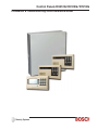
Control Panels D9412G/D7412G/D7212G
Installation & Troubleshooting Quick Reference Guide
D9412G/D7412G/D7212G
Installation & Troubleshooting Quick Reference Guide
D9412G/D7412G/D7212G Installation & Troubleshooting Quick Reference Guide
43700F
Page 2
© 2004 Bosch Security Systems, Inc.
D9412G/D7412G/D7212G
Contents
Table of Contents
1.0
1.1
1.2
2.0
3.0
3.1
3.2
3.3
3.4
3.5
3.6
3.7
3.7.1
3.8
3.8.1
3.9
3.10
3.11
3.12
3.13
3.14
3.15
3.16
3.16.1
3.17
4.0
4.1
4.2
4.3
4.4
4.5
4.6
4.7
4.8
4.9
Introduction .............................................................................................................................................................................................5
Manual Organization .......................................................................................................................................................................... 5
Other Literature Referenced ............................................................................................................................................. 5
Quick Reference Terminal Description ...................................................................................................................................... 7
Troubleshooting .................................................................................................................................................................................... 9
Introduction ............................................................................................................................................................................. 9
Problems Found During Self Diagnostics ....................................................................................................................... 9
Problems Programming the Panel .................................................................................................................................. 10
Problems With Command Centers ................................................................................................................................ 11
Phone Line Trouble ............................................................................................................................................................. 11
Communication Failure ..................................................................................................................................................... 12
Problems with Points .......................................................................................................................................................... 13
Extra Points ........................................................................................................................................................................... 14
Problems with the D8125 POPEX Data Expansion Loops ...................................................................................... 15
Metering the Loops ............................................................................................................................................................ 15
EMI on Long Wire Runs ................................................................................................................................................... 16
Checking Shielded Cable ................................................................................................................................................ 16
Battery and Power Reports .............................................................................................................................................. 16
Watchdog Reset Reports ................................................................................................................................................. 17
Runaway Reports to the Receiver ................................................................................................................................. 17
Overloaded Power Supply ................................................................................................................................................ 17
Service Walk Test ............................................................................................................................................................... 18
Ground Fault ....................................................................................................................................................................... 2 0
Procedure for Isolating Earth Ground Faults ............................................................................................................... 20
Panel Buzzer ......................................................................................................................................................................... 21
System Wiring Diagrams, Issue A ............................................................................................................................................ 23
D9412G Control Panel, 1 of 3 ...................................................................................................................................... 2 3
D9412G Control Panel, 2 of 3 ...................................................................................................................................... 2 4
D9412G Control Panel, 3 of 3 ...................................................................................................................................... 2 5
D7412G Control Panel, 1 of 3 ...................................................................................................................................... 2 6
D7412G Control Panel, 2 of 3 ...................................................................................................................................... 2 7
D7412G Control Panel, 3 of 3 ...................................................................................................................................... 2 8
D7212G Control Panel, 1 of 3 ...................................................................................................................................... 2 9
D7212G Control Panel, 2 of 3 ...................................................................................................................................... 3 0
D7212G Control Panel, 3 of 3 ....................................................................................................................................... 31
D9412G/D7412G/D7212G Installation & Troubleshooting Quick Reference Guide
© 2004 Bosch Security Systems, Inc.
Page 3
43700F
D9412G/D7412G/D7212G
Contents
Figures
Figure 1: Service Walk Test Flow Chart ....................................................................................................................................... 19
Figure 2: D9412G System Wiring Diagram ................................................................................................................................ 23
Figure 3: D9412G System Wiring Diagram ................................................................................................................................ 24
Figure 4: D9412G System Wiring Diagram ................................................................................................................................ 25
Figure 5: D7412G System Wiring Diagram ................................................................................................................................ 26
Figure 6: D7412G System Wiring Diagram ................................................................................................................................ 27
Figure 7: D7412G System Wiring Diagram ................................................................................................................................ 28
Figure 8: D7212G System Wiring Diagram ................................................................................................................................ 29
Figure 9: D7212G System Wiring Diagram ................................................................................................................................ 30
Figure 10: D7212G System Wiring Diagram .............................................................................................................................. 31
Tables
Table 1: Chapter Summary ................................................................................................................................................................ 5
Table 2: Referenced Literature ......................................................................................................................................................... 5
Table 3: Quick Reference Terminal Description ........................................................................................................................... 7
Table 4: Troubleshooting Problems Found During Self Diagnostics ....................................................................................... 9
Table 5: Troubleshooting Problems Programming the Panel ................................................................................................... 10
Table 6: Troubleshooting Command Center Problems ............................................................................................................. 11
Table 7: Troubleshooting Phone Line Problems ......................................................................................................................... 11
Table 8: Troubleshooting Communication Failures .................................................................................................................... 12
Table 9: Troubleshooting Problems with Points .......................................................................................................................... 13
Table 10: Data Expansion Loop Wire Specifications ............................................................................................................... 15
Table 11: Terminal Grouping Ground Fault ................................................................................................................................. 20
D9412G/D7412G/D7212G Installation & Troubleshooting Quick Reference Guide
43700F
Page 4
© 2004 Bosch Security Systems, Inc.
D9412G/D7412G/D7212G
Introduction
1.0
Introduction
This reference contains the very basic information a trained installer needs to install and troubleshoot a D9412G, D7412G, or
D7212G Control Panel system.
1.1
Manual Organization
This manual is divided into four sections, which are summarized in Table 1.
Section No.
1
2
2
4
Description
Introduction – information about organization of the manual and additional
literature that may be ordered.
Quick Reference Terminal Description – description of panel terminals
presented in a quick reference table.
Basic Troubleshooting – basic troubleshooting solutions and procedures to
resolve common problems during programming and installation of the
D9412G, D7412G, and D7212G Control Panels.
System Wiring Diagrams, Issue A – reference drawings showing the wiring
diagrams for the D9412G, D7412G, and D7212G Control Panels.
Table 1: Chapter Summary
D9412G/D7412G/D7212G Installation & Troubleshooting Quick Reference Guide
© 2004 Bosch Security Systems, Inc.
Page 5
43700F
D9412G/D7412G/D7212G
Introduction
1.2
Other Literature Referenced
For a more complete and detailed description of the D9412G/D7412G/D7212G Control Panels, see the additional literature
referenced by part number for easy ordering in Table 2.
Document Name
D1255 Installation Instructions
D1256/D1257 Installation Instructions
D1260 Installation Guide
D1260 Owner’s Manual
D5200 Operation Manual
D720 Installation Instructions
D7212G Approved Applications Compliance Guide
D7212G Operation and Installation Guide
D7212G Program Entry Guide
D7212G Program Record Sheet
D7212G Release Notes
D7412G Release Notes
D8125MUX Operation and Installation Guide
D9210B Operation and Installation Guide
D9412G Release Notes
D9412G/D7412G Approved Applications Compliance Guide
D9412G/D7412G/D7212G Installation and Troubleshooting Quick Reference Guide
D9412G/D7412G New Features
D9412G/D7412G Operation and Installation Guide (this manual)
D9412G/D7412G/D7212G Point Chart Label
D9412G/D7412G Program Entry Guide
D9412G/D7412G Program Record Sheet
RAM IV Operations Manual
Security System Owner's Manual
Security System Owner's Manual Supplement
UL Certificated Bank Safe and Vault Applications Technogram
9000/9000G Series Smoke Detector Compatibility List
Part Number
74-06819-000
74-06925-000
48101
50410
74-06176-000
74-06918-000
4998138560
4998138544
4998138538
4998138542
4998138543
43856
36796
32206
43821
43494
43700
43746
43488
79-06660-000
47775
47488
38849
71-06633-000
33267
73-07302-000
33284
Table 2: Referenced Literature
D9412G/D7412G/D7212G Installation & Troubleshooting Quick Reference Guide
43700F
Page 6
© 2004 Bosch Security Systems, Inc.
D9412G/D7412G/D7212G
Quick Reference Terminal Description
2.0
Quick Reference Terminal Description
Terminal
1, 2
3
Name
CLASS 2
TRANSFORMER
+ AUX POWER
4
BATTERY
NEGATIVE ONLY
5 (+)
BATTERY
POSITIVE ONLY
6 (+)
+ STEADY OR
PULSED ALARM
POWER
+ ALTERNATE
ALARM POWER
7 (+)
8 (+)
+ SWITCHED
AUX POWER
9
COMMON
10
EARTH GROUND
11, 13, 14,
16, 17, 19,
20, 22
12, 15, 18,
21
24 (+)
ON-BOARD
POINTS
(Inputs)
ON-BOARD
POINTS
(Common)
ZONEX
COMMON
ZONEX POWER +
25
26
27
28
29 (-)
30
31
ZONEX IN 2
ZONEX OUT 2
ZONEX IN 1
ZONEX OUT 1
COMMON
DATA BUS B
DATA BUS A
32 (+)
POWER +
23 (-)
Description
Connect 16.5 VAC, 40 VA transformer for primary power supply.
Supplies up to 1.4 A at 10.2 VDC to 13.9 VDC to powered devices. Use Terminal
9 for common. Shares PTC with Terminal 24.
Connect rechargeable lead acid type battery’s negative terminal (-) to Terminal
4. (See the Current Rating Charts section in the panel’s Approved Applications
Compliance Guide to determine battery size requirements.)
Connect rechargeable lead acid type battery’s positive terminal (+). (See the
Current Rating Charts section in the panel’s Approved Applications Compliance
Guide to determine battery size requirements.)
Supplies up to 2 A at 10.2 VDC to 13.9 VDC for steady or pulsed alarm output.
Use Terminal 9 for common. Programmed as Relay A. Shares PTC with
Terminals 7 and 8.
Supplies up to 2 A at 10.2 VDC to 13.9 VDC for steady or pulsed alarm output.
Use Terminal 9 for common. Programmed as Relay B. Shares PTC with
Terminals 6 and 8.
D136 Plug-in Relay required: Install a D136 in the ALT ALARM socket for
output at Terminal 7.
Supplies up to 1.4 A at 10.2 VDC to 13.9 VDC. Use Terminal 9 for common.
Programmed as Relay C. Continuous output interrupted by RESET SENSORS
or alarm verification. Shares PTC with Terminals 6 and 7.
D136 Plug-in Relay required: Install a D136 in the SW AUX socket for output at
Terminal 8.
Terminal 9 is common for Auxiliary Power, Steady or Pulsed Alarm Power,
Alternate Alarm Power, and Switched Aux Power (Terminals 3, 6, 7, and 8).
Connect to earth ground. A cold water pipe or grounding rod is preferred.
Do not connect to telephone or electrical ground.
Connect normally open and/or normally closed detection devices to loop wiring.
1 kΩ resistor required at end of loop.
Loop returns for on-board points.
[D9412G only] Use Terminals 23 and 24 to power ZONEX modules such as
the
D8125 POPEX module, the D8128D OctoPOPIT, and the D8129 OctoRelay.
Shares PTC with Terminal 3.
[D9412G only] Connect ZONEX modules for Points 129 to 247 and Relays
65 to 128 to these terminals.
Connect ZONEX modules for Points 9 to 127 and Relays 1 to 64 to these
terminals. (The D7412G uses Points 9 to 75, the D7212G uses Points 9 to 40.)
Common terminal for SDI devices.
Terminals 30 and 31 are a two-wire bus that drives the command centers,
printer interface, and access control modules including the D9133TTL-E
Ethernet Interface Module, D9133DC Direct Connect Module, D9133 Serial
Interface Module, and the PC9133TTL-E Ethernet Interface Module.
Power for SDI devices. Shorts on any other terminal do not affect this separate,
protected power output for SDI devices.
Table 3: Quick Reference Terminal Description
D9412G/D7412G/D7212G Installation & Troubleshooting Quick Reference Guide
© 2004 Bosch Security Systems, Inc.
Page 7
43700F
D9412G/D7412G/D7212G
Quick Reference Terminal Description
Notes:
D9412G/D7412G/D7212G Installation & Troubleshooting Quick Reference Guide
43700F
Page 8
© 2004 Bosch Security Systems, Inc.
D9412G/D7412G/D7212G
Troubleshooting
3.0
Troubleshooting
3.1
Introduction
Bosch Security Systems provides this guide to help troubleshoot problems with the D9412G/D7412G/D7212G. To prevent
problems from occurring, read the preceding sections of this guide and the panel’s Program Entry Guide to verify that the
panel is correctly installed and programmed.
3.2
Problems Found During Self Diagnostics
The D9412G/D7412G/D7212G Control Panels perform a series of self-diagnostic tests of hardware, software, and program
at start up and reset.
Buzzer sounding is normal at start-up: The on-board buzzer located on the lower right corner of the panel sounds as the
control/ommunicator performs its self diagnostic tests at start up and reset. The tests take less than two seconds. If all tests
are completed successfully, the buzzer turns off. The panel continues periodic internal testing during normal operation. If a
fault is detected during this testing, the buzzer begins sounding. One of the system messages listed below displays at the
command centers.
Symptom
CALL FOR SERVICE appears in
the command center's display. No
buzzer sounds at the Command
Center.
COMM FAIL ROUTE # appears in
command center displays.
Diagnosis
A command center has
stopped receiving data
from the panel.
Remedy
Check the wiring for opens, grounds, or shorts.
The panel has made ten
unsuccessful attempts
to report to the receiver.
PANEL BROKEN appears in the
displays of all command centers, the
command center buzzer sounds, and
the green operation monitor LED
stops flickering or is off.
PARAM FAIL alternates with the
idle text at the command centers, the
command center buzzer sounds, the
green operation monitor LED
continues to flicker, and the panel
sends a BAD PARAM CKSUM report
to the receiver.
SERVC AC FAIL appears in
command center displays.
A hardware or software
problem has occurred.
See Section 3.6 Communication Failure on page
12. Pressing [ESC] silences the buzzer. The
display clears when communication restores (i.e.,
the receiver acknowledges a report).
Pressing [ESC] does not silence the buzzer. The
panel must be returned to Bosch Security
Systems for repair.
The program is
corrupted.
Pressing [ESC] may silence the buzzer.
Silencing the buzzer does not correct the problem:
The corrupted copy of the program in the panel
must be replaced. Load a new copy of the
complete program. The displays clear when the
panel is reset after loading a new program.
AC power has been
interrupted at
Terminals 1 and 2.
Pressing [ESC] silences the buzzer. Restoring
power clears the display.
NOTE: You can program the panel to send an AC
FAIL report to the receiver.
See Section 3.11 Battery and Power Reports on
page 16 for probable causes and remedies.
Pressing [ESC] silences the buzzer. The display
clears when battery voltage reaches 13.7 VDC.
Pressing [ESC] silences the buzzer. Restoring the
battery clears the display.
NOTE: The panel can be programmed to send a
BATTERY MISSING report to the receiver.
SERVC BATT LOW appears in
command center displays.
Battery voltage at
Terminals 4 and 5 has
fallen below 12.1 VDC.
SERVC BATT MSING appears in
command center displays.
The panel cannot detect
a battery at Terminals 4
and 5.
Table 4: Troubleshooting Problems Found During Self Diagnostics
D9412G/D7412G/D7212G Installation & Troubleshooting Quick Reference Guide
© 2004 Bosch Security Systems, Inc.
Page 9
43700F
D9412G/D7412G/D7212G
Troubleshooting
Symptom
SERVC GND FAULT appears in
command center displays.
Diagnosis
The panel has
detected an earth
ground fault.
SERVC KEY PAD appears at
other command centers
connected to the panel.and the
panel transmits an SDI
FAILURE report to the receiver.
SERVC 9210 #n appears at the
other command centers
connected to the panel and the
panel transmits an SDI
FAILURE ## report to the
receiver.
SERVC PH LINE #1 (or
SERVC PH LINE #2 if two
lines are used) appears in
command center displays.
SERVC PRINTER appears in
command center displays.
The panel has lost
contact with a
supervised command
center.
Remedy
Follow the steps in Section 3.16.1 Procedure for
Isolating Earth Ground Faults on page 20. See Section
3.5 Connecting Earth Ground in the D9412G/D7412G
Operation and Installation Guide (P/N: 43488).
Pressing [ESC] silences the buzzer. The displays clear
when contact with the missing Command Center
restores.
The panel has lost
contact with a
D9210B Access
Interface Module.
Check the wiring for opens, grounds, or shorts.
The panel has
detected a phone line
as faulted.
See Section 3.5 Phone Line Trouble on page 11.
See Section 6.8 Phone Line Monitor in the
D9412G/D7412G Operation and Installation Guide
(P/N: 43488) for a complete description.
Pressing [ESC] silences the buzzer. The displays clear
when contact with the missing printer restores.
The panel has lost
contact with a
supervised printer.
Table 4 (cont’d): Troubleshooting Problems Found During Self Diagnostics
3.3
Problems Programming the Panel
Before attempting to program the panel, become familiar with the basic operation of the D5200 programmer. See the D5200
Operation Manual (P/N: 74-06176-000). If problems are still experienced, check for the symptoms below:
Symptom
The programmer displays
PLUG IN PANEL when you
press [SEND] or [RECEIVE].
After plugging in the
programmer, the panel transmits
SDI TROUBLE reports for
supervised SDI devices (command
centers, Printer Interface
Modules, etc.). All SDI devices
stop operating.
Diagnosis
The programmer is
not correctly
connected to the
panel.
AC induction
through the on-board
point sensor loops,
the DATA bus, or the
ZONEX bus.
You must lock the
rest pin when
programming the
panel with a D5200.
Remedy
Verify that the data/power cord is plugged into the
COMMUNICATOR port on the D5200.
Verify that the data/power cord is plugged securely
into the panel’s Programmer Connector.
Check each conductor in the data/power cord for
continuity.
Verify a proper earth ground at Terminal 10.
Disconnect on-board point sensor loops, the DATA
bus (Terminals 30 & 31), and the ZONEX bus
(Terminals 25 – 28).
Lock the reset pin.
Table 5: Troubleshooting Problems Programming the Panel
D9412G/D7412G/D7212G Installation & Troubleshooting Quick Reference Guide
43700F
Page 10
© 2004 Bosch Security Systems, Inc.
D9412G/D7412G/D7212G
Troubleshooting
3.4
Problems With Command Centers
Symptom
Command centers show erratic
behavior. For example, the pip
that confirms you pressed a key
echoes.
NO AUTHORITY displays at the
command center when you enter
your passcode to perform a
function.
Diagnosis
Remedy
More than one
Use a supervised address in one command center only
command center has
or use a different supervised address for each
the same supervised
command center.
address.
Check that yellow and green data wires are correctly
Data connections
connected on all command centers.
(yellow and green
wires) on one or
more command
centers are reversed,
or only one wire is
connected.
Check the User Interface section of the program to be sure the function is
enabled for the authority level assigned to the passcode in the Passcode
Worksheet section of the program.
Check the Passcode Worksheet section of the program to be certain the passcode
is assigned to the area where you are attempting to perform the function.
Check the Passcode Worksheet section of the program to see if the passcode is
restricted by a user window.
Check the Area Parameters section of the program to be certain the area in
which you are attempting to perform the function is turned on.
Table 6: Troubleshooting Command Center Problems
3.5
Phone Line Trouble
Phone line problems that are not corrected can result in the panel going into Communications Failure. The D9412G/D7412G
can be programmed to monitor one or two phone lines. See the D9412G/D7412G Program Entry Guide (P/N: 47775) for
programming instructions. If the phone line monitor is enabled, SERVC PHONE LINE #1 (or SERVC PHONE LINE
#2 if two lines are used) appears in the command center’s display when the panel detects a problem on the phone line.
System
SERVC PH LINE #1 (or
SERVC PH LINE #2 if two
lines are used) appears in the
command center display.
Diagnosis
The panel’s phone line
monitor detects a phone
line as faulted.
Remedy
Verify that the telephone cord is correctly
connected to the phone jack and the panel.
Verify the Ground Start Jumper is in the correct
position.
If using a ground start phone line, verify a D136
relay is correctly installed in the Ground Start Relay
socket.
Verify that the phone jack (RJ31X or RJ38X) is
wired correctly. The incoming phone line must be
wired to Terminals 4 and 5. The in-house phone
system must be wired to Terminals 1 and 8.
Verify that all telephones are on-hook. Leaving a
telephone on hold after the other party hangs up
creates an off-hook condition. Verify that no
phones are on-hold.
If completing the steps above does not restore the
phone line, meter the line. You should meter at
least 3.0 VDC. If your readings are below the
minimum values, contact your telephone company
repair service.
Table 7: Troubleshooting Phone Line Problems
D9412G/D7412G/D7212G Installation & Troubleshooting Quick Reference Guide
© 2004 Bosch Security Systems, Inc.
Page 11
43700F
D9412G/D7412G/D7212G
Troubleshooting
3.6
Communication Failure
The panel goes into Communication Failure after ten unsuccessful attempts to reach the receiver. Follow the procedure in
Section 3.5 Phone Line Trouble on page 11 to verify that there is no problem with the phone lines at the installation. If the
phone lines are good, monitor the lines (preferably at the receiver) for the symptoms listed below.
Symptom
Diagnosis
Remedy
Line is not ringing at
Verify that the lines are correctly connected to the
The line rings but the D6500
the receiver.
receiver.
receiver does not pick up. The
Verify that correct prefixes and phone numbers for the
Ring indicator LED on line card
receiver have been programmed into the panel.
does not light. You cannot hear
If completing the steps above does not correct the
ring with headset at receiver
problem, contact your telephone company repair
location.
service.
The panel is unable to call out
The total current
Put command centers on a separate power supply to
when all 246 points are faulted.
draw is too much for
get maximum current draw from points in alarm.
the panel.
The line rings but the receiver
Line card in receiver
Review receiver manuals for troubleshooting
does not pick up. The Ring
may be faulty.
procedures.
Indicator LED on line card lights.
You can hear ring with test set at
receiver location.
The panel reaches a busy signal for Calls are not reaching Verify that correct prefixes and phone numbers for the
all ten attempts to reach the
the receiver.
receiver have been programmed into the panel.
receiver.
Verify that the phone lines are not shorted between the
phone company's equipment and the receiver by
placing a call to the number for the receiver. If you
hear the line ring, but the ring detector doesn't light,
or if you hear a busy signal and the green on line (OL)
indicator is not lit, call the phone company for service.
The receiver's call
Additional line cards and phone lines may be needed
load is too great.
for the receiver
The receiver answers the call and
The receiver is not
Verify that the receiver is producing a 1400 Hz, 2300
provides an acknowledgment
producing the correct Hz, or Modem IIIa2 acknowledgment tone.
tone, but the communicator does
acknowledgment
not transmit reports.
tone.
Panel does not connect to central
The D136 relay used
Insert the D136 relay in the GND STARTsocket
station.
for ground start
correctly. Also check that phone line is connected and
phone systems is
that phone jack is wired properly. See the Ground Start
inserted incorrectly.
section in the panel’s Operation and Installation Guide
for instructions.
Verify that the receiver is compatible with the format
The receiver answers the call and
The receiver is not
the panel is using (either BFSK or Modem IIIa2
provides an initial “handshake”
compatible with the
acknowledgment, but does not
panel’s transmission
Communications Format). See the Telephone
acknowledge the panel’s report
format.
Connections section in the panel’s Program Entry
transmission with a “kiss-off”
Guide.
acknowledgment.
The panel requires D6500 MPU and Line Card
EPROM revision 8.00 or higher.
Noisy phone lines are Try making a voice call to the receiver on the line to
verify the noisy condition. It may be necessary to have
interfering with
the phone company check the lines.
report transmission.
Table 8: Troubleshooting Communication Failures
D9412G/D7412G/D7212G Installation & Troubleshooting Quick Reference Guide
43700F
Page 12
© 2004 Bosch Security Systems, Inc.
D9412G/D7412G/D7212G
Troubleshooting
3.7
Problems with Points
If the switches on a POPIT are set incorrectly, it may create both a missing and extra point. When a missing point is found,
perform a Service Walk Test to search for extra points. See the Owner’s Manual for test instructions.
Symptom
Point appears as missing at
command centers and in reports
to the receiver.
Diagnosis
POPIT is not
connected or
incorrectly connected
to the data expansion
loop.
D8128C OctoPOPIT
is installed at the last
address on the
ZONEX bus.
Sensor loop switch (1
to 8) is turned off on
D8128D OctoPOPIT.
POPIT is not
programmed
correctly.
Points intermittently appear as
missing. Points are erratic.
One or more points remain in
trouble or alarm with all devices
connected to the sensor loops
normal.
Faulted points do not generate
alarms or troubles as
programmed.
Problem with data
expansion loop.
Debounce Count
parameter set at 1. If
an off-board point is
in transition between
normal and faulted
conditions as the
panel scans it, it
appears as missing.
The sensor loop is
open, shorted, or
grounded.
Opens, shorts, or
grounds cause
troubles or alarms
depending on point
programming.
Sensor Reset pressed
at the time the alarm
or trouble was
generated.
Two points are
programmed with the
same address.
Remedy
Verify that a POPIT module programmed for the
missing point number is connected to the data
expansion loop of the correct ZONEX module. Points
9 to 127 connect to ZONEX module 1. Points 129 to
247 connect to ZONEX module 2.
Meter each POPIT to verify the polarity of the data
expansion loop. Voltage should be 9 to 13 VDC at
each POPIT.
Install a D8125 POPEX and D9127 POPITs for points
121-127 on ZONEX 1 and for points 241-247 on
ZONEX 2 when using D8128C OctoPOPITs.
If the sensor loop switch on D8128D OctoPOPIT is
turned off for a programmed point, the point reports
as missing.
Verify that the switches on the POPIT are set for the
missing POPIT number. Switches set incorrectly can
cause both missing and extra POPITs.
Performing a Service Walk Test to search for extra
points may help diagnose the problem.
See Section 3.8 Problems with the D8125 POPEX Data
Expansion Loops on page 15.
It is recommended that the Debounce Count be left at
the default of 2.
Decreasing the Debounce Count to 1 may cause points
to appear as missing. Increasing the Debounce may
cause missed alarms.
Remove the sensor loop from the panel or POPIT and
meter it for continuity. There should be no more than
100 Ω resistance, plus the value of the end of line
resistor on the wires. If you meter less resistance than
the value of the end of line resistor, check the wiring
for shorts.
With the wires for the loop removed, meter them for
continuity to ground. See Section 3.16 Ground Fault
on page 20 for additional information.
The panel ignores input from all points in the same
area programmed for sensor reset during sensor reset.
Points programmed with the same address do not
function correctly. Check to be certain that you have
not duplicated point addresses.
Table 9: Troubleshooting Problems with Points
D9412G/D7412G/D7212G Installation & Troubleshooting Quick Reference Guide
© 2004 Bosch Security Systems, Inc.
Page 13
43700F
D9412G/D7412G/D7212G
Troubleshooting
System
Panel transmits PT BUS
TROUBLE reports.
Erroneous alarm and/or
trouble reports may follow
PT BUS TROUBLE report.
Erroneous alarm and/or
trouble events for off-board
points appear at command
centers.
All off-board points are
MISSING.
Keyswitch points (P## Type
is programmed as 4, 5, 6, 7,
or 9) report as missing. If
area is armed, the point
reports a MISSING
ALARM. If the area is
disarmed, the point reports a
MISSING TROUBLE.
Connected points show as
extra points when the point
bus is shorted beyond the
programmed debounce time.
Diagnosis
Short on D8125 POPEX
module’s Data Expansion
Loop or short on panel’s
ZONEX data terminals (25
& 26, or 27 & 28).
The POPIT address switches
are set incorrectly (for
points 128 or 248) or the
OctoPOPIT address switches
are set incorrectly.
Short on Aux Power,
terminal 3 or ZONEX
power, terminal 24.
If only one POPEX module
is connected to the panel,
POPEX module may be
incorrectly connected to the
panel or Data Expansion
Loop may be disconnected
from POPEX module.
Point is disconnected from
the Popit data bus.
The POPIT cover may have
been removed and not
replaced or the cover is not
seated properly.
The points have no point
index programmed.
Remedy
A short on either the Data Expansion Loop or
the ZONEX data terminals generates a PT BUS
TROUBLE report.
While the short remains, the panel responds as
though the sensor loop for each point connected
to the POPEX module was shorted.
Check wiring for shorts.
Check to be certain all POPIT and OctoPOPIT
address switches are set correctly. POPITs cannot
be used for points 128 or 248 (these are reserved
for panel functions). D8128C OctoPOPITs
cannot be used for Points 121-128 or 241-248.
D8128D OctoPOPITs cannot use Points 128 or
248.
Terminals 3 and 24 share a common circuit
breaker. Check wiring and devices connected to
these terminals for shorts or grounds.
Check POPEX module for correct connections
to the panel and the Data Expansion Loop.
If you find missing points, the service walk test
may help you diagnose the problem (see Section
3.7.1 Extra Points).
The point will restore when the Popit bus is
reconnected or when the POPIT cover is seated
firmly on the POPIT.
This will be corrected when the short is returned
to normal.
Table 9 (cont’d): Troubleshooting Problems with Points
3.7.1
Extra Points
If the panel is not in the service walk test mode when an extra point trips, the panel responds to it as a local TROUBLE event
at the command center or central station (see Routing in the panel’s Program Entry Guide). It displays the custom text for the
point number set in the point’s dipswitch or on-board point location.
When an extra point is tripped during the service walk test, it reports as an EXTRA point in the panel’s event log and at the
local printer (if installed). Once an extra point is identified, check the programming to see if it has a Point Index
programmed and if so, if the point index is appropriate for the application and has the correct area assignment.
D9412G/D7412G/D7212G Installation & Troubleshooting Quick Reference Guide
43700F
Page 14
© 2004 Bosch Security Systems, Inc.
D9412G/D7412G/D7212G
Troubleshooting
3.8
Problems with the D8125 POPEX Data Expansion Loops
EMI (Electro-magnetic Interference), excessive resistance, or intermittent grounds, shorts, or opens on the data expansion
loop can cause erratic or intermittent functioning of points. If EMI may be a problem, see Section 3.9 EMI on Long Wire
Runs on page 16. AC induction on the data expansion loops must be less than 1.0 VAC. If EMI is not suspected as the cause
of the problem, follow the procedures below to find the source of problems on the data expansion loop or use the Zonex
Point Identification Validation Process (P/N: 43049) for a detailed procedure and worksheets to identify and validate all
points.
3.8.1
Metering the Loops
Before following the procedures below to meter the data expansion loops, check Table 10 to verify the correct gauge wire for
the length of the data expansion loops was used.
Maximum Length of all Data
Expansion Loops Combined
AWG
Length in ft. (m)
22
1800 (548)
20
2890 (881)
18
4600 (1402)
16
7320 (2231)
14
11650 (3551)
Table 10: Data Expansion Loop Wire Specifications
When metering the loop, monitor it long enough to observe an intermittent problem.
To meter the data expansion loop without POPITs connected to it:
1.
Disconnect the loop from the POPEX Module.
2.
Twist the positive and then the negative wires together at each POPIT location so that the positive and negative
wires are continuous to the last POPIT location.
3.
At the last POPIT location twist the end of the positive wire to the negative wire to form one continuous loop.
4.
Meter the loop for continuity from the point where it connected to the POPEX Module. Resistance for the
entire loop must be less than 60 Ω. If there is no continuity, find and repair the open on the loop.
5.
Still metering for continuity, untwist the negative and positive wires at the last POPIT location. If the meter
does not show an open condition, find and repair the short on the loop.
6.
Twist the positive and negative wires at the last POPIT location back together.
7.
Meter the loop for continuity to Terminal 10 (earth ground). If there is continuity, find and remove the foreign
ground on the loop.
8.
Meter the loop to Terminal 10 for AC voltage. AC induction on data expansion loops must be less than 1 VAC.
Try using shielded cable to reduce AC induction if the AC voltage exceeds 1 VAC.
D9412G/D7412G/D7212G Installation & Troubleshooting Quick Reference Guide
© 2004 Bosch Security Systems, Inc.
Page 15
43700F
D9412G/D7412G/D7212G
Troubleshooting
3.9
EMI on Long Wire Runs
EMI (ElectroMagnetic Interference) can cause problems on long wire runs for serial devices (command centers, POPITs,
etc.). The use of shielded cable reduces the effect of this interference. Some potential sources of noise on a long wire run
include:
• Radio or television transmitter site.
• Ham radio operator’s transmitter site.
• Computer network system.
• Heavy machinery (large electrical motors).
• PBX telephone system.
• High voltage electrical equipment or transformers (arc welders, certain medical and dental equipment, etc.).
• Public service office using radio communications (fire department, police department, etc.).
• Close proximity to electrical lines, telephone cabling, or fluorescent lighting fixtures.
There are many other possible sources of noise. If noise may be a problem, the use of shielded wire is strongly
recommended. Connect the drain wire from the shielded cable to Terminal 10 on the panel.
The drain wire must have continuity from the panel to the last device on the wire run. If the cable is cut to install devices
between the last device and the panel, be certain to reconnect the drain wire to insure continuity to the last device.
If continuity is not maintained between the panel and the last device, the shielded cable may aggravate potential noise
problems rather than eliminate them. Connecting the drain wire to ground at other than Terminal 10 on the panel may also
produce problems. Do not connect the drain wire to any other ground source.
3.10
Checking Shielded Cable
If improperly installed, shielded cable can create problems rather than solve them. Follow the procedure below to check
shielded cable for proper installation:
3.11
1.
Remove the drain wire for the shield from Terminal 10.
2.
Meter the drain wire for continuity to Terminal 10 (earth ground). If there is continuity, find and remove the
foreign ground on the drain wire.
3.
Reconnect the drain wire to Terminal 10.
4.
Meter the shield at the far end of the cable (last POPIT location on data expansion loops) for continuity to a
ground reference. If there is no continuity, find and repair the open in the shield. Solder and tape all
connections.
Battery and Power Reports
The panel can be programmed to transmit both battery and AC power status reports. Refer to the panel’s Program Entry
Guide. If battery or AC power reports are a problem check the following:
1.
Check to be sure the panel's power supply is not overloaded. Review Section 2.0 Quick Reference Terminal
Description on page 7 and Section 3.14 Overloaded Power Supply on page 17.
2.
Verify that there is at least 16.5 VAC on Terminals 1 and 2.
3.
The outlet the transformer is plugged into should meter between 110 VAC and 120 VAC.
4.
Verify the output for the transformer connected to Terminals 1 and 2 is rated for 16.5 VAC and at least 40 VA.
5.
Disconnect the transformer from Terminals 1 and 2 and meter the battery at Terminals 3 and 4. A fully charged
battery will show approximately 13.8 V.
6.
Make sure the battery is a 12 V sealed lead acid type. It should be rated at 7 Ah or greater, depending on the
NFPA classification of the installation.
7.
If it takes longer than 60 sec. to detect a missing battery, make sure there is a good earth ground connection.
Also check that there are no external devices that may be inducing voltage.
D9412G/D7412G/D7212G Installation & Troubleshooting Quick Reference Guide
43700F
Page 16
© 2004 Bosch Security Systems, Inc.
D9412G/D7412G/D7212G
Troubleshooting
3.12
Watchdog Reset Reports
The panel sends a WATCHDOG RESET report whenever the panel's CPU (Central Processing Unit) is interrupted and has to
start its normal operating sequence over. The on-board buzzer sounds briefly during the Watchdog Reset. The panel returns
to normal operation immediately after resetting.
The most common cause of CPU interruption and WATCHDOG RESET reports is static discharge to the panel. Static
discharges may also corrupt the panel's program. The D9412G/D7412G/D7212G displays a PARAM FAIL message at the
command centers and sends PARM CKSUM FAIL report if the program is corrupted.
Shorting Terminals 3, 6, 7, 8, or 24, or the Programming Connector to ground may also cause a WATCHDOG RESET.
Remove the short to continue normal operation.
A single isolated WATCHDOG RESET report does not mean the panel must be replaced. If experiencing frequent reports,
contact Bosch Security Systems Customer Service for help.
Touch Terminal 10 first: If the on-board buzzer sounds briefly when the panel is first touched, any static charge that is being
carried is being discharged to the panel. The panel may generate WATCHDOG RESET and/or PARAM FAIL events. Always
touch Terminal 10, the panel's earth ground connection, before beginning work on the panel.
Note:
Please note that a WATCHDOG RESET event may be reported after a panel has returned from repair. This is a
normal occurrence and does not necessarily indicate a problem with the panel.
3.13
Runaway Reports to the Receiver
Using the D8128 or D8128A in place of the D8128D OctoPOPIT Module may cause runaway reports to the receiver on AC
failure. Be sure to replace all D8128 or D8128A OctoPOPITS with the D8128D Module.
3.14
Overloaded Power Supply
If the load on the panel's power supply exceeds its capacity, the panel follows a routine to protect itself and the battery. It
sends reports to the Central Station at several points during this routine.
Keep in mind that AC power remains at Terminals 1 and 2 throughout the scenario that follows:
• The panel is operating normally with a good battery, AC is present at Terminals 1 and 2, and auxiliary power
load is under 1.4 A.
• Combined load on Terminals 3, 6, 7, 8, 24, and 32, the Accessory Connector, and the Programming Connector
exceeds and remains above 1.4 A. Device failure or premises wiring ground faults might cause the increased load.
• The panel begins drawing on the battery to support the increased load. The yellow Charging Status LED turns
on.
• The battery begins to drain. When voltage drops to 12.1 V, the panel sends a LOW BATTERY report and turns
on the red Low Battery LED.
• When the battery drops to 10.2 V the panel disconnects it to protect it from deep discharge.
• If AC is still present, the panel removes power to Terminals 3, 6, 7, 8, 24, and 32, and the Programming
Connector to protect its power supply. The green Operation Monitor LED turns off, but the panel is still
operating.
• The panel sends BATTERY MISSING, PT BUS TROUBLE, and SDI FAILURE reports.
• If a D928 Module is connected, it begins sounding.
• After approximately 60 sec. the panel attempts to return to normal operation by returning power to Terminals 3,
6, 7, 8, 24, and 32, and the Programming Connector.
• If the overload condition is still present, the panel removes power.
• The panel attempts to return to normal operation approximately every 60 seconds.
• The cause of the overload is removed. Combined load on Terminals 3, 6, 7, 8, 24, and 32, and the Accessory and
Programming Connectors remains below 1.4 A.
D9412G/D7412G/D7212G Installation & Troubleshooting Quick Reference Guide
© 2004 Bosch Security Systems, Inc.
Page 17
43700F
D9412G/D7412G/D7212G
Troubleshooting
• With the overload removed, the panel returns power to Terminals 3, 6, 7, 8, 24, and 32, and the Programming
Connector. The panel sends PT BUS RESTORAL and SDI RESTORAL reports.
• If a D928 Module is connected, it stops sounding.
• If the battery voltage is below 8.4 V, the panel does not reconnect it. The battery must be replaced.
• When the battery reaches 13.7 V, the panel sends a BATTERY RESTORE report and turns off the red Low
Battery LED.
• When the battery reaches 13.9 V, the panel turns off the yellow Charging Status LED.
3.15
Service Walk Test
The Service Walk Test differs from the standard Walk Test in that POPITs whose switches are set for a point number not
programmed in the panel appear in the test.
The Service Walk Test allows a user to walk test all 246 points from a panel-wide command center, regardless of the point
index type. 246 PTS TO TEST will appear in the D7412G and D7212G Control Panels even though there is a maximum
of only 75 and 40 points available, respectively. Service Walk Tests may also be initiated by account-wide or area-wide
command centers but will only test those points that fall within the scope of the command center that initiated the function.
The Service Walk Test will not test points in areas that are currently armed.
Fire and other 24-hour points do not transmit reports during Service Walk Test!
WARNING
The steps below outline a simple Service Walk Test procedure. The flow chart (Figure 1 on page 19) shows all the Service Walk
Test options.
Note:
1.
Choose a command center to conduct the test. Be certain the display shows the idle disarmed text.
2.
Press the [MENU] key to enter the Function List. Press[NEXT] repeatedly until reaching the
SERVICE WALK ? prompt. Press [ENT]. Or press [9][9] followed by [ENT] to reach the Service Menu to
access the Service Walk Test.
The D7412G and D7212G do NOT include the Service Walk Test in the Service Menu. Therefore, the D7412G and
D7212G must have the Service Walk Test function enabled in the Function List in order for the Service Walk Test to
be accessed.
3.
The display shows ### PTS TO TEST . Test the first detection device.
4.
As the detection devices are faulted, the command center emits a brief tone and displays the point text of the
point tested for 60 seconds. After 60 seconds, the display returns to the points to test message.
Extra Points display default text: If the switches on a POPIT are set incorrectly to a point number that is not in
the program for the panel, the default text for that point number (PT ###) displays when the point is
faulted. The panel’s Program Record Sheet shows the default text for all points.
Faulting the point a second time produces the tone and displays the point text, but does not reduce the PTS TO
TEST count.
Note:
5.
During the Service Walk Test, to see the points that remain untested, press [ESC] when point text is displayed.
The display shows ## PTS TO TEST. Press the [ESC] key. VIEW UNTESTED ? is displayed. Press
[ENT]. ## PTS UNTESTED is displayed. Press [NEXT] to see a list of the points that have not yet been
tested. Move through this list by pressing the [NEXT] key. To resume the Service Walk Test, press [ESC]. ##
PTS UNTESTED is displayed. Press [ESC]. ## PTS TO TEST is displayed. Resume testing points. To end
the Service Walk Test, press [ESC] twice.
6.
After testing the last point, 0 PTS TO TEST displays. Press [ESC]. The display momentarily shows ALL
PTS TESTED before returning to idle text.
The Service Walk Test, when performed on a D7412G and D7212G, cannot display “0 points to test” as it is physically
unable to connect to the second POPEX Module (used for Points 129-247).
Automatic time-out returns the system to idle text: If there is no point or command center activity for 20 min., the
walk test ends automatically. The command center returns to idle text.
D9412G/D7412G/D7212G Installation & Troubleshooting Quick Reference Guide
43700F
Page 18
© 2004 Bosch Security Systems, Inc.
D9412G/D7412G/D7212G
Troubleshooting
SERVICE WALK?
ENT
246 PTS TO TEST
Test a device
ESC
POINT TEXT
(Text displays for 60 seconds)
245 PTS TO TEST
ESC
Test a device
POINT TEXT
(Text displays for 60 seconds)
244 PTS TO TEST
ESC
Test a device
POINT TEXT
1 PTS TO TEST
ESC
Test a device
0 PTS TO TEST
IDLE TEXT
ESC
VIEW UNTESTED?
ENT
# PTS UNTESTED
NEXT
ESC
ESC
POINT TEXT
Figure 1: Service Walk Test Flow Chart
D9412G/D7412G/D7212G Installation & Troubleshooting Quick Reference Guide
© 2004 Bosch Security Systems, Inc.
Page 19
43700F
D9412G/D7412G/D7212G
Troubleshooting
3.16
Ground Fault
If a D9412G/D7412G/D7212G system detects a Ground Fault, considered as a high impedance fault to earth ground of
approximately 100 kΩ or less, the control panel’s command center displays SERVC GND FAULT. Use the following
troubleshooting procedure as a general guideline in identifying and isolating the cause of the earth ground fault.
Please read this procedure carefully before trying to identify the cause of the Ground Fault.
IMPORTANT
3.16.1
Procedure for Isolating Earth Ground Faults
Warning! To prevent personal injury, caution should be observed when identifying whether or not Ground Fault is
on one of the panel power terminals or the Battery terminals. Both are capable of delivering a high current and
have the potential to cause personal damage.
WARNING
1.
With this safety measure in mind, the first step is to verify that the Ground Fault is, or is NOT on the Battery
terminals (terminal 4 and terminal 5). This procedure requires the use of a Digital Volt Meter (DVM) and a
13.0 in. (33 cm) Jumper Wire.
As a point of reference: When a D9412G/D7412G/D7212G Panel is not in GROUND FAULT CONDITION, a
voltage reading between terminal 9 and terminal 10 is 6.5 VDC to 6.8 VDC.
2.
Place a DVM meter on DC Volts scale, and connect the Positive (red) lead of the DVM to Terminal 10 (Earth
Ground) and the Negative (black) lead to Terminal 9 (Common) of the control panel.
If the voltage reading is between 13.70 and 13.88 VDC, STOP! This voltage reading means that the Ground
Fault may be in one of the Panel power circuits such as the Battery, or AUX.
Remove both battery wires from terminal 4 and terminal 5 at the same time. If the voltage across terminals 9
and 10 changes to 6.5 to 6.8 VDC (which indicates a normal reading), then the ground fault is on the battery
wire (or wires). Locate and remove the ground fault.
If the voltage across terminals 9 and 10 still measures between 13.70 and 13.88 VDC, then reconnect the battery
wire(s) back to terminal 4 and terminal 5 and go to Step 3.
3.
If the voltage across terminals 9 and 10 reads 0 VDC, STOP! This voltage reading indicates that the Ground
Fault is on any of the panels’ Common terminals. Remove both battery wires from terminal 4 and terminal 5.
If the voltage across terminals 9 and 10 changes to 6.5 to 6.8 VDC, then the ground fault is on this battery
negative side. Locate and remove the ground. If the voltage across terminals 9 and 10 does not change, then
reconnect both Battery wires to terminal 4 and terminal 5 and go to Step 4.
4.
With the DVM still connected between Terminals 9 and 10, use the following chart to determine which terminal
grouping has the ground fault.
Voltage at Terminals 9 and 10
0 VDC
approximately 1.7 VDC
approximately 2.5 VDC
approximately 7.0 VDC fluctuating
approximately 7.6 VDC fluctuating
approximately 11 to12 VDC
approximately 13.8 VDC
Ground Fault on Corresponding Terminal
4, 9, 12, 15, 18, 21, 23 (D9412G only), and/or 29, 6 and/or 7
6 and/or 7
11, 13, 14, 16, 17, 19, 20, and/or 22,
30 and/or 31
1 and/or 2
25 (D9412G/D7412G only), 26 (D9412G only), and/or 28 (see Step 5)
3, 5, 8, 24 (D9412G only), and/or 32
Table 11: Terminal Grouping Ground Fault
Note:
Terminals 6 and 7 are not energized. Terminal 8 is energized.
D9412G/D7412G/D7212G Installation & Troubleshooting Quick Reference Guide
43700F
Page 20
© 2004 Bosch Security Systems, Inc.
D9412G/D7412G/D7212G
Troubleshooting
5.
Once the voltage has been determined, remove the wire(s) from the terminals listed and verify the voltage on
Terminals 9 and 10 is approximately 6.5 to 6.8 VDC. If the voltage does not measure within this range after
removing the suspected wire, continue to check the remaining wires connected to the terminal group.
To verify that the wire removed has an earth ground short, disconnect the DVM and switch the DVM to read
Ohms. Attach the red lead of the DVM to the end of the wire that was removed (making sure that the
connection is on the conductor of the wire and not the jacket). Attach the black lead of the DVM to Terminal 10
of the control panel. If there is an earth ground short, the reading may be from 0 to 95 kΩ.
Continue troubleshooting the field wiring to eliminate the ground. Begin the process by starting in the middle
of the wire run and checking which side of the wire run has the earth ground short. A known earth ground is
needed for the test.
Once the earth ground fault is isolated, remove the ground, repair the wire, or replace the wire.
6.
3.17
If the voltage being read represents a ground fault on terminals 25, 26, or 28 the ground fault condition may
physically be on either the Zonex Bus, Popit Bus, or an input point on an OctoPopit or Popit. To isolate the
ground fault in this scenario, follow these steps:
a.
Disconnect the positive and negative leads to the battery or batteries.
b.
Connect the jumper wire from Terminal 10 to Terminal 9 for approximately 5 sec.
c.
Points that have a ground fault on the input loop will change to an open state while terminals 9 and 10 are
shorted. DO NOT keep the jumper wire on terminals 9 and 10 for longer than 10 sec. This procedure is
only to be used in tracking down ground fault conditions.
Panel Buzzer
Beginning with revision 6.30 and higher on D9412G/D7412G Control Panels and revision 6.50 and higher on the D7212G
Control Panel, the control panel’s on-board buzzer will pulse 1 sec. on, 1 sec. off, if a supervised command center no longer
responds to polls from the panel. The buzzer will be silenced when the supervised command center begins to respond to
polls again or by pressing a Command 4 from an operational command center.
D9412G/D7412G/D7212G Installation & Troubleshooting Quick Reference Guide
© 2004 Bosch Security Systems, Inc.
Page 21
43700F
D9412G/D7412G/D7212G
Troubleshooting
Notes:
D9412G/D7412G/D7212G Installation & Troubleshooting Quick Reference Guide
43700F
Page 22
© 2004 Bosch Security Systems, Inc.
D9412G/D7412G/D7212G
System Wiring Diagrams, Issue A
4.0
System Wiring Diagrams, Issue A
4.1
D9412G Control Panel, 1 of 3
1
2
3
4
5
D113
CHGRBAT 2BAT 2+
-
+
D126
or
D1218
-
VAUX+
BAT 1-
SUPV
BAT 1+
CHGR+
+
D126
or
D1218
7
D1640
16.5 V, 40 VA
60 Hz
Transformer
-
-
+
D126
or
D1218
8
+
6
10
D126
or
D1218
1
2
D8132
9
D126
Battery
12 V, 7 Ah
or
D1218
12 V, 17.2 Ah
or 18.0 Ah
11
D126
Battery
12 V, 7 Ah
or
D1218
12 V, 17.2 Ah
or 18.0 Ah
D192A/C/D/G
12
AUX PWR
ALARM TRIG
COM
CLASS 2 TRANSFORMER
16.5 VAC 40 VA 60 Hz
Model D1640
Internally Fused - Do Not short
Requires Unswitched Outlet
Do Not Share With Other Equipment
3
+ AUX POWER
4
BATTERY NEGATIVE ONLY
5
Maximum Charging
Current 1.4 Amps.
BATTERY POSITIVE ONLY
6
RELAY A
7
RELAY B
8
RELAY C
PROGRAMMABLE
ALARM OUTPUTS
Terminals
7 & 8
Requires Optional
Model D136 Relay
In ALT ALARM
& SW AUX
SUPV IN
9
COMMON
ALARM CKT
10
-
10 +
EARTH GROUND
GROUND FAULT DETECT
Enabled
Disabled
10
GND START
GROUND START
PHONE
RED
Requires Relay
LED
Model D136 in
ON WHEN
Groun d
COMMU NICATING
Start Socket
OFF WH EN IDLE
7
10
Point 3 Point 4
LOOP START
7
C900
Point 1 Point 2
PHONE MONITOR SELECT
10
D928
11
12
13
14
15
16
Point 8
GND FAULT
Detect
D
E
I
N
S
A
A
B
B
L
L
E
E
PROG
CONN
GRN
10
RJ31X
15
13
RJ31X
16
Figure 2: D9412G System Wiring Diagram, 1 of 3
1 - If required by local AHJ, connect D113 Battery Lead
supervision module.
9 - Refer to the D113 Installation Instructions
(P/N: 74-07468-000) for BATT SUPV
2 - To battery negative
10 - Power limited, supervised
3 - To AUX —
11 - Power limited
4 - To point input
12 - To Relay A or Relay B
5 - To battery positive
13 - Listed audible signaling devices rated at 10.2 VDC to
13.8 VDC (do not use vibrating type horns).
6 - D8004 Transformer Enclosure required for NFPA
applications.
14 - To RJ31X Jack
7 - Optional
15 - 560 Ω, 2W EOL Resistor (P/N: 15-03130-005)
8 - D122 Dual Battery Harness, as required
16 - To earth ground
D9412G/D7412G/D7212G Installation & Troubleshooting Quick Reference Guide
© 2004 Bosch Security Systems, Inc.
Page 23
43700F
D9412G/D7412G/D7212G
System Wiring Diagrams, Issue A
4.2
D9412G Control Panel, 2 of 3
1
2
3
+ AUX POWER
4
BATTERY NEGATIVE ONLY
5
RELAY A
7
RELAY B
8
RELAY C
9
PROGRAMMABLE
ALARM OUTPUTS
Terminals
7 & 8
Requires Optional
Model D136 Relay
In ALT ALARM
& SW AUX
COMMON
VOLTAGE RANGES
Open
3.7 - 5.0 VDC
Normal 2.0 - 3.0 VDC
Short
0.0 - 1.3 VDC
EARTH GROUND
GROUND FAULT DETECT
Enabled
Disabled
-
+
Maximum Charging
Current 1.4 Amps.
BATTERY POSITIVE ONLY
6
10
1
CLASS 2 TRANSFORMER
16.5 VAC 40 VA 60 Hz
Model D1640
Internally Fused - Do Not short
Requires Unswitched Outlet
Do Not Share With Other Equipment
Point 1 Point 2
Point 3 Point 4
Point 5 Point 6
Point 7 Point 8
PHONE MONITOR SELECT
LOOP START
GND START
GROUND START
PHONE
RED
Requires Relay
LED
Model D136 in ON WHEN
Ground
COMMU NICATING
OFF WHEN ID LE
Start Socket
D130
11
12
13
14
15
16
17
18
19
20
21
22
Point 8
GND FAULT
Detect
D
E
I
N
S
A
A
B
B
L
L
E
E
GRN
P105BL
4
P105F
3
D125B
Sw. Aux Pwr
Zone B
Zone A
Pnl Common
Pnl Common
1
2
D129
3
4
Loop B-
5
6
Loop A-
7
Loop B+
5
Loop BLoop BLoop B+
Zone B
2
Aux Power
Loop B+
8
9
Earth Ground 10
Loop A+
1
2
3
4
5
6
Earth Ground
7
Common
8
9
Zone A
10
11
Loop A- 12
Loop A+
Loop A-
Loop A+
13
Figure 3: D9412G System Wiring Diagram, 2 of 3
1-
(Optional): For 24 V applications, use a UL Listed 24 VDC Power Supply with a D130 Relay Module. Refer to the
D130 Operation and Installation Guide (P/N: 74-06262-000) for correct wiring requirements.
2-
To UL Listed two-wire smoke detectors. Refer to the 9000/9000G Series Technical Service Note: Smoke Detector
Compatibility (P/N: 33284) for a listing of compatible two-wire smoke detectors.
3-
P105F, 1 kΩ EOLR (P/N: 15-03130-004): Suitable for un-powered initiating and supervisory devices such as pull
stations, heat sensors, and valve tampers.
4-
P105BL, 1 kΩ EOLR (P/N: 15-03130-004): For typical burglar alarm applications.
5-
D129 provides optional Waterflow Retard feature. Not suitable for two-wire smoke detectors.
(Note: Use Zero Retard except for waterflow devices.)
D9412G/D7412G/D7212G Installation & Troubleshooting Quick Reference Guide
43700F
Page 24
© 2004 Bosch Security Systems, Inc.
D9412G/D7412G/D7212G
System Wiring Diagrams, Issue A
4.3
D9412G Control Panel, 3 of 3
D1255
D1256
1
D1260
D1257
PERIPHERAL DEVICE CONNECTIONS
POWER +
32
YELLOW
DATA BUS A
31
GREEN
DATA BUS B
30
BLACK
COMMON
29
ZONEX OUT 1
28
ZONEX IN 1
27
RED
3
3
N.F.P.A.
Style 3.5
Signaling
Line
Circuits
3
3
D9210B
3
1
D9131A
2
3
Point 8
GND FAULT
Detect
D
E
I
N
S
A
A
B
B
L
L
E
E
ZONEX OUT 2
26
ZONEX IN 2
25
ZONEX POWER +
24
ZONEX COMMON
23
3
3
4
PROG
CONN
D9133TTL-E
GRN
D8125
+
3
D8125
5
-
+
7
D8128D
8
D8128D
9
D8129
10
D8129
11
6
-
7
Figure 4: D9412G System Wiring Diagram, 3 of 3
1-
Up to eight supervised D9210Bs
2-
Up to three supervised D9131As
3-
7-
Up to 119 D9127U/T POPITs or up to 63
D8127U/T POPITs.
Power limited, supervised
8-
Zx 1: 15 D8128Ds
4-
Power limited
9-
Zx 2: 15 D8128Ds
5-
POPEX #1
10 -
Zx 1: Up to eight D8129s maximum
POPEX #2
11 -
Zx 2: Up to eight D8129s maximum
6-
D9412G/D7412G/D7212G Installation & Troubleshooting Quick Reference Guide
© 2004 Bosch Security Systems, Inc.
Page 25
43700F
D9412G/D7412G/D7212G
System Wiring Diagrams, Issue A
4.4
D7412G Control Panel, 1 of 3
1
D113
CHGRBAT 2-
-
+
D126/
D1218
-
BAT 2+
VAUX+
BAT 1-
SUPV
BAT 1+
CHGR+
2
3
4
5
+
D126/
D1218
7
D126/
D1218
8
9
-
+
D1640
16.5 V, 40 VA
60 Hzr
+
6
10
D126/
D1218
CLASS 2 TRANSFORMER
16.5 VAC 40 VA 60 Hz
Model D1640
Internally Fused - Do Not short
Requires Unswitched Outlet
Do Not Share With Other Equipment
+ AUX POWER
D8132
11
BATTERY NEGATIVE ONLY
Maximum Charging
Current 1.4 Amps.
BATTERY POSITIVE ONLY
D126
Battery
12 V, 7 Ah/
D1218
12 V, 17.2 Ah
or 18.0 Ah
D192A/C/G
D126
Battery
12 V, 7 Ah/
D1218
12 V, 17.2 Ah
or 18.0 Ah
RELAY A
12
AUX PWR
RELAY B
ALARM TRIG
RELAY C
COM
SUPV IN
+
PROGRAMMABLE
ALARM OUTPUTS
Terminals
7 & 8
Requires Optional
Model D136 Relay
In ALT ALARM
& SW AUX
COMMON
ALARM CKT
10
EARTH GROUND
- 10
GROUND FAULT DETECT
Enabled
Disabled
Point 3 Point 4
LOOP START
GND START
D928
GROUND START
PHONE
RED
Requires Relay
LED
Model D136 in
ON WHEN
Ground
COMMUNICATING
Start Socket
OFF WHEN IDLE
14
10
10
Point 1 Point 2
GROUND START
10
11
12
13
14
15
16
7
RJ31X
C900
13
15
16
RJ31X
Figure 5: D7412G System Wiring Diagram, 1 of 3
1-
If required by local AHJ, connect D113 Battery
Lead supervision module.
9-
Refer D113 Installation Instructions
(P/N: 74-07468-000) for BATT SUPV
2-
To battery negative
10 -
Power limited, supervised
3-
To AUX —
11 -
Power limited
4-
To point input
12 -
To Relay A or Relay B
5-
To battery positive
13 -
6-
D8004 Transformer Enclosure required for NFPA
applications.
Listed audible signaling devices rated at 10.2 to
13.8 VDC (do not use vibrating type horns).
14 -
To RJ31X Jack
7-
Optional
15 -
560 Ω, 2W EOL Resistor (P/N: 15-03130-005)
8-
D122 Dual Battery Harness, as required
16 -
To earth ground
D9412G/D7412G/D7212G Installation & Troubleshooting Quick Reference Guide
43700F
Page 26
© 2004 Bosch Security Systems, Inc.
D9412G/D7412G/D7212G
System Wiring Diagrams, Issue A
4.5
D7412G Control Panel, 2 of 3
CLASS 2 TRANSFORMER
16.5 VAC 40 VA 60 Hz
Model D1640
Internally Fused - Do Not short
Requires Unswitched Outlet
Do Not Share With Other Equipment
+ AUX POWER
BATTERY NEGATIVE ONLY
Maximum Charging
Current 1.4 Amps.
BATTERY POSITIVE ONLY
RELAY A
RELAY B
RELAY C
PROGRAMMABLE
ALARM OUTPUTS
Terminals
7 & 8
Requires Optional
Model D136 Relay
In ALT ALARM
& SW AUX
COMMON
1
GROUND FAULT DETECT
Enabled
Disabled
-
+
VOLTAGE RANGES
Open
3.7 - 5.0 VDC
Normal 2.0 - 3.0 VDC
Short
0.0 - 1.3 VDC
EARTH GROUND
Point 1 Point 2
Point 3 Point 4
Point 5 Point 6
Point 7 Point 8
GROUND START
LOOP START
GND START
GROUND START
RED PHONE
Requires Relay
LED
Model D136 in
ON WHEN
Ground
COMMUNICATING
Start Socket
OFF WHEN I DLE
D130
11
12
13
14
15
16
17
18
19
20
21
22
P105BL
4
P105F
3
D125B
Sw. Aux Pwr
Zone B
Zone A
Pnl Common
Pnl Common
1
2
Loop B-
5
6
Loop A-
7
Loop B+
Loop A+
D129
3
4
Loop B+
5
Loop BLoop BLoop B+
Zone B
2
Aux Power
8
9
1
2
3
4
5
6
Earth Ground
7
Common
8
9
Earth Ground 10
Zone A
Loop A+ 10
Loop A- 11
Loop A- 12
Loop A+ 13
Figure 6: D7412G System Wiring Diagram, 2 of 3
1 - (Optional): For 24 V applications, use a UL Listed 24 VDC Power Supply with a D130 Relay Module. Refer to the
D130 Operation and Installation Guide (P/N: 74-06262-000) for correct wiring requirements.
2 - To UL Listed two-wire smoke detectors. Refer to the 9000/9000G Series Technical Service Note: Smoke
Detector Compatibility (P/N: 33284) for a listing of compatible two-wire smoke detectors.
3 - P105F, 1 kΩ EOLR (P/N: 15-03130-004): Suitable for un-powered initiating and supervisory devices such as
pull stations, heat sensors, and valve tampers.
4 - P105BL, 1 kΩ EOLR (P/N: 15-03130-004): For typical burglar alarm applications.
5 - D129 provides optional Waterflow Retard feature. Not suitable for two-wire smoke detectors.
(Note: Use Zero Retard except for waterflow devices.)
All external connections except Terminal 5 (battery positive) are inherently power limited.
D9412G/D7412G/D7212G Installation & Troubleshooting Quick Reference Guide
© 2004 Bosch Security Systems, Inc.
Page 27
43700F
D9412G/D7412G/D7212G
System Wiring Diagrams, Issue A
4.6
D7412G Control Panel, 3 of 3
D1255
D1256
1
D1257
D1260
PERIPHERAL DEVICE CONNECTIONS
CLASS 2 TRANSFORMER
16.5 VAC 40 VA 60 Hz
Model D1640
Internally Fused - Do Not short
Requires Unswitched Outlet
Do Not Share With Other Equipment
RED
POWER +
3
YELLOW
DATA BUS A
+ AUX POWER
GREEN
DATA BUS B
BATTERY NEGATIVE ONLY
BLACK
COMMON
Maximum Charging
Current 1.4 Amps.
BATTERY POSITIVE ONLY
RELAY A
RELAY B
RELAY C
PROGRAMMABLE
ALARM OUTPUTS
Terminals
7 & 8
N.F.P.A.
Style 3.5
Signaling
Line
Circuits
3
3
3
ZONEX OUT 1
D9210B
3
ZONEX IN 1
1
D9131A
2
3
Requires Optional
Model D136 Relay
In ALT ALARM
& SW AUX
COMMON
EARTH GROUND
GROUND FAULT DETECT
Enabled
Disabled
GROUND START
LOOP START
GND START
GROUND START
Requires Relay
Model D136 in
Ground
Start Socket
D8125
+
RED
D9133TTL-E
PHONE
LED
ON WHE N
COM MUNICATING
OFF WHEN I DLE
D8128D
6
D8129
7
4
-
5
Figure 7: D7412G System Wiring Diagram, 3 of 3
123456-
Up to eight supervised D9210Bs
Up to three supervised D9131As
Power limited, supervised
Power limited
POPEX #1
POPEX #2
7 - Up to 119 D9127U/T POPITs or up to 63
D8127U/T POPITs.
8 - Zx 1: 15 D8128Ds
9 - Zx 2: 15 D8128Ds
10 - Zx 1: Up to eight D8129s maximum
11 - Zx 2: Up to eight D8129s maximum
All external connections except Terminal 5 (battery positive) are inherently power limited.
D9412G/D7412G/D7212G Installation & Troubleshooting Quick Reference Guide
43700F
Page 28
© 2004 Bosch Security Systems, Inc.
D9412G/D7412G/D7212G
System Wiring Diagrams, Issue A
4.7
D7212G Control Panel, 1 of 3
If required by local AHJ,
connect D113 Battery Lead
Supervision Module.
BAT 2-
-
+
D126
or
D1218
-
D113
CHGR-
BAT 2+
VAUX+
BAT 1-
SUPV
BAT 1+
CHGR+
To Battery Negative
To AUX+
To Point Input
To Battery Positive
+
D126
or
D1218
Optional
D122 Dual
Battery Harness
As
Required
-
+
-
D126
or
D1218
D1640
16.5 V, 40 VA
60 Hz
Transformer
+
D126
or
D1218
D8004 Transformer
Enclosure as
required by AHJ
CLASS 2 TRANSFORMER
16.5 VAC 40 VA 60 Hz
Model D1640
Internally Fused - Do Not short
Requires Unswitched Outlet
Do Not Share With Other Equipment
P
S
D7212G
+ AUX POWER
See D113 for
BATT SUPV
D126
Battery
12 V, 7 Ah
or
D1218
12 V, 17.2 Ah
or 18.0 Ah
D8132
Battery
Charger
P
Maximum Charging
Current 1.4 Amps.
BATTERY POSITIVE ONLY
D126
Battery
12 V, 7 Ah
or
D1218
12 V, 17.2 Ah
or 18.0 Ah
RELAY A
D192A/C/G
RELAY B
AUX PWR
OR
ALARM TRIG
RELAY C
COM
SUPV IN
P+
S
-
PROGRAMMABLE
ALARM OUTPUTS
Terminals
7 & 8
Requires Optional
Model D136 Relay
In ALT ALARM
& SW AUX
COMMON
ALARM CKT
Optional
BATTERY NEGATIVE ONLY
EARTH GROUND
P
GROUND FAULT DETECT
Enabled
Disabled
S
Listed
Audible
Signaling
Devices
rated at 10.2
to 13.8 VDC
(Do not use
vibrating
type horns)
Point 1 Point 2
Point 3 Point 4
GROUND START
P
LOOP START
GND START
S
GROUND START
RED PHONE
Requires Relay
LED
Model D136 in O N WHEN
Ground
C OMMUN ICATING
Start Socket
O FF WHEN IDLE
11
12
13
14
15
16
Point 8
GND FAULT
Detect
D
E
I
N
S
A
A
B
B
L
L
E
E
PROG
PROG
CONN
CONN
GRN
C900
To
RJ31X
Jack
EOL Device 15-03130-001
All external connections except terminal 5
(Battery Positive) are inherently power limited.
RJ31X
Primary
Phone Line
To Earth Ground
P = Power Limited
S = Supervised
Figure 8: D7212G System Wiring Diagram, 1 of 3
D9412G/D7412G/D7212G Installation & Troubleshooting Quick Reference Guide
© 2004 Bosch Security Systems, Inc.
Page 29
43700F
D9412G/D7412G/D7212G
System Wiring Diagrams, Issue A
4.8
D7212G Control Panel, 2 of 3
(Optional) For 24 V
Applications, use a UL
Listed 24 VDC Power
Supply with a D130
Relay Module.
Please see the D130
Operation and
Installation Guide
(P/N: 74-06262-000)
for correct wiring
requirements.
UL Listed 24 VDC
Power Supply
D7212G
+ AUX POWER
BATTERY NEGATIVE ONLY
Maximum Charging
Current 1.4 Amps.
BATTERY POSITIVE ONLY
RELAY A
RELAY B
RELAY C
PROGRAMMABLE
ALARM OUTPUTS
Terminals
7 & 8
Requires Optional
Model D136 Relay
In ALT ALARM
& SW AUX
COMMON
-
+
CLASS 2 TRANSFORMER
16.5 VAC 40 VA 60 Hz
Model D1640
Internally Fused - Do Not short
Requires Unswitched Outlet
Do Not Share With Other Equipment
VOLTAGE RANGES
Open
3.7 - 5.0 VDC
Normal
2.0 - 3.0 VDC
Short
0.0 - 1.3 VDC
EARTH GROUND
GROUND FAULT DETECT
Enabled
Disabled
Point 1 Point 2
Point 3 Point 4
Point 5 Point 6
Point 7 Point 8
GROUND START
LOOP START
GND START
D130 Relay
Module
GROUND START
PHONE
RED
Requires Relay
LED
Model D136 in
ON WHEN
Ground
COMMUNICATING
Start Socket
OFF WHEN IDLE
11
12
13
Zone B
Zone A
Pnl Common
Pnl Common
1
2
5
6
Loop A-
7
8
9
Earth Ground 10
Loop A+
16
17
18
D129 Dual
Class A
Initiation
Circuit Module
3
4
Loop B-
Loop B+
15
19
20
21
22
D105BL EOLR
(P/N: 15-03130-001)
D105F EOLR
(For typical Burglar
(P/N: 15-03130-001) Suitable for non-powered initiating and
Alarm applications)
supervisory devices (i.e., pull stations, heat sensors, valve tampers, etc.)
D125B Powered
Loop Interface
Module
Sw. Aux Pwr
14
To UL Listed 2-wire
Smoke Detectors.
See document 33284
for a listing of
compatible 2-wire
Smoke Detectors.
All external connections except terminal 5
(Battery Positive) are inherently power limited.
D129 provides
optional
Waterflow Alarm
Retard feature.
Not suitable for
2-wire Smoke
Detectors.
NOTE: Use Zero
Retard except
for Waterflow
devices.
Loop B+
Loop BLoop BLoop B+
Zone B
Aux Power
1
2
3
4
5
6
Earth Ground
7
Common
8
9
10
11
12
Zone A
Loop A+
Loop ALoop A-
Loop A+ 13
Figure 9: D7212G System Wiring Diagram, 2 of 3
D9412G/D7412G/D7212G Installation & Troubleshooting Quick Reference Guide
43700F
Page 30
© 2004 Bosch Security Systems, Inc.
D9412G/D7412G/D7212G
System Wiring Diagrams, Issue A
4.9
D7212G Control Panel, 3 of 3
D1255
Arming Station
Up to 8 Supervised
D7212G
PERIPHERAL DEVICE CONNECTIONS
POWER +
P S
YELLOW
DATA BUS A
P S
+ AUX POWER
GREEN
DATA BUS B
P S
BATTERY NEGATIVE ONLY
BLACK
COMMON
P S
ZONEX OUT 1
P S
ZONEX IN 1
P S
CLASS 2 TRANSFORMER
16.5 VAC 40 VA 60 Hz
Model D1640
Internally Fused - Do Not short
Requires Unswitched Outlet
Do Not Share With Other Equipment
Maximum Charging
Current 1.4 Amps.
BATTERY POSITIVE ONLY
RELAY A
RELAY B
RELAY C
PROGRAMMABLE
ALARM OUTPUTS
Terminals
7 & 8
RED
N.F.P.A.
Style 3.5
Signaling
Line
Circuits
D1256
Fire
Command Center
D1257
Remote Fire
Alarm Annunciator
D1260
Alpha V
Command Center
D9131A Parallel Printer
Interface Module
Requires Optional
Model D136 Relay
In ALT ALARM
& SW AUX
COMMON
EARTH GROUND
GROUND FAULT DETECT
Enabled
Disabled
GROUND START
LOOP START
GND START
GROUND START
PHONE
RED
Requires Relay
LED
Model D13 6 in
ON WHEN
Ground
COM MUNICATIN G
Start Socket
OFF WHEN IDL E
Point 8
GND FAULT
Detect
D
E
I
N
S
A
A
B
B
L
L
E
E
PROG
CONN
D9133TTL-E Ethernet
Interface Module
GRN
D8128D OctoPOPITs
(Zx 1: Up to four max.)
D8125
POPEX #1
+ -
All external connections except terminal 5
(Battery Positive) are inherently power limited.
D8129 OctoRelays
(Zx 1: Up to three max.)
Up to 32 D9127U/T
POPITs or up to 32
D8127U/T POPITs.
Figure 10: D7212G System Wiring Diagram, 3 of 3
D9412G/D7412G/D7212G Installation & Troubleshooting Quick Reference Guide
© 2004 Bosch Security Systems, Inc.
Page 31
43700F
© 2004 Bosch Security Systems, Inc.
130 Perinton Parkway, Fairport, NY 14450-9199 USA
Customer Service: (800) 538-5807; Technical Support: (888) 886-6189
43700F
09/04
Installation and
D9412G/D7412G/D7212G
Troubleshooting Ref. Guide
Page 32 of 32