1
Model XE-A113
For quick set-up, follow the instructions shown below. Note that malfunction may occur if
you do not follow the steps. For further information, please read the instruction manual.
Before setting up your cash register, prepare three new R6 or LR6 batteries ("AA" size),
which are necessary for memory backup, and find a stable surface near an AC outlet
where the cash register is not subject to water sources or direct sunlight.
1
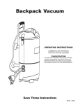
Installing The Cash Register
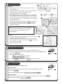
Install the cash register using the fixing
angle bracket provided with the register.
• Thoroughly clean the location where the
fixing angle bracket (B) is to be placed.
• Peel off the adhesive tape on the fixing
angle bracket.
• Hook the angle bracket onto the hook
(A) that is located at the bottom rear of
the register.
• Firmly stick the fixing angle bracket to
the table surface that you cleaned above.
To remove the register from the fixing
angle bracket.
• Lift up the front of the register and pull
the register towards you.
2
Important Notice
The cash register will
operate correctly only
after the following steps
have been carried out:
REG
OPX/Z
X1/Z1
X2/Z2
PGM
Mode Lock
Preparing The Cash Register
REG
OPX/Z
Initialising The Cash Register
PGM
To ensure the cash register operates correctly, initialize it using the following
procedure.
• Make sure the AC power cord is unplugged and batteries are not installed
in the register.
• Insert the manager (MA) key into the mode switch and turn to the REG position.
• Insert the plug of the AC power cord into the AC outlet. A buzzer will sound 3 times.
IMPORTANT: This operation must be performed without batteries installed.
• The register display should now show "
0.00".
NOTE: If the buzzer does not sound when the plug is inserted, the
initialization has not been done successfully. Wait at least one minute
after pulling out the plug, and insert the plug again.
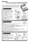
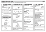
Installing the Batteries
Install three new R6 or LR6 batteries ("AA" size) according to the procedure
shown below with the power cord connected and set the mode switch to
REG position.
• Lift the rear of the printer cover and detach it.
• Open the battery compartment cover.
• Install three new R6 or LR6 batteries ("AA"size) as per the diagram.
When the batteries are properly installed " " on the display will disappear.
• Close the battery compartment cover.
MGR
MGR
X1/Z1
X2/Z2
Mode Lock
3
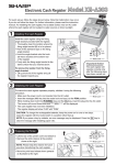
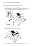
Install the Paper Roll
1.
Receipt
• Lift up the print roller release lever to unlock and open
the print roller arm.
• Set a paper roll in the paper roll cradle as per the diagram.
• Feed the end of the paper along with the paper
positioning guides as per the diagram.
• While holding down the paper, slowly close the print roller
arm, and push down the arm until you hear a click locking
the arm. Make sure you securely push down the center of
the wing part of the arm as per the diagram. The paper will
be fed automatically.
• Cut off the excess paper using the edge of the inner cover,
and replace the printer cover. Press the
key to make
sure the paper end comes out of the printer cover and
clean paper appears.
NOTE: If the print roller arm is not securely locked,
the printer will not work correctly. If this problem
occurs, open the arm, and close the arm as
instructed above.
2.
3.
4.
5.
Journal
• Insert the end of the paper into the slit of the spool. (Press the
key to feed more paper if required).
• Wind the paper two or three turns around the spool shaft.
• Set the spool on the bearing and press the
key to take up
excess slack in the paper.
• Replace the printer cover.
4
Changing The Printing Style
REG
OPX/Z
X1/Z1
The printer can either issue a customer receipt or provide a journal.
• Insert the manager (MA) key into the Mode Lock and turn to the PGM position.
• Press the #/TM/ST key.
• Enter 6 and press the
key.
1 1 0 0 0 1 1 1 for receipt or
0 1 0 0 0 1 1 1 for journal
• Press the #/TM/ST key followed by TL/NS to finalise operation.
5
MGR
X2/Z2
PGM
Mode Lock
Basic Programming
REG
OPX/Z
MGR
X1/Z1
Set the mode switch to the PGM position.
X2/Z2
Setting the Date
Enter the date in 8 digits using the day month-year (DD-MM-YYYY) format.
Then press #/TM/ST .
Example: Date (26 August, 2003) 2 6
0
PGM
Mode Lock
8 2 00 3 #/TM/ST
Setting the Time
Enter the time in 4 digits ("hhmm" format) using the 24 hour system. Then press #/TM/ST .
Example: Time (2:30pm) 1 4 2 0 #/TM/ST .
6
Entering A Basic Sale
REG
OPX/Z
MGR
X1/Z1
Insert the operator key into the mode lock and turn to the REG position.
X2/Z2
PGM
The cash register has thirty two department buttons in white through which to
Mode Lock
enter your sales. The purpose of these are to assist you in analysing your business.
(For example, department 1 could be used for food sales and department 2 for non food sales etc).
By allocating goods to the appropriate department buttons you are preparing and organising sales
data for the end of day reports.
• Insert the OP key and turn the mode lock to REG position ready for normal use.
• Enter the price of the goods without the decimal point then press one of the Department buttons.
• To enter another sale repeat as above by entering a price then a Department.
• Press #/TM/ST button to show the amount due.
• To calculate the change enter the money given by customer.
• For example £5.00 is entered as 5 00 .
• Press the payment key TL/NS . The amount of change due will be shown on the display.
7
Programming A Preset Price
REG
OPX/Z
MGR
X1/Z1
• Insert the manager (MA) key into the Mode Lock and turn to the PGM position
Procedure
X2/Z2
PGM
To program zero
Mode Lock
DEPTSHIFT*
Unit price
(max. six digits)
Dept. key
TL/NS
*To program departments 17 through 32, press the department shift key.
For department 33-50
Dept. code
DEPT#
To program zero
Unit price
(max. six digits)
#/TM/ST
TL/NS
To program another department, start from the beginning without pressing the TL/NS key.
For example to program department 1 as £10 preset.
• Ensure the Mode Lock is at PGM
• Enter 1 0 0 0 press 1 17 then TL/NS to finalise.
• Return to the REG position.
8
Programming A Department Name
REG
OPX/Z
MGR
X1/Z1
Insert the manager (MA) key into the Mode Lock and turn to the PGM position.
DEPTSHIFT
#/TM/ST
1
Press for 17
and above
X2/Z2
PGM
Dept. key
Mode Lock
12 Digit Name
For example to program department 1 as food.
• Ensure the Mode Lock is at PGM.
• Press the #/TM/ST key.
• Press 1 followed by
. Press 1 17
• Type in the 12 character name.
• Press the #/TM/ST key followed by TL/NS to finalise.
#/TM/ST
TL/NS
9
Programming A Receipt Message
REG
OPX/Z
MGR
X1/Z1
Insert the manager (MA) key into the Mode Lock and turn to the PGM position.
X2/Z2
PGM
#/TM/ST
4
Enter line
number
(1-3 as standard,
upto 6 lines optional).
24 character
message
#/TM/ST
TL/NS
Mode Lock
For example to program a message.
• Ensure the Mode Lock is at PGM.
• Press 4 followed by
.
• Press 1 (for line) followed by
.
• Type in your 24 character max. message and press #/TM/ST .
• Press 2 (for line 2) followed by
.
• Type in your 24 character max. message and press #/TM/ST .
• Press 3 (for line 3) followed by
.
• Type in your 24 character max. message and press #/TM/ST .
• Press TL/NS at any stage to finalise.
• Return to the REG position.
10 Reporting
The cash register has two reporting types. Use the reading function (X) when
you need to take a reading of sales information entered since the last reset.
This reading can be taken any number of times without clearing totals.
Use the resetting function (Z) when you need to clear the registers memory.
The reports can be taken in the X1/Z1 mode for daily sales or X2/Z2 for periodic
(monthly) reports. For further information please refer to the instruction manual.
REG
OPX/Z
MGR
X1/Z1
X2/Z2
PGM
Mode Lock
Example Daily Reports
• Insert the manager (MA) key and turn to X1/Z1.
• To read press TL/NS .
• To reset press
TL/NS .
• Return to REG position once the report has finished.
!
Common Solutions
1) The audit/journal take-up spool is not working. I: Please refer to Section 4 "Changing the Printing
Style - Journal Options".
2) Receipt feeding correctly but not printing. I: Ensure that you are using Thermal Paper. II: Ensure that
the paper has been installed into the printer correctly. Please see Section 3 for details.