1
Hotwire® TDM SHDSL Endpoints
Models 7995-A2-411, 7995-A2-421, 7995-A2-422,
7995-A2-700, 7996-A2-410, 7996-A2-420, and 7996-A2-700
Installation Instructions
Document Number 7990-A2-ZN10-30
December 2005
Contents
End User License Agreement (Zhone and Affiliates) ...............................................................
Product Documentation Online .................................................................................................
Package Checklist .....................................................................................................................
Installation Overview ................................................................................................................
Connecting Power to the Unit ...................................................................................................
Connecting to the Network .......................................................................................................
Connecting to a DTE .................................................................................................................
LEDs .........................................................................................................................................
Connecting to a System Terminal .............................................................................................
Asynchronous Terminal Interface Menu ...................................................................................
Entering Identity Information ...................................................................................................
Selecting a Configuration Method ............................................................................................
Configuring the Unit Using the Configuration Menus .............................................................
Displaying Configuration Options ............................................................................................
Configuration Edit/Display .......................................................................................................
Configuring the Unit Using the Internal Switches ....................................................................
Important Safety Instructions ....................................................................................................
CE Marking ...............................................................................................................................
Contacting Global Service and Support ....................................................................................
Technical Support ......................................................................................................................
Service Requirements ................................................................................................................
Trademarks ................................................................................................................................
7990-A2-ZN10-30
Hotwire TDM SHDSL Endpoints
2
3
4
4
5
6
6
7
8
9
10
10
10
11
11
25
29
29
30
30
30
30
1
End User License Agreement (Zhone
and Affiliates)
Do not install this Software unless you agree to these provisions.
Return the Software promptly for a refund if you do not agree.
License. Zhone Technologies, Inc. and/or an affiliate ("Zhone") hereby grants you
("User")—either an individual or a single business entity—the non-exclusive right to install,
access, run, or inter. act with ("Use") one copy of the enclosed software (which may have been,
or may be, provided on media, as part of a hardware platform, through download, or otherwise)
and associated documentation ("Software") on the first computer system on which User installs
the Software ("System") solely for internal business purposes (including, without limitation,
providing products and services to User's customers) and subject to the restrictions below).
Zhone may, in its sole discretion, make available future updates or upgrades to the Software each
of which is also Software subject hereto. Title to and all patent rights, copyrights and other
intellectual property rights in the Software are retained by Zhone and its direct and indirect
suppliers and licensors ("Licensors").
Restrictions. The Software may not be (a) Used on or from any system other than the System; (b)
Used with more than any maximum number of subscribers stated in the documentation
accompanying the Software; (c) Used so as to circumvent any technological measure included
therein or provided by Zhone from time to time to control access to or limit use of the Software;
(d) sublicensed, rented, leased or lent to third parties; (e) imported or exported into any
jurisdiction except in compliance with all applicable laws of the United States and such
jurisdiction; (f) transferred to a third party unless (A) User transfers the original and all surviving
copies to a third party who has agreed in writing to be bound hereby and (B) such third party pays
to Zhone such reasonable additional fee as Zhone may impose from time to time with respect to
such transfer; or (g) made available to third parties as part of any time-sharing or service bureau
arrangement. User shall not have the right to use the Software or any portion thereof for a use
other than that contemplated by its documentation. User will not copy all or any part of the
Software or attempt, or encourage or permit any third party, to modify, adapt, make derivative
works from, reverse engineer, reverse compile, disassemble or decompile the Software or any
portion thereof except and only to the extent that such activity is expressly permitted by law
notwithstanding this limitation. Violation of any of the foregoing shall be deemed a material
breach hereof. User may make a reasonable number of copies solely for archival or disaster
recovery and subject to the restrictions imposed by copyright law, but may not modify or
otherwise copy the Software. User agrees to reproduce product identification, copyright and
other proprietary notices of Zhone and Licensors on all copies. User's rights are only as expressly
stated herein. Zhone may immediately terminate your rights if you violate the provisions hereof.
Limited Warranty. Zhone warrants that the media containing the Software is free from defects in
material and workmanship for ninety (90) days following your purchase of the Software. You
may provide written notice of such defect (addressed to Zhone Technologies, Inc., Attention:
Customer Service, 7001 Oakport Street @ Zhone Way, Oakland, CA 94621) no later than ten
(10) days following expiration of such period and, as your sole and exclusive remedy, Zhone will
provide replacement media. NEITHER ZHONE NOR ITS LICENSORS MAKE ANY OTHER
WARRANTY, EXPRESS, IMPLIED OR STATUTORY. ZHONE AND ITS LICENSORS
2
Hotwire TDM SHDSL Endpoints
7990-A2-ZN10-30
DISCLAIM ALL WARRANTIES OF FITNESS FOR PARTICULAR PURPOSE,
MERCHANTABILITY AND NON-INFRINGEMENT. Some states or other jurisdictions do not
allow the exclusion of implied warranties on limitations on how long an implied warranty lasts,
so the above limitations may not apply to you. This warranty gives you specific legal rights, and
you may also have other rights which vary from one state or jurisdiction to another.
Limit of Liability. In case of any claim hereunder or related to the Software, neither Zhone nor its
Licensors shall be liable for direct damages exceeding the price paid by User for the Software or
for special, incidental, consequential or indirect damages, even if advised in advance of the
potential thereof.
U.S. Government Users. The Software is a "commercial item" as defined at 48 C.F.R. 2.101,
consisting of "commercial computer software" and "commercial computer software
documentation" as such terms are used in 48 C.F.R. 12.212. Under 48 C.F.R. 12.212 and 48
C.F.R. 227.7202-1 to 227.7202-4, U.S. Government Users acquire the Software only with the
rights set forth therein.
Third Party Licensors. This Zhone End User License Agreement may be accompanied by
differing or additional provisions applicable to portions of the Software provided by one or more
Licensors ("Licensor Provisions"). User acknowledges and agrees that its Use of such portions of
the Software is subject to the Licensor Provisions.
Product Documentation Online
Complete documentation for this product is available at www.zhone.com.
Select the following document:
Hotwire TDM SHDSL Endpoints, Models 7995-A2-411, 7995-A2-421, 7995-A2-422,
7995-A2-700, 7996-A2-410, 7996-A2-420 and 7996-A2-700, User’s Guide
7990-A2-ZN10-30
Hotwire TDM SHDSL Endpoints
3
Package Checklist
Verify that your package contains:
z
Hotwire® TDM SHDSL Endpoint
z
24 VDC power transformer with separate power cable
– or –
6-conductor direct connection DC power cable
z
8-position modular-to-8-position modular network cable
z
DB9-to-8-position modular terminal cable
For Model 7995, your package should also contain a:
z
V.35 cable adapter
Notify your sales representative if anything is missing or damaged.
Installation Overview
Installation and configuration of the Hotwire 799x endpoint consists of:
z
Connecting power to the unit.
z
Connecting to the network.
z
Connecting to a DTE.
z
Connecting a system terminal.
z
Providing initial unit identity information or changing existing identity information.
z
Configuring your unit using the Configuration Edit menus.
Before you install the unit, read the Important Safety Instructions on page 29.
See the Hotwire TDM SHDSL Endpoints, Models 7995-A2-411, 7995-A2-421, 7995-A2-422,
7995-A2-700, 7996-A2-410, 7996-A2-420 and 7996-A2-700, User’s Guide for additional
information about:
z
Configuration Options
z
Messages and Troubleshooting
z
Technical Specifications
z
Connectors, Cables, and Pin Assignments
4
Hotwire TDM SHDSL Endpoints
7990-A2-ZN10-30
Connecting Power to the Unit
If your package includes a power transformer:
1 Plug the power cable into an AC outlet having a nominal voltage rating between 100–240
VAC.
2 Connect the power cable to the transformer.
3 Connect the output cable of the transformer to the connector marked POWER on the rear
panel.
If your package includes a direct-connection DC power cable:
Connect the unit to an external +24 or –48 VDC SELV (Safety Extra Low Voltage) power source
as described in the following section.
Connecting the Unit to an Optional External +24 or
–48 VDC Power Source
Using the DC power cable, the unit is capable of operating on a +24 VDC or –48 VDC SELV
power supply.
To use the DC power cable for +24 VDC:
Procedure
1
2
3
4
5
Connect the green wire to a suitable ground.
Connect the orange wire to the +24 VDC source.
Connect the white wire to the return.
Cut the black, red, and blue wires off at the outer insulation.
Plug the power connector into the unit.
To use the DC power cable for –48 VDC:
Procedure
1
2
3
4
5
Connect the green wire to a suitable ground.
Connect the orange wire to the –48 VDC source.
Connect the black wire to the return.
Cut the red, white, and blue wires off at the outer insulation.
Plug the power connector into the unit.
7990-A2-ZN10-30
Hotwire TDM SHDSL Endpoints
5
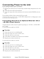
Power Cable Pinouts
Pin Number
Wire Color
Signal
1
Black
–48 VDC Return
2
Red
–48 VDC Return
3
Green
Ground
4
White
+24 VDC Return
5
Orange
+24 VDC/–48 VDC
6
Blue
No Connection
6
5
4
3
2
1
99-16291
Connecting to the Network
Procedure
To connect your unit to the network:
1 Connect one end of the supplied 8-position modular-to-8-position modular network cable
into the rear panel DSL jack.
2 Connect the other end to your DSL network interface.
NOTE:
Do not use a flat VF network cable as this may severely degrade the performance of the
unit. Use only Cat 5 twisted-pair network cable.
Connecting to a DTE
Model
DTE Connection
7995
The synchronous interface is a 25-pin EIA-530-A interface. Depending on the cable
used, the interface can be adapted to an X.21, RS-449, or V.35 interface. A V.35
cable may be used with the supplied adapter.
7996
The G.703 interface is either two BNC connectors (Transmit and Receive) for a
75-ohm unbalanced interface or an 8-position, unkeyed modular connector for a
120-ohm balanced interface.
See Connectors, Cables, and Pin Assignments in the User’s Guide for specifications of the
connectors and cables.
6
Hotwire TDM SHDSL Endpoints
7990-A2-ZN10-30
LEDs
®
TE
D
SL
D
PO
W
ER
AL
AR
M
TE
ST
TM
7995 TDM SHDSL
02-17143
The following table contains a description of the LEDs on the Hotwire 799x endpoint’s front
panel.
Label
Color
LED is . . .*
Indicating . . .
POWER
Green
On
Normal operation.
Off
No power to the unit.
Slow Cycling
Unit is in minimum mode and a download is
required.
On
Device failure, or self-test has failed.
Off
Self-test passed.
ALARM
TEST
DSL
DTE (7995)
G.703 (7996)
Red
Yellow
Green
Green
On
Loopback test in progress.
Off
No tests in progress.
Slow Cycling
Self-test in progress.
On
DSL link is up.
Off
The DSL link is down.
Slow Cycling
DSL training in progress.
On
DTE port is operational.
Off
DTE: No signal on port or configured DTR or RTS
are not active.
G.703: No signal on port.
Slow Cycling
G.703: Remote Alarm Indication received.
Fast Cycling
G.703: OOF, LOF, EER, or AIS condition
received.
* Slow Cycling: LED turns off and on in equal duration once per second.
Fast Cycling: LED turns off and on in equal duration 5 times per second.
7990-A2-ZN10-30
Hotwire TDM SHDSL Endpoints
7
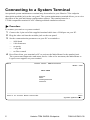
Connecting to a System Terminal
An optional system maintenance terminal may be attached to your Hotwire 799x endpoint
through the modular jack on the rear panel. The system maintenance terminal allows you to view
the status of the unit and change configuration options. The terminal must be a
VT100-compatible terminal or a PC running terminal emulation software.
Procedure
To connect your unit to a system terminal:
1 Connect the 9-pin end of the supplied terminal cable into a COM port on your PC.
2 Plug the other end into the modular jack on the rear panel.
3 Set the communication parameters on your PC or terminal to:
—
—
—
—
—
9600 baud
8 bit characters
no parity
1 stop bit
no flow control
4 Press Enter from your terminal or PC to activate the Main Menu for the attached unit.
The system runs diagnostics and status checks. After a few moments, the Main Menu or
Logon screen appears on your terminal.
main
Access Level: Administrator
Model 799x
MAIN MENU
Status
Test
Configuration
Control
----------------------------------------------------------------------------Ctrl-a to access these functions
Exit
System Operational
8
Hotwire TDM SHDSL Endpoints
7990-A2-ZN10-30
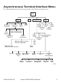
Asynchronous Terminal Interface Menu
The following illustration shows the menu paths to the different terminal screens.
Main
Status
Test
Configuration
Reset
Change Download
Device
Code
Identity
Apply
Administer
Download
Logins
System and Performance Display Identity
Test Status
Statistics
LEDs
7995: (Not Applicable)
DSL
7996: G.703 Statistics
Error
Statistics
Current
DSL
DSL
Performance
Performance
Statistics
Factory
Current Configuration
Config
Edit/Display
Configuration
Loader
Abort
All
Tests
7995: Sync Data Port Tests
7996: (Not Applicable)
Device
Tests
7995: DSL Tests
7996: DSL and G.703 Tests
DSL Port
Control
DSL Port
Threshold
Traps
7995: Sync Port
7996: G.703
System Communication Management
Options
Port
and
Communication
Telenet Communication General SNMP SNMP NMS SNMP
Session
Protocol
Management
Security
Traps
02-17046
7990-A2-ZN10-30
Hotwire TDM SHDSL Endpoints
9
Entering Identity Information
After accessing your unit for the first time, use the Change Identity screen to determine SNMP
administrative system information that will be displayed on the Identity screen of the Status
branch. To access the Identity screen, follow this menu selection sequence:
Main Menu → Control → Change Identity
Selecting a Configuration Method
You can make configuration changes either through a VT100-compatible terminal and the unit’s
Configuration menus or by manually changing switches on the board. The unit is shipped with
the switchpacks disabled to allow settings to be made through the Configuration menus. See the
User’s Guide for detailed information about the configuration options and switch settings.
Configuring the Unit Using the
Configuration Menus
Use the Configuration menu to select, display, or change configuration option settings.
NOTE:
The Hotwire 799x endpoint is shipped configured as an STU-R. If you use this unit as an
STU-R, the configuration options may not need to be altered.
The unit has two sets of configuration option settings:
z
The Current Configuration: The unit’s active set of configuration options.
z
The Default Factory Configuration: A read-only configuration area containing the factory
default configuration options.
10
Hotwire TDM SHDSL Endpoints
7990-A2-ZN10-30
Displaying Configuration Options
To display configuration options, you must first load a configuration into the edit area. To load a
configuration option set into the configuration edit area, follow this menu selection sequence:
Main Menu → Configuration (Load Configuration From)
Make a selection by placing the cursor at your choice and pressing Enter.
If you select . . .
Then . . .
Current
Configuration
The selected configuration option set is loaded and the Configuration
Edit/Display menu screen appears.
Configuration Loader
The Configuration Loader screen is displayed allowing you to upload
or download configurations from a TFTP server.
Default Factory
Configuration
The selected configuration option set is loaded and the Configuration
Edit/Display menu screen appears.
Configuration Edit/Display
The Configuration Edit/Display screen is displayed when the current or default configuration is
loaded. To access the Configuration Edit/Display screen, follow this menu selection sequence:
Main Menu → Configuration → Current Configuration
– or –
Main Menu → Configuration → Default Factory Configuration
main/config/edit
Model:799x
CONFIGURATION EDIT/DISPLAY
DSL Port
DSL Port Threshold Traps
SYNC Port | G.703
System Options
Communication Port
Management and Communication
----------------------------------------------------------------------------Ctrl-a to access these functions, ESC for previous menu
MainMenu
Exit
Save
7990-A2-ZN10-30
Hotwire TDM SHDSL Endpoints
11
Select . . .
To Access the . . .
To Configure the . . .
DSL Port
DSL Interface Options (Table 1)
DSL ports on the unit.
DSL Port
Threshold Traps
DSL Port Threshold Trap Options
(Table 2)
Threshold for DSL traps (for
the STU-C only).
SYNC Port
Synchronous Data Port Options – Model
7995 (Table 3)
Synchronous DTE interface
(Model 7995)
G.703
G.703 Interface Options – Model 7996
(Table 4)
G.703 interface
(Model 7996)
System Options
System Options (Table 5)
General system options of the
unit.
Communication
Port
Communication Port Options (Table 6)
Unit’s COM port options.
Management and
Communication
z
Telnet Session Options (Table 7)
z
Communication Protocol Options
(Table 8)
z
General SNMP Management Options
(Table 9)
z
SNMP NMS Security Options
(Table 10)
z
SNMP Traps Options (Table 11)
Management support of the
unit through SNMP and Telnet
(Telnet is for the STU-C only).
For complete details about the configuration options, see the Hotwire TDM SHDSL Endpoints,
Models 7995-A2-411, 7995-A2-421, 7995-A2-422, 7995-A2-700, 7996-A2-410, 7996-A2-420
and 7996-A2-700, User’s Guide.
Table 1:
DSL Interface Options (1 of 2)
Estimated Line Length
Possible Settings: Short, Medium, Long
Default Setting: Short
The estimated line length is the estimated distance from the local exchange to determine the
speeds that can be supported.
12
Hotwire TDM SHDSL Endpoints
7990-A2-ZN10-30
Table 1:
DSL Interface Options (2 of 2)
Start Up Margin
Possible Settings: 0dB – 15dB
Default Setting: 4dB
Specifies the Signal to Noise Ratio (SNR) margin a port must exceed to successfully train up
with the remote unit.
Max DSL Rate
Possible settings depend on whether Spectrum Management is enabled. Determines the
maximum speed of the DSL line when in Adaptive Rate mode (Max DSL Rate does not equal
Min DSL Rate).
Min DSL Rate
Possible settings depend on whether Spectrum Management is enabled. Determines the
minimum speed of the DSL line when in Adaptive Rate mode (Max DSL Rate does not equal
Min DSL Rate).
EIA-530 Payload Rate (for Model 7996 only)
Possible Settings: 64, 128
Default Setting: [Highest multiple of 64 kbps supported by the DSL Line Rate]
When the remote STU-R has an EIA-530-A interface, the Payload Rate set on the STU-C
determines the port speed of the synchronous port of the STU-R. Only 64 and 128 kbps are
selectable, otherwise this field is read-only.
Remotely Initiated Loopback
Possible Settings: Enable, Disable
Default Setting: Enable
Specifies whether the endpoint will respond to a loopback command from the access card.
Peer IP Address
Possible Settings: 001.000.000.000 – 223.255.255.255, Clear
Default Setting: 000.000.000.000
Specifies the peer IP address for the remote management link on the DSL loop.
Circuit Identifier
Possible Settings: ASCII text field, Clear
Default Setting: [blank]
Uniquely identifies the circuit number of the transmission vendor’s DSL line for
troubleshooting purposes.
7990-A2-ZN10-30
Hotwire TDM SHDSL Endpoints
13
Table 2:
DSL Port Threshold Trap Options
ES Trap Threshold
Possible Settings: 1–900, or 0 to Disable
Default Setting: 120
Specifies the threshold for Error Seconds events in a 15-minute interval after which a trap will
be sent.
SES Trap Threshold
Possible Settings: 1–900, or 0 to Disable
Default Setting: 15
Specifies the threshold for Severely Error Seconds events in a 15-minute interval after which a
trap will be sent.
UAS Trap Threshold
Possible Settings: 1–900, or 0 to Disable
Default Setting: 0
Specifies the threshold for Unavailable Seconds events in a 15-minute interval after which a
trap will be sent.
LOSW Trap Threshold
Possible Settings: 1–900, or 0 to Disable
Default Setting: 0
Specifies the threshold for Loss of Sync Word Seconds events in a 15-minute interval after
which a trap will be sent.
CRC Trap Threshold
Possible Settings: 1–900, or 0 to Disable
Default Setting: 0
Specifies the threshold for CRC events in a 15-minute interval after which a trap will be sent.
Attenuation Trap Threshold
Possible Settings: 1–127 dB, or 0 to Disable
Default Setting: 0
Specifies the threshold for loop attenuation in a 15-minute interval after which a trap will be
sent.
Margin Trap Threshold
Possible Settings: 1–15 dB, or 0 to Disable
Default Setting: 4
Specifies the threshold for the Signal-to-Noise ratio margin in a 15-minute interval after which
a trap will be sent.
14
Hotwire TDM SHDSL Endpoints
7990-A2-ZN10-30
Table 3:
Synchronous Data Port Options – Model 7995 (1 of 2)
Port Type
Possible Settings: E530A, V.35, RS449, X.21
Default Setting: E530A
Determines the port type for the data port.
Payload Rate
Possible Settings: 64 – 2304 kbps in 64k increments
Default Setting: 192 kbps
Specifies the payload rate of the port. This option is not displayed on the unit when Adaptive
Rate is enabled. The STU-C configures the payload rate for the STU-R when Adaptive Rate is
disabled (Max DSL Rate = Min DSL Rate, see Table 1, DSL Interface Options).
Transmit Clock Source
Possible Settings: Internal, External
Default Setting: Internal
Specifies whether the transmitted data for the synchronous data port is clocked using an
internal clock provided by the DCE or an external clock provided by the DTE connected to the
synchronous data port.
Invert Transmit Clock
Possible Settings: Disable, Enable
Default Setting: Disable
When configured as the STU-C and Transmit Clock Source is set to External, specifies
whether the clock supplied by the the unit on the TXC interchange circuit DB (ITU-T 114) is
phase inverted with respect to the Transmitted Data interchange circuit BA (ITU-T 103). This
configuration option is useful when an excessive cable length between the unit and the DTE
causes errors.
Send All Ones on Data Port Not Ready
Possible Settings: Both, Disable, DTR, RTS
Default Setting: Both
Specifies the conditions on the data port that determine when valid data is not being sent from
the DTE. When this condition is detected, all ones are sent to the network.
Action on Network LOS Alarm
Possible Settings: Halt, None
Default Setting: Halt
Specifies the action taken on the synchronous data port when an LOS (Loss Of Signal) alarm
is received on the DSL interface.
7990-A2-ZN10-30
Hotwire TDM SHDSL Endpoints
15
Table 3:
Synchronous Data Port Options – Model 7995 (2 of 2)
Network Initiated Data Channel Loopback
Possible Settings: Disable, Enable
Default Setting: Disable
Allows the initiation and termination of a Data Channel Loopback (DCLB) by the receipt of a
DCLB-actuate sequence or DCLB-release sequence from the network or far-end device.
Port (DTE) Initiated Loopbacks
Possible Settings: Disable, DTLB, DCLB, Both
Default Setting: Disable
Allows the initiation and termination of a local Data Terminal Loopback (DTLB) or remote
Data Channel Loopback (DCLB) by the DTE connected to this port. (DTLB is equivalent to a
V.54 loop 3, and DCLB is equivalent to a V.54 loop 2.) Control of these loopbacks is through
the DTE interchange circuits as specified by the V.54 standard.
Elastic Store
Possible Settings: Disable, Enable
Default Setting: Enable
When configured as the STU-C and Transmit Clock Source is set to External, used to enable or
disable a first-in, first-out (FIFO) buffer circuit for the incoming external clock. This circuit is
used to compensate for the differences between the frequencies of the data clocks for the two
units in the circuit. Do not enable Elastic Store if the attached DCE has an elastic store buffer
larger than 32 bits.
Table 4:
G.703 Interface Options – Model 7996 (1 of 2)
Framing
Possible Settings: Framed, Unframed
Default Setting: Framed
Specifies whether G.704 framing is used for the G.703 interface.
Line Coding
Possible Settings: AMI, HDB3
Default Setting: HDB3
Specifies the line coding format to be used by the G.703 interface.
Line Framing
Possible Settings: CRC4, noCRC4
Default Setting: noCRC4
Specifies the framing format to be used by the G.703 interface.
16
Hotwire TDM SHDSL Endpoints
7990-A2-ZN10-30
Table 4:
G.703 Interface Options – Model 7996 (2 of 2)
Time Slot 16
Possible Settings: Signaling, Data
Default Setting: Signaling
Specifies whether the G.703 interface is used for voice or data.
Send (AIS) on Network Failure
Possible Settings: Enable, Disable
Default Setting: Enable
Specifies the action taken on the signal transmitted to the G.703 when a valid signal cannot be
recovered from the network interface (LOS or OOF).
Primary Clock Source
Possible Settings: G.703, Internal
Default Setting: Internal
Specifies from where the unit will derive its timing.
Table 5:
System Options (1 of 2)
DSL Mode
Possible Settings: STU-C, STU-R
Default Setting: STU-R
Controls whether the unit is configured as a SHDSL Transceiver Unit – Central Site (STU-C)
or a SHDSL Transceiver Unit – Remote Terminal Site (STU-R).
NOTE: Changing this option will reset the unit.
Test Timeout
Possible Settings: Enable, Disable
Default Setting: Enable
Allows tests to end automatically. The feature should be enabled when the unit is remotely
managed so that control can be regained after a test is accidentally executed.
Test Duration (min)
Possible Settings: 1 – 120
Default Setting: 10
Number of minutes for a test to be active before automatically ending.
7990-A2-ZN10-30
Hotwire TDM SHDSL Endpoints
17
Table 5:
System Options (2 of 2)
G.703 Line Termination
(Model 7996)
Possible Settings: 75 ohms, 120 ohms
Default Setting: 120 ohms
Sets the line impedance for the unit.
Region Setting
Possible Setting: Annex B (read-only)
For an STU-C, specifies the set of unique, regional SHDSL operations parameters to be used
by the unit. Annex B is for European networks.
Spectrum Management
Possible Settings: Enable, Disable
Default Setting: Disable
For an STU-C, enabling spectrum management limits the DSL speeds on the unit to meet BT
Access Network Spectrum standards.
Country Code
Possible Setting: UK (read-only)
For an STU-C, determines the spectrum management standard to be used (ANFP for UK) to
calculate the speeds allowed on this unit which comply with spectrum management.
Table 6:
Communication Port Options (1 of 3)
Port Use
Possible Settings: Terminal, Net Link
Default Setting: Terminal
Specifies how the communications port is to be used.
Port Type
Possible Settings: Asynchronous, Synchronous
Default Setting: Asynchronous
Determines whether the communication port will be asynchronous or synchronous when Port
Use is set to Net Link.
18
Hotwire TDM SHDSL Endpoints
7990-A2-ZN10-30
Table 6:
Communication Port Options (2 of 3)
Data Rate
Possible Settings: 9.6, 14.4, 19.2, 28.8, 38.4, 57.6, 115.2
Default Setting: 9.6
Specifies the communication port baud rate.
Character Length
Possible Settings: 7, 8
Default Setting: 8
Determines the character length of the communication port.
Parity
Possible Settings: None, Odd, Even
Default Setting: None
Specifies the parity of the communication port.
Stop Bits
Possible Settings: 1, 1.5, 2
Default Setting: 1
Specifies the number of stop bits for the communication port.
Ignore Control Leads
Possible Settings: Disable, DTR
Default Setting: Disable
Specifies whether DTR is used.
Login Required
Possible Settings: Enable, Disable
Default Setting: Disable
Specifies whether an ID and password are required to access the asynchronous terminal
interface on the communication port when Port Use is set to Terminal. Login IDs are created
with a password and access level.
Port Access Level
Possible Settings: Administrator, Operator
Default Setting: Administrator
Specifies the highest level of access allowed when accessing an ATI session through a Telnet
session when Port Use is set to Terminal.
7990-A2-ZN10-30
Hotwire TDM SHDSL Endpoints
19
Table 6:
Communication Port Options (3 of 3)
Inactivity Timeout
Possible Settings: Enable, Disable
Default Setting: Disable
Provides automatic logoff of a Telnet session when Port Use is set to Terminal.
Disconnect Time (Minutes)
Possible Settings: 1 – 60
Default Setting: 5
Number of minutes of inactivity before the session terminates automatically when Port Use is
set to Terminal and Inactivity Timeout is enabled. Timeout is based on no keyboard activity.
Table 7:
Telnet Session Options (1 of 2)
Telnet Session
Possible Settings: Enable, Disable
Default Setting: Enable
Specifies if the unit will respond to a Telnet session request from a Telnet client on an
interconnected IP network.
Telnet Login Required
Possible Settings: Enable, Disable
Default Setting: Disable
Specifies whether a user ID and password are required to access to the ATI through a Telnet
session. Login IDs are created with a password and access level.
Session Access Level
Possible Settings: Administrator, Operator
Default Setting: Administrator
The Telnet session access level is interrelated with the access level of the Login ID.
Inactivity Timeout
Possible Settings: Enable, Disable
Default Setting: Disable
Provides automatic logoff of a Telnet session.
20
Hotwire TDM SHDSL Endpoints
7990-A2-ZN10-30
Table 7:
Telnet Session Options (2 of 2)
Disconnect Time (Minutes)
Possible Settings: 1 – 60
Default Setting: 5
Number of minutes of user inactivity before a Telnet session terminates automatically. Time
out is based on no keyboard activity.
Table 8:
Communication Protocol Options
Node IP Address
Possible Settings: 001.000.000.000 – 223.255.255.255, Clear
Default Setting: 000.000.000.000
For an STU-C, specifies the Node IP address.
Node Subnet Mask
Possible Settings: 000.000.000.000 – 255.255.255.255, Clear
Default Setting: 000.000.000.000
For an STU-C, specifies the Node Subnet Mask.
Default Network Destination
Possible Settings: None, COM, DSL
Default Setting: None
Specifies where the default management network is connected when Port Use is set to NetLink
for the COM port.. For example, if your default network is connected to the COM port, select
COM as the default management network destination.
Communication Port IP Address
Possible Settings: 001.000.000.000 – 223.255.255.255, Clear
Default Setting: Clear (000.000.000.000)
Specifies the Communication Port IP Address when Port Use is set to NetLink for the COM
port.
Communication Port Subnet Mask
Possible Settings: 001.000.000.000 – 255.255.255.255, Clear
Default Setting: Clear (000.000.000.000)
Specifies the Communication Port Subnet Mask when Port Use is set to NetLink for the COM
port.
7990-A2-ZN10-30
Hotwire TDM SHDSL Endpoints
21
Table 8:
Communication Protocol Options
Communication Port Link Protocol
Possible Settings: PPP, SLIP
Default Setting: PPP
Specifies the Communication Port link layer protocol when Port Use is set to NetLink for the
COM port.
Table 9:
General SNMP Management Options
SNMP Management
Possible Settings: Enable, Disable
Default Setting: Enable
Enables or disables the SNMP management features.
Community Name 1
Possible Settings: ASCII text field, Public, Clear
Default Text: Public
Identifies the name of the community allowed to access the unit’s MIB. The community name
must be supplied by an external SNMP manager when that manager attempts to access an
object in the MIB.
Name 1 Access
Possible Settings: Read, Read/Write
Default Setting: Read/Write
Determines the access level for Community Name 1.
Community Name 2
Possible Settings: ASCII text field, Clear
Default Text: Clear (null string)
Identifies the name of the second community allowed to access the unit’s MIB. The
community name must be supplied by an external SNMP manager when that manager
attempts to access an object in the MIB.
Name 2 Access
Possible Settings: Read, Read/Write
Default Setting: Read
Determines the access level for Community Name 2.
22
Hotwire TDM SHDSL Endpoints
7990-A2-ZN10-30
Table 10:
SNMP NMS Security Options
NMS IP Validation
Possible Settings: Enable, Disable
Default Setting: Disable
For IP Complex systems, specifies whether security checking is performed on the IP address
of SNMP management systems attempting to access the node.
NMS n IP Address
Possible Settings: 001.000.000.000 – 223.255.255.255, Clear
Default Setting: 000.000.000.000
For IP Complex systems, specifies the Internet Protocol address used to identify each SNMP
trap manager (limit of 10).
Access Type
Possible Settings: Read, Read/Write
Default Setting: Read
For IP Complex systems, determines the access level allowed for an authorized NMS when IP
address validation is being performed.
Table 11:
SNMP Traps Options (1 of 2)
SNMP Traps
Possible Settings: Enable, Disable
Default Setting: Enable
Controls the generation of SNMP trap messages.
NMS n IP Address
Possible Settings: 001.000.000.000 – 223.255.255.255, Clear
Default Setting: 000.000.000.000
For IP Complex systems, specifies the Internet Protocol address used to identify each SNMP
trap manager (limit of 5).
NMS n Destination
Possible Settings: DSL, COM
Default Setting: DSL
For IP Complex systems, provides the network destination path of each trap manager. COM
displays if Port Use is set to NetLink.
7990-A2-ZN10-30
Hotwire TDM SHDSL Endpoints
23
Table 11:
SNMP Traps Options (2 of 2)
General Traps
Possible Settings: Disable, Warm, AuthFail, Both
Default Setting: Both
Determines which SNMP traps are sent to each trap manager.
Enterprise Specific Traps
Possible Settings: Enable, Disable
Default Setting: Disable
Determines if SNMP traps are generated for enterprise-specific events.
Link Traps
Possible Settings: Disable, Up, Down, Both
Default Setting: Both
Determines if SNMP traps are generated for link up and link down for one of the
communication interfaces.
Link Traps Interfaces
Possible Settings:
7995: Network, SYNC, All
7996: Network, G.703, All
Default Setting: All
Determines if the SNMP linkUp, linkDown, and interface-related enterpriseSpecific traps are
generated for the network interface, synchronous or G.703 port, or both.
24
Hotwire TDM SHDSL Endpoints
7990-A2-ZN10-30
Configuring the Unit Using the Internal
Switches
You can use the internal switches to manually configure the unit.
! HANDLING PRECAUTIONS FOR STATIC-SENSITIVE DEVICES
This product is designed to protect sensitive components
from damage due to electrostatic discharge (ESD) during
normal operation. When performing installation
procedures, however, take proper static control precautions to
prevent damage to equipment. If you are not sure of the
proper static control precautions, contact your nearest
sales or service representative.
Procedure
To configure the unit using internal Switchpack S3:
1 Power off the unit.
2 Remove the enclosure cover:
—
—
Use a Phillips screwdriver to remove the two screws from the top of the unit.
Push a flat-blade screwdriver through the slots on both sides of the housing to free the
four inner latches.
3 Locate Switchpack S3 on the circuit board using Figure 1, Hotwire TDM SHDSL Endpoint
Switchpack Locations.
4 Set Switch 6 on Switchpack S3 to ON to enable the switchpack.
5 Set the switches to your desired configuration:
—
—
For Model 7995, refer to Table 12.
For Model 7996, refer to Table 13.
6 Replace the cover and fasten it with the two screws.
7 Power on the board to reset the unit and enable the new configuration.
7990-A2-ZN10-30
Hotwire TDM SHDSL Endpoints
25
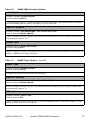
Switchpack Location
Use the following illustration to locate Switchpack S3.
Rear
Switchpack
S3
8
7
6 5
4
3
2
1
8
S3
7
6 5
4
3
2
1
ON
ON
Front
03-17364
Figure 1: Hotwire TDM SHDSL Endpoint Switchpack Locations
26
Hotwire TDM SHDSL Endpoints
7990-A2-ZN10-30
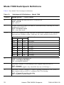
Model 7995 Switchpack Definitions
Table 12 lists Model 7995 Switchpack definitions.
Table 12:
Switchpack S3 Definitions – Model 7995
Switch #
Allows you to . . . Default in Bold
1
Control whether the unit is an STC-C or an STU-R
OFF = STU-R
ON = STU-C
2
Control enabling of either Fixed Rate or Auto Rate mode.
OFF = Fixed Rate Mode
ON = Auto Rate Mode
3, 4, 5
Select one of eight preset DSL line rates. If Auto Rate is enabled, DSL Line Rate
represents the Auto Rate ceiling. Valid only for a unit configured as an STU-C.
Switch Position
5
6
4
DSL Line Rate
Default in Bold
3
OFF
OFF
OFF
2056 kbps
OFF
OFF
ON
200 kbps
OFF
ON
OFF
264 kbps
OFF
ON
ON
392 kbps
ON
OFF
OFF
520 kbps
ON
OFF
ON
776 kbps
ON
ON
OFF
1032 kbps
ON
ON
ON
1544 kbps
Enable or disable Switchpack S3.
OFF = Switchpack Disabled
ON = Switchpack Enabled
7, 8
Control the sync port data rate. Specifies the maximum payload rate when the
DSL line rate is 200 kbps. Valid only for a unit configured as an STU-C, in Fixed
Rate Mode.
Switch Position
Sync Data Port Rate
7
8
OFF
OFF
192 kbps
OFF
ON
128 kbps
ON
ON
64 kbps
7990-A2-ZN10-30
Hotwire TDM SHDSL Endpoints
Default in Bold
27
Model 7996 Switchpack Definitions
Table 13 lists Model 7996 Switchpack definitions.
Table 13:
Switchpack S3 Definitions – Model 7996
Switch #
Allows you to . . . Default in Bold
1
Control whether the unit is an STU-C or an STU-R.
OFF = STU-R
ON = STU-C
2
Control enabling of either Fixed Rate or Auto Rate mode. Valid only for a unit
configured as an STU-C.
OFF = Fixed Rate mode
ON = Auto Rate mode
3, 4, 5
Select one of eight preset DSL line rates. If Auto Rate is enabled, DSL Line Rate
represents the AutoRate ceiling. Valid only for a unit configured as an STU-C.
Switch Position
6
DSL Line Rate
5
4
3
OFF
OFF
OFF
2056 kbps
OFF
OFF
ON
200 kbps
OFF
ON
OFF
264 kbps
OFF
ON
ON
392 kbps
ON
OFF
OFF
520 kbps
ON
OFF
ON
776 kbps
ON
ON
OFF
1032 kbps
ON
ON
ON
1544 kbps
Default in Bold
Enable or disable Switchpack S3.
OFF = Switchpack Disabled
ON = Switchpack Enabled
7
Determines whether G.704 Framing is used. Applies only to an STU-C.
OFF = Framed
ON = Unframed (Applies only when DSL line rate is 2056 kbps.)
8
Determines whether Channel 16 contains signaling information (voice mode) or
data. Applies only to an STU-C configured for G.704 framing.
OFF = Channel 16 used for signaling
ON = Channel 16 used for data
28
Hotwire TDM SHDSL Endpoints
7990-A2-ZN10-30
!
Important Safety Instructions
1 Read and follow all warning notices and instructions marked on the product or included in
the manual.
2 Input power to this product must be provided by one of the following: (1) a UL Listed/CSA
Certified power source with a Class 2 or Limited Power Source (LPS) output for use in
North America; or (2) a 24 or –48 VDC National Electric Code (NEC) ANSI/NFPA
70/Canadian Electric Code (CEC) Class 2 circuit installed in accordance with articles
110-16, 110-17, and 110-18 of the NEC, and articles 2-308, 2-310, 2-312, 2-314, 2-200, and
2-202 of the CEC, or (3) a Safety Extra Low Voltage (SELV) power source with a maximum
available output of less than 240 VA, certified for use in the country of installation.
3 Slots and openings in the cabinet are provided for ventilation. To ensure reliable operation
of the product and to protect it from overheating, these slots and openings must not be
blocked or covered.
4 Do not allow anything to rest on the power cord and do not locate the product where persons
will walk on the power cord.
5 Do not attempt to install or service this product yourself, as opening or removing covers
may expose you to dangerous high voltage points or other risks. Refer all installation and
servicing to qualified service personnel.
6 General purpose cables are provided with this product. Special cables, which may be
required by the regulatory inspection authority for the installation site, are the responsibility
of the customer.
7 When installed in the final configuration, the product must comply with the applicable
Safety Standards and regulatory requirements of the country in which it is installed. If
necessary, consult with the appropriate regulatory agencies and inspection authorities to
ensure compliance.
8 A rare phenomenon can create a voltage potential between the earth grounds of two or more
buildings. If products installed in separate buildings are interconnected, the voltage
potential may cause a hazardous condition. Consult a qualified electrical consultant to
determine whether or not this phenomenon exists and, if necessary, implement corrective
action prior to interconnecting the products.
9 In addition, if the equipment is to be used with telecommunications circuits, take the
following precautions:
— Never install telephone wiring during a lightning storm.
— Never install telephone jacks in wet locations unless the jack is specifically designed
for wet locations.
— Never touch uninsulated telephone wires or terminals unless the telephone line has
been disconnected at the network interface.
— Use caution when installing or modifying telephone lines.
— Avoid using a telephone (other than a cordless type) during an electrical storm. There
may be a remote risk of electric shock from lightning.
— Do not use the telephone to report a gas leak in the vicinity of the leak.
CE Marking
When the product is marked with the CE mark on the equipment label, a supporting Declaration
of Conformity may be downloaded from the Zhone website at www.zhone.com.
7990-A2-ZN10-30
Hotwire TDM SHDSL Endpoints
29
Contacting Global Service and Support
Contact Global Service and Support (GSS) if you have any questions about this or other Zhone
products. Before contacting GSS, make sure you have the following information:
z
Zhone product you are using
z
System configuration
z
Software version running on the system
z
Description of the issue
Technical Support
If you require assistance with the installation or operation of your product, or if you want to
return a product for repair under warranty, contact GSS. The contact information is as follows:
E-mail
support@zhone.com
Telephone (North America)
877-ZHONE20
Telephone (International)
510-777-7133
Internet
www.zhone.com/support
If you purchased the product from an authorized dealer, distributor, Value Added Reseller (VAR),
or third party, contact that supplier for technical assistance and warranty support.
Service Requirements
If the product malfunctions, all repairs must be performed by the manufacturer or a
Zhone-authorized agent. It is the responsibility of users requiring service to report the need for
service to GSS.
Trademarks
Acculink, ADSL/R, Bitstorm, Comsphere, DSL the Easy Way, Etherloop, FrameSaver, GigMux,
GranDSLAM, GrandVIEW, Hotwire, the Hotwire logo, iMarc, JetFusion, Jetstream, JetVision,
MALC, NextEDGE, Net to Net Technologies, Paradyne, the Paradyne logo, Quick Channel,
Raptor, ReachDSL, SLMS, StormPort, TruePut, Z-Edge, Zhone, ZMS, and the Zhone logo are
trademarks owned by Zhone Technologies, Inc., which may be registered in some jurisdictions.
Copyright © 2005 Zhone Technologies, Inc.
30
Hotwire TDM SHDSL Endpoints
7990-A2-ZN10-30
7990-A2-ZN10-30
Hotwire TDM SHDSL Endpoints
31
*7990-A2-ZN10-30*
*7990-A2-ZN10-30*