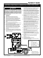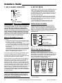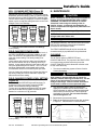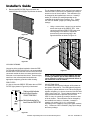
1
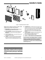
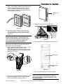
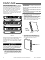
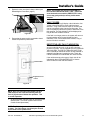
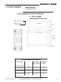
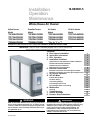
Installation
Operation
Maintenance
18-HE53D1-5
Whole House Air Cleaner
Upflow Furnace
Models
Downflow Furnace
Models
Air Handler
Models
50 Hz Air Handler
Models
*FD145ALFR000B
*FD175ALFR000B
*FD210ALFR000B
*FD245ALFR000B
*FD14DALFR000B
*FD17DALFR000B
*FD21DALFR000B
*FD24DALFR000B
*FD215ALAH000B
*FD235ALAH000B
*FD260ALAH000B
* May be "A" or "T"
TFD215ALAH005B
TFD235ALAH005B
TFD260ALAH005B
ALL phases of this installation must comply with NATIONAL, STATE AND LOCAL CODES
IMPORTANT — This Document is customer property and is to remain with this unit.
Please return to service information pack upon completion of work.
Contents
A.
B.
C.
D.
Duct Support Installation
Application Information
Door Operation
Installation Guidelines
Upflow Furnace and Upflow Air Handler Installation
Downflow Air Handler Installation
Downflow Furnace Installation
Side Return Furnace Installation
E. Electrical Connections
Electrical Connections to a Comm Sys Air Handler
Electrical Connections toa Comm Sys 3-Stage Furnace
F. Air Cleaner Operation
G. SET-UP Mode
Installer Set-Up Mode
Pre-Filter Setting
Cell Cleaning Setting
Field Charger Power Level
Field Charger Power Level Setting
H. Maintenance
Cleaning
I. Troubleshooting
J. Outline Drawings
K. Pressure Drop Information
! WARNING
▲
RISK OF ELECTRIC SHOCK: These servicing instructions
are for use by qualified personnel only. To reduce the risk
of electric shock, do not perform any servicing other than
that contained in these operating instructions unless you
are qualified to do so.
© Trane 2007
! WARNING
▲
This information is for use by individuals having adequate
backgrounds of electrical and mechanical experience. Any
attempt to repair a central air conditioning product may
result in personal injury and/or property damage. The
manufacturer or seller cannot be responsible for the
interpretation of this information, nor can it assume any
liability in connection with its use.
4
5
6
6
6
6
7
8
9
10
11
12
12
12
12
13
13
13
13
13
18
19
22
Installer’s Guide
2
Numbers in [brackets] are for 50 Hz international systems.
Pub. No. 18-HE53D1-5
Installer’s Guide
4
3
5
6
8
2
12 3
7
1
Figure 1 Components of the Air Cleaner
Unpack the Air Cleaner and check to make sure all
components are included. They consist of:
1) PRE-FILTER - traps large particles such as hair and
lint before they can enter the cell section.
2) FIELD CHARGER - Charges the contaminants. Only
to be removed, cleaned or serviced by a qualified
technician.
3) COLLECTION CELL (2) - removes and collects very
small impurities from the air.
4) CABINET - mounts between the furnace/air handler
and return air duct work and houses the COLLECTION CELLS, FIELD CHARGER and PRE-FILTER.
5) POWER DOOR - the solid state power supply components that convert the 24 Volt AC to the high-voltage,
direct current required to power the FIELD CHARGER
and COLLECTION CELLS. Allows access to the
COLLECTION CELLS, FIELD CHARGER and PREFILTER.
6) TRANSFORMER - supplies 24 Volts to the indoor unit
and air cleaner (not included with 50 Hz units)
7) 24 VOLT POWER/CONTROL CABLE
8) GASKET, LITERATURE AND HARDWARE PACKET
Check carefully for any shipping damage. This must be
reported to and claims made against the transportation
company immediately. Check to be sure all major
components are in the unit. Any missing parts should
be reported to your supplier at once, and replaced with
authorized parts only.
NOTE: International (50 Hz) Timings:
Due to differences in electrical systems outside the
United States, customers with 50 Hz electrical
systems will need to be aware of minor differences
in the timings shown in this guide. 50 Hz timings
will appear in [brackets] following the standard 60 hz
timings.
Pub. No. 18-HE53D1-5
Numbers in [brackets] are for 50 Hz international systems.
3
Installer’s Guide
A. DUCT SUPPORT INSTALLATION
Step 1: Review the figures below and determine which one looks like your application.
Step 2: To prevent racking of the air cleaner, support duct per the illustration.
Joist or Rafter
Furnace
or
air handler
Air Cleaner
Air cleaner cabinet
must align with
furnace or air handler
cabinet to prevent air
cleaner cabinet deflection
Supply
Furnace
ONLY
Return
Air
R/A Duct
Coil
Air
Cleaner
Figure 2
Supply
Plenum
Figure 3
Rafter or Joist
Air
Return
Cleaner Plenum
Furnace or
Air Handler
Joist or Flooring
Return Air Plenum must
be supported from building
structure to prevent air cleaner
cabinet deflection
Supply
Plenum
Furnace or
Air Handler
Return
Air
Cleaner Plenum
Return Air Plenum must be
supported from building structure
to prevent air cleaner cabinet deflection
Figure 4
4
Return Air Duct must
be supported from
building structure to
prevent air cleaner
cabinet deflection.
Use either a support
from the ceiling or
support from the floor.
Figure 5
Numbers in [brackets] are for 50 Hz international systems.
Pub. No. 18-HE53D1-5
Installer’s Guide
B. APPLICATION INFORMATION
NOTE: Do NOT install the air filter in the discharge air
stream of either the air handler or furnace.
Airflow
Airflow
Airflow
Bottom Return
(Furnace / Air Handler)
Left or Right Side Mounting
(Furnace ONLY)
Top Return
(Furnace / Air Handler)
Figure 6 Mounting Location of Air Cleaner
Airflow
Direction Arrow
! CAUTION
▲
Do NOT install air cleaner where the filter can be
exposed to UV light. UV light can cause the plastic
material to deteriorate, which may lead to filter damage.
This air cleaner cabinet must be mounted in the return air
duct of a central forced-air Furnace/Air Handler.
Select a location that meets the following:
1. The face of the cell must be at a right angle to the air
stream.
2. Allow a minimum of 28 inches clearance in front of the
air cleaner to permit removal of cells and Pre-Filter.
3. Flow-through Bypass Humidifiers
Excessive bypass air may cause water blow-off, which
will adversely affect system operation and air cleaner
performance. To verify bypass airflow, follow the
Bypass Humidifier Pre-Installation Checkout and SetUp Procedures available through your local distributor.
Ask for publication number 18-CH37D1-1.
Figure 7 Airflow Direction
5. The PRE-FILTER must be on the entering airstream
side of the air cleaner cabinet. The mounting flange on
this side of the cabinet has the single row of holes for
attaching ductwork.
6. On side return furnace applications, the air cleaner
may be installed on either side of the cabinet.
Position the PRE-FILTER on the side away from the
furnace. The COLLECTION CELL guide key, installed
in the cabinet will only allow the cells to be installed in
the proper direction. Airflow direction must agree with
airflow arrows on the cabinet.
7. It is recommended that sheet metal turning vanes be
installed inside an elbow on ductwork attached to the
entering airstream side of the air cleaner. This improves
the air distribution over the COLLECTION CELLS. See
Figure 8.
Air Cleaner
Cabinet
Steam and Flow-through Fan Power Duct-mounted
Humidifiers
Follow the Humidifier installation instructions. These
should only be installed on the supply air side of the
system.
Other Duct Mounted Humidifiers
Not recommended for installation with the air cleaner.
Airflow
Turning
Vanes
4. Install the air cleaner such that the airflow direction
arrow on the cabinet always points towards the furnace/ air handler. See Figure 7.
! WARNING
▲
Hazardous Voltage!
Disconnect all electric power, including remote
disconnects before servicing. Follow proper lockout/
tagout procedures to ensure the power can not be
inadvertently energized. Failure to disconnect power
before servicing could result in death or serious injury.
Pub. No. 18-HE53D1-5
Figure 8 Turning Vanes
Numbers in [brackets] are for 50 Hz international systems.
5
Installer’s Guide
8. Use transition fittings where return air duct dimensions
do not match the air cleaners opening dimensions.
Gradual transitions are preferred for greatest efficiency.
Four inches per linear foot (approximately 20° angle)
should be allowed, space permitting.
9. Seal all joints in the return air system to prevent dust
from entering the air stream.
Step 2: Insert tabs into cabinet slots. Edge of door
should fit into channel against gasket (see detail). See
Figure 12.
Gasket
NOTE: Do NOT use a silicon based sealant. This
causes a coating on the FIELD CHARGER pins that will
decrease the efficiency of the air cleaner.
C. DOOR OPERATION
The air cleaner comes with the Power Door installed on the
unit. The Power Door and the internal components will
need to be removed before installation. Follow these
guidelines for removing and re-installing the door:
REMOVING THE POWER DOOR:
Figure 12
Step 3: Rotate door to closed position. Ensure ends of
door overlap the cabinet (see detail). See Figure 13.
Step 1: To remove the door, hold handles and rotate
latches as shown in Figure 9.
Rotate Latches
Cabinet Edge
Figure 13
Figure 9
Step 2: Rotate the door to fully remove from the air
cleaner. See Figure 10.
Step 4: Rotate latches to secure door as shown in Figure
14.
Rotate door away from unit to remove
Air Cleaner
Figure 10
REINSTALLING THE POWER DOOR:
Step 1: Hold door so that tabs are aligned with slots in
cabinet as shown in Figure 11.
Figure 14
D. INSTALLATION GUIDELINES
* UPFLOW FURNACE AND UPFLOW AIR
HANDLER INSTALLATION
* DOWNFLOW AIR HANDLER INSTALLATION
Figure 11
6
1. Rotate the two quarter turn latches on the Power Door
outward then rotate the Power Door to remove it from
the cabinet. See Door Operation Section C. Remove
the PRE-FILTER, FIELD CHARGER, and both COLLECTION CELLS. Set the components aside until the
cabinet is installed and the indoor unit is in place.
2. Install the self-adhesive gasket material on the side of
the air cleaner cabinet flange that will mate with the
Numbers in [brackets] are for 50 Hz international systems.
Pub. No. 18-HE53D1-5
Installer’s Guide
3.
4.
5.
6.
7.
8.
indoor unit. This flange has a double set of holes. See
Figure 15.
On a protective pad, lay the indoor unit on its side.
Position the air cleaner on the return opening of the
indoor unit with the air cleaner cabinet gasket against
the indoor unit. Check that the front of the air cleaner
cabinet is facing the front of the indoor unit.
Align the rear of the air cleaner flush with the rear of
the indoor unit.
Align the sides of the cabinet with the sides of the unit.
The front of the cabinet will NOT align flush with the
front of the unit.
Securely fasten the unit using the self-tapping sheet
metal screws provided. See Figure 15.
Use inner double
set of mounting
holes.
DOWNFLOW FURNACE INSTALLATION
NOTE: On 90% Downflow Furnaces, the intake and
exhaust (flue) are located on top. A field supplied
transition is needed between the furnace and the air
cleaner. The transition must be long enough to avoid
any interference between the intake and exhaust pipe
routing and the door of the air cleaner. The door and
internal components must be removable for servicing.
1. Rotate the two quarter turn latches on the Power Door
outward then rotate the Power Door to remove it from
the cabinet. Remove the PRE-FILTER, FIELD
CHARGER, and both COLLECTION CELLS. Set the
components aside until the cabinet is installed and the
indoor unit is in place.
NOTE: Cut the front duct flange 2" from each side and
fold flat to clear the Power Door latches. Some applications may require a transition for piping clearances.
See Figure 17.
Install gasket material.
Cut to length required.
Figure 15 Installation Details
9. Install unit in place and secure.
10. Reinstall the FIELD CHARGER and lock into place by
bending one locking tab on the cabinet. See Figure 16.
Figure 17 Duct Flanges
NOTE: Remove filter rack from downflow Furnace and
discard.
2. Bend the 4 mounting tabs down on the two sides of the
air cleaner cabinet. These can be used to attach the air
cleaner cabinet to the furnace. See Figure 18.
Actuator Tab for
Interlock Switch
Field Charger
Locking Tab
Figure 16 Locking Tab
11. Reinstall the PRE-FILTER and COLLECTION CELLS.
12. Each cell must be oriented with the handles toward the
front.
13. The door can be installed in either direction. Determine which direction will best allow access to the
latches and 24 Volt power cord. Insert the 2 tabs on the
door into the slots in the cabinet flange and rotate the
door into the closed position. Rotate the two quarterturn latches on the Power Door inward. See Door
Operation Section C.
14. Remove stickers (two stickers both are 5.5" x 7.5")
from packet and attach to furnace, air handler, or
ductwork in a location visible to the homeowner.
15. Demonstrate Maintenance (Section H) and Door
Operation (Section C) to the homeowner.
Pub. No. 18-HE53D1-5
Figure 18 Mounting Tabs
3. Install the self-adhesive gasket material on the side of
the air cleaner cabinet flange that will mate with the
indoor unit. This flange has a double set of holes. See
Figure 15.
4. Apply tranisitions or spacer as required to clear flue
piping and to ensure the opening of the air cleaner
matches the opening in the furnace. Position the air
cleaner on the return opening of the furnace with the air
cleaner cabinet gasket against the furnace. Check that
the front of the air cleaner cabinet is facing the front of
the furnace.
Numbers in [brackets] are for 50 Hz international systems.
7
Installer’s Guide
5. Align the rear of the air cleaner flush with the rear of
the indoor unit.
6. Align the sides of the cabinet with the sides of the unit.
7. The front of the cabinet will NOT align flush with the
front of the unit.
8. Securely fasten the unit using the self-tapping sheet
metal screws provided. See Figure 15.
9. Reinstall the FIELD CHARGER and lock into place by
bending one locking tab on the cabinet. See Figure 16.
10. Reinstall the PRE-FILTER and COLLECTION CELLS.
11. Each COLLECTION CELL must be oriented with the
handles toward the front.
12. The door can be installed in either direction. Determine which direction will best allow access to the
latches and 24 Volt power cord. Insert the 2 tabs on the
door into the slot in the cabinet flange and rotate the
door into the closed position. Rotate the two quarterturn latches on the Power Door inward. See Door
Operation, Section C.
NOTE: The door has a safety switch to ensure power is
interrupted when the door is removed. This switch is
open when the door is removed from the cabinet. When
the door is properly installed, an actuator tab located in
the cabinet will close the switch, allowing power to the
electronics.
13. Remove stickers (two stickers both are 5.5" x 7.5")
from the packet and attach to furnace, air handler, or
ductwork in a location visible to the homeowner.
14. Demonstrate Maintenance (Section H) and Door
Operation (Section C) to the homeowner.
SIDE RETURN FURNACE INSTALLATION
14.5" & 17.5" MODELS ONLY
NOTE: The 21" and 24 1/2" air cleaner cabinet heights
require a transition between the air cleaner cabinet and
the Furnace in side return applications.
NOTE: Do NOT install the air cleaner cabinet on the
side of an air handler.
NOTE: It is recommended that sheet metal turning
vanes be installed inside an elbow on ductwork attached to the entering airstream side of the air cleaner.
See Figure 8 on Page 4.
1. Rotate the two quarter turn latches on the Power Door
outward then rotate the Power Door to remove it from
the cabinet. Remove the PRE-FILTER, FIELD
CHARGER, and both COLLECTION CELLS. Set the
components aside until the cabinet is installed and the
indoor unit is in place.
2. Install the self-adhesive gasket material on the side of
the air cleaner cabinet flange that will mate with the
indoor unit. This flange has a double set of holes. See
Figure 19.
3. On a protective pad, lay the indoor unit on its side.
Position the furnace with the return air side of the
cabinet facing up.
4. Align the bottom of the air cleaner cabinet 1/4" ABOVE
the bottom of the furnace and flush with the rear of the
furnace.
8
Use inner
mounting holes
for Side
Installation
Install gasket material.
Cut to length required.
Figure 19 Side Installation Details
5. Mark the inside of the opening in the air cleaner
cabinet on the side of the furnace using the inside
edge of the air cleaner cabinet as a guide. Remove the
cabinet and cut the opening in the side of the furnace.
NOTE: Do NOT use the standard furnace indents for the
opening. The opening for the air cleaner must be larger
than the standard furnace opening. Install transition as
required for air cleaner opening to match furnace
opening as described below.
6. Position the air cleaner on the return opening of the
indoor unit with the air cleaner cabinet gasket against
the indoor unit. Check that the front of the air cleaner
cabinet is facing the front of the indoor unit.
7. Align the rear of the air cleaner flush with the rear of
the indoor unit.
8. Align the sides of the cabinet with the sides of the unit.
9. The front of the cabinet will NOT align flush with the
front of the unit.
10. Securely fasten the unit using the self-tapping sheet
metal screws provided. See Figure 19.
11. Reinstall the FIELD CHARGER and lock into place by
bending one locking tab on the cabinet. See Figure 16.
12. Reinstall the PRE-FILTER and COLLECTION CELLS.
13. Each cell must be oriented with the handles toward the
front.
14. The door can be installed in either direction. Determine which direction will best allow access to the
latches and 24 volt power cord. Insert the 2 tabs on the
door into the slots in the cabinet flange and rotate the
door into the closed position. Rotate the two quarterturn latches on the Power Door inward. See Door
Operation, Section C.
NOTE: The door has a safety switch to ensure power is
interrupted when the door is removed. This switch is
open when the door is removed from the cabinet. When
the door is properly installed, an actuator tab located in
the cabinet will close the switch, allowing power to the
electronics.
15. Remove stickers (two stickers both are 5.5" x 7.5")
from the packet and attach to the furnace, air handler,
or ductwork in a location visible to the homeowner.
16. Demonstrate Maintenance (Section H) and Door
Operation (Section C) to the homeowner.
Numbers in [brackets] are for 50 Hz international systems.
Pub. No. 18-HE53D1-5
Installer’s Guide
! CAUTION
▲
E. ELECTRICAL CONNECTIONS
The air cleaner requires 24 VAC power and indoor fan
signal to operate. A transformer adequately sized to
power both the system and air cleaner is provided with
the air cleaner. Remove the transformer in the indoor
unit and replace with the transformer provided.
NOTE: A 50 VA transformer is required for Trane/
American Standard Heating & Air Conditioning
furnace applications and 75 VA required for Trane/
American Standard Heating & Air Conditioning air
handler applications. If the indoor air handler
already has a properly sized transformer, no
replacement is required.
NOTE: Trane/American Standard Heating & Air
Conditioning dual circuited air handlers matched
with heat pumps and Trane/American Standard
Heating & Air Conditioning oil furnaces will require
an accessory Transformer KIT# BAYTRANS12024◆ to
power the air cleaner. Do NOT replace air handler
transformer with the transformer supplied with the
air cleaner.
DO NOT attach the power/control cable to a 120 Volt
EAC tap. The air cleaner uses 24 Volt power. Failure
to use 24 VAC results in permanent damage to the air
cleaner.
• Plug the air cleaner power/control cable into the air
cleaner door and route the cable into the indoor unit
low voltage wiring location.
• Connect the power/control wiring per Figure 20.
NOTE: For non-Trane/American Standard Heating & Air
Conditioning systems order a 120 VAC to 24 VAC
transformer, KIT# BAYTRANS12024◆ to provide 24 volt
power only to the air cleaner. Access to 120 VAC outlet
is required.
• Connect the power/control wiring per Figure 21.
NOTE: Trane/American Standard Heating & Air
Conditioning Three Stage Communicating Furnaces
require KIT # BAYACCECOM100.
NOTE: Wiring diagrams for the Communicating Air
Handler and the Three Stage Communicating Furnace
are on pages 10 and 11 respectively.
NOTE: Provide adequate strain relief for the low
voltage cable at the indoor unit.
NOTE: Wiring penetration must be sealed.
The ◆ represents an alpha character.
Figure 20 Wiring Diagram
NOTE: The Black wire must be
connected to chassis ground to
ensure proper operation.
Air Handler may not have a Low Voltage Terminal board. Connect Electronic Air Cleaner wires to
the Air Handler Low Voltage Color coded wires.
Install Transformer, one is supplied with the Electronic Air Cleaner, in the Furnace or Air Handler.
Figure 21 BAYTRANS12024◆
◆ Transformer
• Transformer must have a grounded 120 VAC
power source. Do not defeat ground plug on the
transformer.
• Mount transformer to building structure with the
four provided wood screws.
NOTE: BAYTRANS12024A with vendor’s manufacturing
date codes after 0625 (YYWW) cannot be installed in
California because the transformer does not satisfy the
requirements set forth by California Code of Regulations, Title 20, Sections 1601 through 1608 dated
December 2006.
Transformer not applicable to 50 Hz units.
Pub. No. 18-HE53D1-5
Numbers in [brackets] are for 50 Hz international systems.
9
Installer’s Guide
ELECTRICAL CONNECTIONS TO A COMMUNICATING SYSTEMS AIR HANDLER
! WARNING
▲
4)
5)
HAZARDOUS VOLTAGE! DISCONNECT ALL ELECTRIC
POWER, INCLUDING REMOTE DISCONNECTS BEFORE
SERVICING. FOLLOW PROPER LOCKOUT/TAGOUT
PROCEDURES TO ENSURE THE POWER CAN NOT BE
INADVERTENTLY ENERGIZED. FAILURE TO
DISCONNECT POWER BEFORE SERVICING COULD
RESULT IN DEATH OR SERIOUS INJURY.
6)
PROCEDURE:
1)
2)
3)
7)
On the communicating systems air handler, remove
the blower access panel.
Remove the communicating control box cover.
Locate the red jumper wire which is attached from
EAC to R on the Communicating Systems PCB.
Confirm it is connected. If there is not a jumper wire
installed, then one must be installed in this location
in order for the air cleaner to function properly.
8)
9)
Control box panel cover
(Shown removed)
Detach female spade terminal
from white EAC wire and
crimp to green wire
BEFORE
Replace the Communicating control box cover.
Locate the white wire coming from the
Communicating System Air Handler PCB labeled
“EAC”. The wire will have a male spade terminal
connected to it and a female spade terminal
inserted into the male terminal. Remove the
female spade terminal and crimp it to the green
wire on the air cleaner harness.
Connect the green wire from the air cleaner
harness to the white wire on the Communicating
Systems Air Handler.
Using the wire harness supplied with the air
cleaner, connect the Red and Blue wires from the
air cleaner harness to “R” and “B” on the Indoor
Unit 24V Terminal Strip respectively.
Connect the Black wire from the air cleaner wire
harness to earth ground by attaching the wire to a
grounded screw that is connected to the metal air
handler chassis.
Replace the blower access panel.
24V RED
jumper wire
from EAC to R
AFTER
EAC
WHITE
WHITE
R
GREEN
GREEN
EAC
WHITE
BK
O
R
G
Y1
Y2
D
B
W1
W2
W3
PCB Detail
GREEN
BK
O
R
D
B
G
W1
Y1
W2
Y2
W3
Indoor Unit
24V
Terminal
Strip Detail
For use with AccuClean or
CleanEffects Air Cleaner
BLACK
GRD
Power / Control
Wiring Cable and Plug
Air Cleaner
Plug
GREEN
BLUE
RED
WHITE
Unused
10
BROWN /
Future Use
Numbers in [brackets] are for 50 Hz international systems.
Pub. No. 18-HE53D1-5
Installer’s Guide
ELECTRICAL CONNECTIONS TO A COMMUNICATING SYSTEMS 3-STAGE FURNACE
! WARNING
▲
HAZARDOUS VOLTAGE! DISCONNECT ALL ELECTRIC
POWER, INCLUDING REMOTE DISCONNECTS BEFORE
SERVICING. FOLLOW PROPER LOCKOUT/TAGOUT
PROCEDURES TO ENSURE THE POWER CAN NOT BE
INADVERTENTLY ENERGIZED. FAILURE TO DISCONNECT
POWER BEFORE SERVICING COULD RESULT IN DEATH
OR SERIOUS INJURY.
PROCEDURE:
1.
2.
3.
4.
5.
6.
7.
8.
9.
10.
11.
12.
Remove electrical power going into the furnace.
Open blower door to upflow or downflow furnace.
Remove the two screws that secure the IFC platform to the
underside of the blower deck on an upflow furnace or the
three screws that secure the IFC to the top panel on a
downflow furnace. Save these screws for remounting later.
Remove the IFC and platform from the upflow or downflow
furnace.
Disconnect all wires on the 35VA transformer.
Remove the 35VA transformer from the IFC platform. Save the
screws for 35VA transformer relocation.
Mount the 50 VA transformer supplied in the packaging with
the air cleaner onto the IFC platform where the 35VA
transformer was previously located. Use the sheet metal
screws supplied with the air cleaner to mount the 50VA
transformer. Re-connect the 115V and 24V wires that were
connected to the 35VA transformer onto the 50 VA
transformer.
On an upflow furnace, remount the 35VA transformer onto
the underside of the IFC platform. Use existing holes and the
original sheet metal screws that originally mounted the 35VA
transformer. See diagram.
13.
14.
15.
16.
17.
18.
19.
20.
21.
22.
23.
On a downflow furnace, mount the 35 VA transformer on the
blower deck by drilling two 0.144 inch diameter (#27) holes
13/16" inches apart and attaching the transformer to the
blower deck using the screws retained from step 3 above.
Remove the EAC-H 115VAC & EAC-N wires (white and black)
out of the junction box and pull them through the grommet in
the blower deck. Attach two supplied 1/4” insulated female
quick connect terminals by stripping the wires and crimping
the terminals onto the wires. Attach these wires to the 115V
terminals of the 35VA transformer as shown in the diagram.
Connect the terminal to the 24V terminal on the 35VA
transformer.
Remove the wiring harness supplied with the air cleaner from
the packaging. Attach a supplied 3/16” insulated female
quick connect terminal to the blue wire and to the green wire.
Attach the blue wire from the air cleaner wiring harness to the
open tab on the piggyback terminal.
Insert the 4” blue stripped wire under the terminal strip screw
marked “B/C” on the IFC control board.If the application also
includes an outdoor unit (communicating or noncommunicating), the B/C terminal will require three wires.
For this connection, rather than connecting the three wires to
the low voltage terminal strip on the furnace IFC, create a
pigtail using a short length of thermostat wire and a wire nut
(field supplied) to attach to the B/C terminal.
Connect the green wire from the air cleaner wire harness to
the 24VA terminals of the 35VA transformer terminal as
shown in the diagram (this terminal is labeled “RD” on the
tranformer).
Insert the red stripped wire from the air cleaner wiring
harness under the terminal strip screw marked “R” on the IFC
Control board.
Attach the black stripped wire from the air cleaner wiring
harness directly to ground with a screw in the chassis.
Once all of the connections have been completed, remount
the IFC Control Platform into the furnace.
Secure the loose EAC-H 115VAC & EAC-N (black and white)
120VAC wires with wire ties so that they are not dangling in
the furnace.
The brown and white wires on the air cleaning wiring
harness are unused in this application and should be
insulated.
Replace door on furnace.
Re-connect electrical power to the furnace.
Check both furnace and air cleaner operation per the furnace
and air cleaner installer guides.
BILL OF MATERIALS:
QTY: 2
QTY: 1
QTY: 2
QTY: 2
QTY: 1
Screw
4" Insulated Copper Wire –
Blue (18 AWG, AWM)
1/4” Insulated Female Quick
Connect Terminal
3/16" x 0.020" Insulated Female
Quick Connect Terminal
3/16" x 0.020" Receptacle & Tab
These instructions and
listed parts are included in
KIT# BAYACCECOM100
Pub. No. 18-HE53D1-5
Numbers in [brackets] are for 50 Hz international systems.
11
Installer’s Guide
F. AIR CLEANER OPERATION
LED's
CLEAN
POWER
PRE-FILTER
PRE-FILTER
RESET
RESET
Figure 22 LED Display
! CAUTION
▲
Do NOT operate the air cleaner during construction or
remodeling of a home. The air cleaner is designed for
use in normal living conditions to capture small
particles. The volume of dust and condensate in the
presence of chlorides and fluorides from paint, varnish,
stains, adhesives, cleaning compounds, and cement
creates a corrosive condition which may cause rapid
deterioration of the cabinet and internal components of
the air cleaner and the air handler/furnace.
G. SET-UP MODE
A combination of RED, YELLOW, and GREEN LED's are
used to indicate the following settings. See Figure 23.
• The three GREEN LED's are used to indicate PREFILTER cleaning interval. This is measured in actual run
time of the indoor fan. The default setting is 2 months
[10 weeks]. See Figure 24.
• The four YELLOW LED's indicate the COLLECTION
CELLS cleaning interval. This is measured in actual run
time of the indoor fan. The default setting is 6 months
[31 weeks]. See Figure 25.
• The three RED LED's indicate the Power Level
setting. The default is maximum. See Figure 26.
INSTALLER SET-UP MODE
To enter the SET-UP Mode press and hold both the
POWER and RESET buttons for a minimum of 5 [6]
seconds. The current settings are then displayed. See
Figure 23. If this is the desired setting or at any time you
want to exit the SET-UP mode, press and hold BOTH the
POWER and RESET buttons for a minimum of 5 [6]
seconds to exit.
Factory settings
DIRTY
DISPLAY FEATURES (Figure 22)
The air cleaner display can be used for several
functions:
• Provide the homeowner the operating status of the
air cleaner, including an indication the PRE-FILTER or
COLLECTION CELLS need cleaning.
• The installer accesses the SET-UP mode to change
the time to clean settings for the PRE-FILTER and
COLLECTION CELLS as well as change the Power
Level setting.
• The unit will display fault codes for the homeowner
indicating there is a problem with the air cleaner and
various fault codes for the service technician to
assist in troubleshooting the problem.
Turn the air cleaner on by pushing the POWER button.
The backlit POWER and Filter RESET buttons will
illuminate along with the first Green LED (G1) indicating
24 Volt power is present to the air cleaner.
When the indoor fan is operating the first LED (G1) will
slowly flash. This indicates the FIELD CHARGER and
COLLECTION CELLS have power and the unit is
operating normally. There is a 10 [12] minute time delay
between the indoor fan starting and LED (G1) flashing.
In normal operation, the air cleaner makes a slight sound
as the air passes through it and is cleaned. In some
applications, you may notice this sound coming from the
return air vent(s). If desired, this sound level can be
reduced with minimal impact on air cleaning efficiency
by reducing the power setting of the FIELD CHARGER in
the SET-UP mode.
NOTE: There is a 10 [12] minute delay after the
indoor fan operates, before the air cleaner starts to
operate, each time the power to the air cleaner is
turned off/on. This can be bypassed by going into
and then out of the SET-UP mode.
12
CLEAN
R3
R2
R1
Y4
Y3
Y2
Y1
G3
G2
G1
FIELD CHARGER Power
Maximum
Power Level
Collection Cell
COLLECTION CELL
6 Months [31 weeks]
PRE-FILTER
2 Months [10 weeks]
Filter
Figure 23 Factory Settings
To change any of the settings, press the POWER button
once.
PRE-FILTER SETTING (Figure 24)
One or more of the GREEN LED’s will come on
indicating the PRE-FILTER cleaning time setting.
Repeatedly press the RESET button to cycle through the
time options for the PRE-FILTER cleaning cycle until the
desired setting is displayed. Press the POWER button
once to accept that setting and move to the
COLLECTION CELL cleaning settings.
DIRTY
CLEAN
R3
R2
R1
Y4
Y3
Y2
Y1
G3
G2
G1
DIRTY
CLEAN
R3
R2
R1
Y4
Y3
Y2
Y1
G3
G2
G1
DIRTY
CLEAN
R3
R2
R1
Y4
Y3
Y2
Y1
G3
G2
G1
One Month
Two Months *
Three Months
[5 Weeks]
[10 Weeks]
[15 Weeks]
Figure 24 Green LED Pre-Filter Settings
* Factory Setting
Numbers in [brackets] are for 50 Hz international systems.
Pub. No. 18-HE53D1-5
Installer’s Guide
CELL CLEANING SETTING (Figure 25)
One or more of the YELLOW LED’s will come on
indicating the COLLECTION CELL cleaning time setting.
Repeatedly press the RESET button to cycle through the
time options for the COLLECTION CELL cleaning cycle
until the desired setting is displayed. Press the POWER
button once to accept that setting and move to the Field
Charger Power Level Settings.
DIRTY
CLEAN
R3
R2
R1
Y4
Y3
Y2
Y1
G3
G2
G1
DIRTY
CLEAN
R3
R2
R1
Y4
Y3
Y2
Y1
G3
G2
G1
DIRTY
CLEAN
R3
R2
R1
Y4
Y3
Y2
Y1
G3
G2
G1
DIRTY
CLEAN
R3
R2
R1
Y4
Y3
Y2
Y1
G3
G2
G1
Two Months Four Months Six Months* Nine Months
[10 Weeks]
[20 Weeks]
[31 Weeks]
[46 Weeks]
Figure 25 Yellow LED Collection Cells Settings
*Factory Setting
FIELD CHARGER POWER LEVEL
The RED LED lights are used to set the Power Level of
the FIELD CHARGER for maximum, medium, or minimum. The number of illuminated RED LED lights indicates the current setting. The factory setting is for
maximum.
Lower settings will reduce the slight sound emitted by
the unit with minimal loss of air cleaning efficiency, if
desired. Lower settings will also further reduce the very
low ozone produced by the air cleaner. The U.S. Food
and Drug Administration recommends indoor ozone
concentrations should not exceed 50 parts per billion.
Your air cleaner will contribute only 5 parts per billion at
the factory setting and can be reduced to 3 parts per
billion at the minimum setting.
FIELD CHARGER POWER LEVEL SETTING
(Figure 26)
One or more of the RED LED lights will illuminate. To
change the Power Level setting, press the RESET
button until the desired setting is indicated.
To save your new settings and exit the SET-UP mode,
press and hold BOTH the POWER and filter RESET
buttons for a minimum of 5 [6] seconds.
Minimum
DIRTY
CLEAN
R3
R2
R1
Y4
Y3
Y2
Y1
G3
G2
G1
Medium
DIRTY
CLEAN
R3
R2
R1
Y4
Y3
Y2
Y1
G3
G2
G1
Maximum*
DIRTY
CLEAN
R3
R2
R1
Y4
Y3
Y2
Y1
G3
G2
G1
H. MAINTENANCE
! CAUTION
▲
Before cleaning the coil or ducts in the air handler or
furnace, remove the COLLECTION CELLS, FIELD
CHARGER, and PRE-FILTER from the air cleaner.
Chemicals used during the cleaning of the air
handler, furnace, or ductwork can damage the air
cleaner components and degrade the performance of
the air cleaner.
• Connect the power/control wiring per Figure 21.
NOTE: Provide adequate strain relief for the low
voltage cable at the indoor unit.
NOTE: Wiring penetration must be sealed.
For maximum efficiency, the COLLECTION CELLS and
PRE-FILTER should be inspected and cleaned as
prescribed in this Installer's Guide.
The FIELD CHARGER should only be removed and
cleaned annually by a qualified service professional.
CLEANING
Cleaning Instructions:
The air cleaner utilizes a PRE-FILTER and
COLLECTION CELLS. The purpose of the PRE-FILTER
is to capture large particles before they enter the
COLLECTION CELLS which allows the collection cells
to work more efficiently.
1.
Turn the air conditioning system off at the Comfort
Control (thermostat).
! WARNING
▲
High Voltage is present within the air cleaner for
operation. Before removing the Power Door, turn the
power off and wait at least 15 seconds to allow
voltage to discharge. Failure to follow instructions
could result in death or serious personal injury.
2. Turn off power to the air cleaner by pushing and
holding the POWER button for three seconds. The
LED’s will remain on until the voltage has discharged
and it is safe to remove the door. This requires approximately 15 seconds. Do not remove the door
until all the lights are off.
3. Disconnect the power/control cable.
4. Rotate the two latches and remove the door as shown
in Figure 27. Place the door in a secure location.
Rotate Latches
Figure 26 Red LED Power Level Settings
*Factory Setting
Figure 27
Pub. No. 18-HE53D1-5
Numbers in [brackets] are for 50 Hz international systems.
13
Installer’s Guide
5.
Remove the PRE-FILTER (Figure 28) and/or the
COLLECTION CELLS (Figure 29) from the air cleaner.
Figure 28
The air cleaner is factory set to notify the home owner to
clean the PRE-FILTER every two months [10 weeks] of
actual run time of the air cleaner. This notification can
be changed by the installer/home owner to 1 month [5
weeks] or 3 months [15 weeks] depending on the
conditions in the home (pets, smokers, etc.). Please
see “SET-UP MODE” (Page 9) to change the factory
settings.
1. Using a vacuum hose, vacuum in even strokes
across the length of the PRE-FILTER. After
vacuuming the entire PRE-FILTER using even
strokes going in one direction, repeat the
process using even strokes going in the
opposite direction as shown in Figure 31.
Figure 29
VACUUM CLEANING
Vacuuming is the preferred method to clean the PREFILTER and COLLECTION CELLS. It is recommended
that the PRE-FILTER and the COLLECTION CELLS be
vacuumed outside the home to ensure particles on the
filters are not re-introduced into the air. Persons highly
sensitive to the collected particles should wear
appropriate respiratory protection while cleaning.
PRE-FILTER –
It is time to clean the PRE-FILTER when the red “PREFILTER” light (shown in Figure 30) is illuminated.
Flashing red light indicates
that it is time to clean the
COLLECTION CELLS
CLEAN
PRE-FILTER
RESET
Red light indicates that it is
time to clean the PRE-FILTER
Figure 31
NOTE: Do NOT replace the plastic PRE-FILTER with
a metal type PRE-FILTER. A metal PRE-FILTER will
cause reduction in efficiency and potential failure of
the electronics in the air cleaner.
COLLECTION CELLS
The clean/dirty LED light bar indicator will illuminate as
the system cleans the air. The LED lights will progress
from green to yellow and then to red. When the last red
indicator is flashing, it is time to clean the COLLECTION
CELLS (see Figure 30). The air cleaner is factory set to
notify the home owner to clean the COLLECTION
CELLS every six months [31 weeks] of actual run time
of the air cleaner. This notification can be changed by
the installer/home owner to 2 months, 4 months, 6
months, or 9 months [10, 20, 31, or 46 weeks]
depending on the conditions in the home (pets, smokers,
etc.). Please see “SET-UP MODE” (Page 9) to change
the factory settings.
Figure 30
14
Numbers in [brackets] are for 50 Hz international systems.
Pub. No. 18-HE53D1-5
Installer’s Guide
1. Using a vacuum hose, vacuum in even strokes across
the entire COLLECTION CELL surface. Vacuum
using even strokes in one direction, then repeat the
process using even strokes in the opposite direction,
as demonstrated in Figure 32.
Handles Fold
Flat
Figure 34
3. Replace the power door onto the air cleaner.
Figure 32
2.
Once vacuuming is completed on one side of the
COLLECTION CELL, turn the COLLECTION CELL
over and repeat on the other side of the COLLECTION CELL.
NOTE: It is normal for COLLECTION CELLS to
discolor during operation. Vacuuming will not
restore the COLLECTION CELLS to their original
color. However, vacuuming does restore the
COLLECTION CELLS to a high efficiency.
Cabinet Edge
Figure 35
4. Ensure the power cord is plugged into the air cleaner.
REPLACING THE PRE-FILTER AND COLLECTION
CELLS INTO THE AIR CLEANER
1. Replace the PRE-FILTER into the air cleaner. Ensure
that the "AIRFLOW indicator arrow" on the
PREFILTER is pointing in the same direction as the
"AIRFLOW indicator arrow" on the air cleaner cabinet
as shown in Figure 33.
Power Button
Plug Power Cord
in here
Figure 36
Figure 33
5. Press the power button to turn on the air cleaner.
2. Reinstall the COLLECTION CELLS into the air cleaner.
Ensure the handles on both of the COLLECTION
CELLS are folded flat as shown in Figure 34.
Pub. No. 18-HE53D1-5
NOTE: Once you press the power button, the first
LED will be on and it will start flashing after the
first 10 [12] minutes of indoor fan operation. This
is normal operation.
Numbers in [brackets] are for 50 Hz international systems.
15
Installer’s Guide
Alternate Cleaning option for homeowners with 200
or 200-1 COLLECTION CELLS ONLY
Vacuuming the PRE-FILTER and COLLECTION CELLS
restores them to a high efficiency. However, some
environmental conditions, like tobacco smoke, cause
the COLLECTION CELLS to need to be washed with
water. Washing the COLLECTION CELLS is
acceptable ONLY if the COLLECTION CELL has a “200”
embossed or written on the frame in the vicinity of the
manufacturing part number:
• Do NOT use soap or detergent in cleaning the COLLECTION CELLS.
• Do NOT immerse the COLLECTION CELLS completely in water.
• Do NOT place the COLLECTION CELLS into a dishwasher to clean.
• ALLOW THE COLLECTION CELLS TO DRY THOROUGHLY BEFORE INSTALLING.
2. After washing, drain as much water as possible from
the COLLECTION CELLS.
3. Holding the sides of the COLLECTION CELLS, gently
tap the cells on a flat surface to dislodge any water
droplets inside the COLLECTION CELLS. After
tapping, wipe down the surfaces of the COLLECTION
CELLS to remove any visible droplets of water.
Tap
Gently
Figure 38
Figure 37
Carefully review both of the COLLECTION CELLS for the
“200” mark. If the “200” mark is visible on BOTH
COLLECTION CELLS, they may be washed. If the “200”
mark is NOT visible, the COLLECTION CELLS cannot
be washed.
4.
When there are no visible water droplets left in the
COLLECTION CELLS, reinstall them into the air
cleaner cabinet. Be sure to fold the COLLECTION
CELL handles flat as shown in Figure 39.
! CAUTION
▲
Handles Fold
Flat
Washing COLLECTION CELLS that do NOT have the
“200” mark on them can result in degradation of the
air cleaner system. Failure to follow instructions
could result in property damages.
1. If the COLLECTION CELLS do have the “200” mark on
them, they may be washed using a low pressure water
spray, such as a sink sprayer or garden hose. Residue like tobacco smoke may require warm water to be
removed.
16
Figure 39
Numbers in [brackets] are for 50 Hz international systems.
Pub. No. 18-HE53D1-5
Installer’s Guide
5. Replace the door onto the air cleaner cabinet (see
Reinstalling the Power Door, page 5).
Cabinet Edge
Figure 40
6.
Ensure that the power cord is connected to the air
cleaner and press the power button.
NOTE: The pre-filter may also be washed ONLY if
the COLLECTION CELLS show a "200". Follow the
same instructions to wash the PRE-FILTER - being
sure to tap gently and wipe off any visible water
droplets.
FAULT CODES
The air cleaner LED’s will display a fault indication, four
Yellow or three Red LED’s, when a fault has been
detected. A log of the last three faults is recorded and
can be accessed by going into the Set-Up mode. The
unit will repetitively check the system to determine if the
fault persists. The fault indication will be displayed as
long as the fault condition remains.
If the fault is no longer present, the system will return to
normal operation and no longer display the fault
indication. Even if the fault has been cleared, a log of
the last 3 faults is recorded.
REPETITIVE ARC FAULT INDICATION
If the unit detects 10 consecutive run cycles where an
arc occurs during the cycle, it will go into a lock out
period for one hour. This is indicated by three FLASHING
YELLOW LED’s. The PRE-FILTER and COLLECTION
CELLS should be cleaned to ensure no large material is
trapped in the filters and causing the fault. Check the
FIELD CHARGER for material that can cause the fault.
Power Button
If the unit detects any other type of fault, this will be
indicated by three FLASHING RED LED’s. See the
Service Facts for fault code information.
Plug Power Cord
in here
Figure 41
NOTE: Once you press the power button, the first
LED will be on and it will start flashing after the
first 10 [12] minutes of indoor fan operation. This
is normal operation.
7. On the thermostat, reset the indoor fan operation to the
desired mode. Turn the air system back on at the
Comfort Control (thermostat).
NOTE: The field charger should never be subjected
to water. The field charger should only be cleaned
by a trained service professional.
Pub. No. 18-HE53D1-5
Numbers in [brackets] are for 50 Hz international systems.
17
Installer’s Guide
I. TROUBLESHOOTING
Service Indications
Indoor Blower ON/
Air Cleaner First Green LED OFF
Indoor Blower ON/
Air Cleaner First Green LED ON,
Not Flashing
Service Checks
1. Check that the Power Door is installed correctly
and the latches closed. The actuator tab must
engaged the door safety switch.
2. Check the air cleaner power/control cable.
3. Push the power button once.
4. Check for 24 Volts AC at the Air Cleaner power
plug.
1. Air Cleaner is in the 10 [12] minute dry cycle.
2. No call for Air Cleaner Operation due to no
24 Volts AC call going to G or W from the
Furnace or Air Handler.
3. There is no High Voltage being provided to
the Field Charger or the Collection Cells. Inspect
the Field Charger assembly and Collection Cells
for any foreign material that may be lodged in them.
Clean as needed, reassemble and test.
4. If the Air Cleaner still does not work, remove
Power Door from the Air Cleaner housing.
! WARNING
▲
HIGH VOLTAGE WILL BE PRESENT FOR THE REMAINDER OF THIS TEST.
5. With the indoor blower running and the power
cord plugged into the Air Cleaner, use a tool to
activate the Power Door interlock switch. Push the
power button once. The first Green LED should
come on and after the time delay it should start to
flash.
If the first Green LED does not start to flash the fault
is with the Power Door.
Indoor Blower ON/
Three Yellow LEDs Flashing
1. Remove the Power Door, Field Charger &
Collection Cells. Inspect for foreign material,
clean if needed.
Indoor Blower ON/
Three Red LEDs Flashing
1. This indicates service is needed.
See Service Facts for fault code information.
18
Numbers in [brackets] are for 50 Hz international systems.
Pub. No. 18-HE53D1-5
Installer’s Guide
J. OUTLINE DRAWINGS
Dimensions
(all dimensions in inches)
OUTLINE DRAWING FOR UPFLOW FURNACES
27” DEPTH CABINET
ADD DOOR DEPTH FOR TOTAL
2.8”
Side View
7-7/16
1/8
27
24-13/16
B
A
Front
of
Cabinet
1/8
UPFLOW FURNACE MODEL NUMBERS
ifD Air Cleaner
A
B (multiple
piece cabinet)
B (one piece
cabinet)
*FD145ALFR000B
14.5
11.9
12
*FD175ALFR000B
17.5
14.9
15
*FD210ALFR000B
21.0
18.4
18.5
*FD245ALFR000B
24.5
21.9
22
* May be "A" or "T"
Pub. No. 18-HE53D1-5
Numbers in [brackets] are for 50 Hz international systems.
19
Installer’s Guide
Dimensions
(all dimensions in inches)
OUTLINE DRAWING FOR DOWNFLOW FURNACES
21” CABINET DEPTH
ADD DOOR DEPTH FOR TOTAL
2.8”
Side View
7-7/16
21
1/8
18-13/16
B
A
Front
of
Cabinet
1/8
DOWNFLOW FURNACE MODEL NUMBERS
ifD Air Cleaner
A
B (multiple
piece cabinet)
B (one piece
cabinet)
*FD14DALFR000B
14.5
11.9
12
*FD17DALFR000B
17.5
14.9
15
*FD21DALFR000B
21.0
18.4
18.5
*FD24DALFR000B
24.5
21.9
22
* May be "A" or "T"
20
Numbers in [brackets] are for 50 Hz international systems.
Pub. No. 18-HE53D1-5
Installer’s Guide
Dimensions
(all dimensions in inches)
OUTLINE DRAWING FOR AIR HANDLERS
21” DEPTH CABINET
ADD DOOR DEPTH FOR TOTAL
2.8”
Side View
21
18.88
Front
of
Cabinet
AIR HANDLER MODEL NUMBERS
ifD Air Cleaner
A
B (multiple
piece cabinet)
B (one piece
cabinet)
*FD215ALAH000B
TFD215ALAH005B
21.5
18.9
19
*FD235ALAH000B
TFD235ALAH005B
23.5
20.9
21
*FD260ALAH000B
TFD260ALAH005B
26.0
23.4
23.5
* May be "A" or "T"
Pub. No. 18-HE53D1-5
Numbers in [brackets] are for 50 Hz international systems.
21
Installer’s Guide
K. PRESSURE DROP INFORMATION
PR ESSUR E DR OP A T SPEC IFIC AIR FLOW PER M OD EL
*FD145A LFR000•
*FD145A LUPGRDA
*FD175A LFR000•
*FD175A LUPGRDA
*FD210A LFR000•
*FD210A LUPGRDA
*FD245A LFR000•
*FD245A LUPGRDA
*FD14DALFR000•
*FD14DALUP GRDA
*FD17DALFR000•
*FD17DALUP GRDA
*FD21DALFR000•
*FD21DALUP GRDA
*FD24DALFR000•
*FD24DALUP GRDA
*FD215ALAH000•
TFD215A LA H005B
*FD215A LUPGRDA
*FD235ALAH000•
TFD235A LA H005B
*FD235A LUPGRDA
*FD260ALAH000•
TFD260A LA H005B
*FD260A LUPGRDA
400 CFM
600 CFM
800 CFM
1000 CFM
1200 CFM
1400 CFM
1600 CFM
1800 CFM
2000 CFM
0.04
0.09
0.14
0.20
0.27
0.03
0.06
0.10
0.14
0.19
0.24
0.30
0.02
0.04
0.07
0.10
0.13
0.17
0.21
0.26
0.31
0.01
0.03
0.05
0.07
0.10
0.13
0.16
0.19
0.23
0.07
0.14
0.22
0.32
0.44
0.05
0.09
0.15
0.22
0.30
0.39
0.49
0.03
0.07
0.11
0.15
0.21
0.27
0.34
0.42
0.50
0.02
0.05
0.08
0.12
0.16
0.20
0.25
0.31
0.37
0.03
0.06
0.10
0.15
0.20
0.02
0.05
0.09
0.12
0.17
0.22
0.27
0.02
0.04
0.07
0.10
0.14
0.18
0.23
0.28
0.33
* May be "A" or "T"
• May be "A" or "B"
22
Numbers in [brackets] are for 50 Hz international systems.
Pub. No. 18-HE53D1-5
Installer’s Guide
Pub. No. 18-HE53D1-5
Numbers in [brackets] are for 50 Hz international systems.
23
Installer’s Guide
Trane
6200 Troup Hwy.
Tyler, TX 75707
For more information contact
your local dealer (distributor)
12/07
The manufacturer has a policy of continuous product and product data improvement and reserves the
right to change design and specifications without notice.