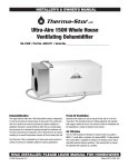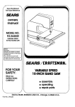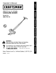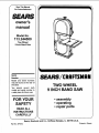
1
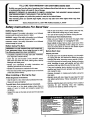
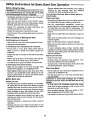
f
Save This Manual
For Future Reference
S£ARS
owner's
manual
Model No.
113,244580
Two Wheel
9 Inch Band Saw
Serial
Number
Model and serial numbers
may be found at the rear of
the base.
You should record both
model and serial number in
a safe place for future use.
FOR YOUR
SAFETY
READ ALL
INSTRUCTIONS
CAREFULLY
SE/ Uq S/CRAFTSMAN
TWO WHEEL
9 INCH BAND SAW
• assembly
• operating
• repair parts
J
Sears, Roebuck
Part No. SP5872
and Co., Hoffman
Estates,
IL. 60179 U.S.A.
Printed in Taiwan
FULL ONE YEAR WARRANTY
ON CRAFTSMAN
BAND SAW
If within one year from the date of purchase, this Craftsman Band Saw fails due to a defect in material
or workmanship, Sears will repair it, free of charge.
WARRANTY SERVICE IS AVAILABLE BY SIMPLY CONTACTING THE NEAREST SEARS SERVICE
CENTER/DEPARTMENT THROUGHOUT THE UNITED STATES,
This warranty applies only while this product is used in the United States.
This warranty
state to state.
gives you specific legal rights, and you may also have other rights which vary from
Sears, Roebuck and Co., D/817 WA Hoffman Estates, IL 60179
Safety Instructions
For Band Saw
Safety Signal Words:
DANGER: means if the safety information is not followed
someone will be seriously injured or killed.
WARNING: means if the safety information is not followed
someone could be seriously injured or killed.
CAUTION: means if the safety information is not followed
someone may be injured.
Before Using The Saw:
I
ous, permanent injury, do not plug the saw in until
I WARNING: to avoid mistakes that could cause seri- I
the following steps have been completed.
• Completely assemble and align saw (see "Assembly"
and "Alignment" section within).
• Learn the use and function of the ON-OFF switch,
table bevel and bevel lock knob, blade guides, backup
bearings and blade guard.
• Review and understand all safety instructions and
operating procedures in this manual.
• Review the maintenance methods for this saw.
• Find and read all the warning labels found on the front
of the saw (shown below).
When Installing
or Moving
the Saw:
Avoid dangerous environment.
• Use the saw in a dry, indoor place protected from rain.
• Keep work area well lighted.
To avoid injury from unexpected saw movement.
• Put the saw on a firm level surface where there is
plenty of room to handle and properly support the
workpiece.
• Support the saw so the table is level and the saw does
not rock.
ADVSmlENClA
ALLOW
TOO L TO
sTOp
BEFORE
ADJUSTING
_EQUE LA
HERRAf£Ek'TA
SE
DETENGAANTES
DEI_.ALIZ_
_JSl"ES
• Bolt the saw to the floor or work surface. Saw may slip,
walk or slide while cutting long or heavy boards.
• Turn saw off and unplug cord before moving the saw.
To avoid injury from electrical
shock.
• Make sure your fingers do not touch the plug's metal
prongs when plugging in or unplugging the saw.
• Never stand on tool. Serious injury could occur if the
tool tips or you accidentally hit the cutting tool. Do not
store any items above or near the tool where anyone
might stand on the tool to reach them.
Before Each Use:
Inspect your saw.
• To avoid injury from accidental starting, turn the switch
off, unplug the saw, and remove the switch key before
changing the setup, removing covers, guards or blade.
• Check for alignment of moving parts, binding of moving
parts, breakage of parts, saw stability, and any other
conditions that may affect the way the saw works.
• If any part is missing, bent or broken in any way, or any
electrical part does not work properly, turn the saw off
and unplug the saw.
• Replace damaged or missing parts before using the
saw again.
• Maintain tools with care, Keep the saw clean for best
and safest performance. Follow instructions for lubricating.
• Remove adjusting keys and wrenches. Form a habit of
checking for and removing keys and adjusting
wrenches from table top before turning it on.
To avoid injury from jams, slips, thrown pieces or
broken blades.
Inspect your blade.
; Do not wear loose clothing, gloves, neckties or jewelry
(rings, wrist watches). They can get caught and draw
you into moving parts.
• Choose the right blade size, style and cutting speed for
the material and the type of cutting you plan to do,
• Wear nonslip footwear.
• Use only recommended accessories. Consult this
owners manual for recommended accessories. Follow
the instructions that come with the accessories. The
use of improper accessories may cause risk of injury to
persons.
• Roll long sleeves above the elbow.
• Make sure the blade teeth point downward, toward the table.
• Make sure the blade guides and thrust bearings are
properly adjusted.
• Make sure the blade tension is properly adjusted.
• Make sure the bevel clamp is tight and no parts have
excessive play.
• To avoid accidental blade contact, minimize blade
breakage and provide maximum blade support, always
adjust the upper blade guide and blade guard to just
clear the workpiece.
Inspect your work area.
• Keep work area clean.
• Cluttered areas and benches invite accidents.
must not be slippery from wax or sawdust.
Floor
• To avoid burns or other fire damage, never use the saw
near flammable liquids, vapors or gases.
Plan Your Work.
• Use the right tool. Don't force tool or attachment to do
a job it was not designed to do.
• Use this band saw to cut only wood, wood like products and plastics.
CAUTION: To avoid blade breakage, fire or other
damage to the saw, never use this band saw to cut
metals,
• To avoid injury from accidental contact with moving
parts, don't do layout, assembly, or set up work on the
saw while any parts are moving.
• Avoid accidental starting. Make sure switch is "OFF"
before plugging saw into a power outlet.
• Plan ahead to protect your eyes, hands, face and ears.
Dress for safety
• Any power saw can throw foreign objects into the eyes.
This can cause permanent eye damage. Wear safety
goggles (not glasses) that comply with ANSI Z87.1
(shown on package). Everyday eyeglasses have only
impact resistance lenses. They are not safety glasses.
Safety goggles are available at Sears retail stores.
Glasses or goggles not in compliance with ANSI Z87.1
could seriously hurt you when they break.
WEAR
YOUR
• Tie back long hair.
• Noise levels vary widely. To avoid possible hearing
damage, wear ear plugs or muffs when using saw for
hours at a time.
• For dusty operations, wear a dust mask along with the
safety goggles.
Inspect your workpiece.
Make sure there are no nails or foreign objects in the
part of the workpiece to be cut.
Use extra caution with large, very small or awkward
workpieces:
• Use extra supports (tables, saw horses, blocks, etc.)
for any workpieces large enough to tip when not held
down to the table top.
• Never use another person as a substitute for a table
extension, or as additional support for a workpiece that
is longer or wider than the basic saw table, or to help
feed, support or pull the workpiece.
• When cutting irregularly shaped workpieces, plan your
work so it will not slip and pinch the blade. A piece of
molding for example, must lie flat or be held by a fixture
or jig that will not let it twist, rock or slip while being cut.
• Properly support round material such as dowel rods, or
tubing. They tend to roll during a cut, causing the blade
to "bite". To avoid this, always use a "V" block or clamp
the work to the miter gage.
• Cut only one workpiece at a time.
• Clear everything except the workpiece and related
support devices off the table before turning the saw on.
Plan the Way You Will Hold the Workpiece
From Start To Finish.
• Do not hand hold pieces so small that your fingers will
go under the blade guard. Use jigs or fixtures to hold
the work and keep your hands away from the blade.
• Secure work. Use clamps to hold work when practical.
It's often safer than using your hand, and frees both
hands to operate the tool.
• Don't overreach. Keep good footing and balance.
Safety Instructions
for Band Saws (continued)
Whenever Sawblade Is Moving:
• Wait for all moving parts to stop.
• Remove switch key.
WARNING: Don't let familiarity (gained from frequent use of your band saw) cause a careless mistake. Always remember that a careless fraction of a
second is enough to cause a severe injury.
When backing up the workpiece, the blade may bind
in the kerr (cut). This is usually caused by sawdust
clogging up the kerf or because the blade comes out
of the guides. If this happens:
• Turn saw "OFF"
• Before starting your cut, watch the saw while it runs. If
it makes an unfamiliar noise or vibrates a lot, stop
immediately. Turn the saw off. Unplug the saw. Do not
restart until finding and correcting the problem.
• Before removing loose pieces from the table, turn saw
off and wait for all moving parts to stop.
Keep Children
• Wait for all moving parts to stop.
• Remove switch key.
• Unplug the saw.
• Remove band saw cover.
• Stick flat blade screwdriver or wedge into the kerf.
Away.
• Turn the upper wheel by hand while backing up the
workpiece.
• Keep all visitors a safe distance from the band saw.
• Make sure bystanders are clear of the band saw and
workpiece.
Don't Force Tool.
Before
Leaving
the Saw.
• Turn the saw off.
• Let the blade reach full speed before cutting.
• Wait for all moving parts to stop.
• It will do the job better and safer at its designed rate.
• Unplug the saw.
• Feed the workpiece into the saw only fast enough to let
the blade cut without bogging down or binding.
° Make workshop child-proof.
Before freeing jammed
• Turn switch "OFF".
- Lock the shop.
- Disconnect master switches.
material.
- Remove the yellow switch key. Store it away from
children and others not qualified to use the tool.
• Unplug the saw.
Glossary Of Terms For Woodworking
Beveling
An angle cutting operation made through the face of the
workpiece.
Push Stick
A device used to feed the workpiece through the saw during narrow ripping type operations and helps keep the
operator's hands well away from the blade.
Resaw
Compound Cutting
A simultaneous bevel and miter crosscutting operation
Crosscut
A cutting operation to reduce the thickness of the workpiece to make thinner pieces.
Resin
A cutting operation made across the width of the workpiece.
FPM
A sticky, sap based substance that has dried.
Feet per minute. Used in reference to surface speed of
blade.
Ripping
A cutting operation along the length of the workpiece.
Sawblade Path
Freehand (as used for band saw)
Performing a cut without the workpiece
ported on the work table.
Gum
properly
The area of the worktable or workpiece directly in line
with the saw blade.
sup-
Set
A sticky, sap based residue from wood products.
Kerf
The distance the tip of the sawblade tooth is bent outward from the face of the blade.
The material removed by the blade in a through cut or the
slot produced by the blade in a nonthrough or partial cut.
Trailing End
The workpiece end last cut by the blade.
Leading End
The end of the workpiece which, is pushed into the cutting tool first.
Mitering
Workpiece
The item on which the cutting operation is being performed. The surfaces of a workpiece are commonly
referred to as faces, ends, and edges.
Worktable
An angle cutting operation made across the width of the
workpiece.
The surface on which the workpiece rests while performing a cutting or sanding operation.
4
Motor Specifications and Electrical Requirements
Power Supply and Motor Specifications
It is recommended that you have a qualified electrician
replace the Two prong outlet with a properly grounded
Three prong outlet.
The A-C motor used in this saw is non-reversibletype, having the followingspecifications:
Grounding Lug
Maximum Developed H.P. ........................................
113
Voltage ....................................................................
120
Amperes ...................................................................
2.5
Hertz (Cycles) ...........................................................
60
Phase ..................................................................
Single
RPM ......................................................................
1750
Rotation of Shaft ............................... Counterclockwise
WARNING:
To avoid electrocution:
Make Sure This Is
3-Prong
Plug
Connected to a
Known Ground
g
Receptacle
Do not let fin-
Adapter
gers touch the terminals of plugs when installing
or removing the plug to or from the outlet.
An adapter, as illustrated, is available for connecting
plugs to 2-prong receptacles.
WARNING: If not properly grounded, this power
tool can cause an electrical shock, particularly
when used in damp locations close to plumbing. If
an electrical shock occurs there is the potential of
a secondary hazard, such as your hands contacting the sawblade.
WARNING: The green grounding lug extending
from the adapter must be connected to a permanent ground such as to a properly grounded outlet
box. Not all outlet boxes are properly grounded.
If the grounding instructions are not completely understood or if you are not sure that your tool or outlet box is
properly grounded, check with a qualified electrician.
WARNING: To avoid electrocution or fire, if power
cord is torn or cut, or damaged in any way, have it
replaced immediately.
NOTE: The adapter illustrated is for use only if you
already have a properly grounded 2-prong receptacle.
Your unit is for use on 120 volts, and has a plug that looks
like the one below.
Motor Safety Protection
NOTE: To avoid motor damage this motor should be
blown out or vacuumed frequently to keep sawdust from
interfering with normal motor ventilation.
9-Prong
Plug
Properly
Grounded
1. This tool should be connected to a 120v, 15 amp
branch circuit with a 15 amp fuse or circuit breaker.
Failure to use the proper size fuse can result in damage to the motor.
2. If the motor fails to start, turn the power switch to the
"OFF" position immediately. Unplug the tool. Check the
sawblade to make sure it turns freely. If the blade is
free, try to start the motor again. If the motor still does
not start, refer to the "Motor Troubleshooting Chart".
Outlet
\
Gr;rUnnd_ng
This power tool is equipped with a 3-conductor cord and
grounding type plug listed by Underwriters' Laboratories.
The ground conductor has a green jacket and is attached
to the motor at one end and to the ground prong in the
attachment plug at the other end. If repair or replacement
of the electric cord or plug is necessary, do not connect
the equipment grounding conductor to a live terminal.
3. If the motor suddenly stalls while cutting wood, turn the
power switch off, unplug the tool and free the blade
from the wood. The motor may now be restarted and
the cut finished.
4. Frequent "blowing" of fuses or tripping of circuit breakers may result if:
a. Motor is overloaded - Overloading can occur if you
feed too rapidly.
b. Low Voltage - Although the motor is designed for
operation on the voltage and frequency specified on
the motor nameplate, normal loads will be handled
safely on voltages not more than 10% above or
below the nameplate voltage. Heavy loads, however,
require voltage at motor terminals equals the voltage specified on nameplate.
This plug requires a mating 3-conductor grounding type
outlet as shown. This outlet must be installed and
grounded in accordance with all local codes and ordinances.
WARNING: To avoid electrocution, if the outlet you
are planning to use for this power tool is of the two
prong type, Do Not Remove Or Alter The Grounding Prong In Any Manner. Use an adapter as shown
below and always connect the grounding lug to a
known ground.
c. Improper or dull blades are used.
5
Motor Specifications and Electrical Requirements (continued)
5. Motor troubles may be traced to loose or incorrect connections, overload, reduced input voltage (such as
small size wire in the supply circuit) or to overly long
supply circuit wire. Always check the connections, the
load and the supply circuit whenever motor fails to perform satisfactorily. Check wire size and length with the
Wire Size Chart as follows.
heating and motor burn-out, use the table below to determine the minimum wire size (A.WG.) extension cord.
Use only 3-wire extension cords that have 3-prong
grounding type plugs and 3-pole receptacles which
accepts the tools plug.
Extension
Wire Sizes
Cord Length
110-120V
0 - 25 Ft.
26 - 50 Ft.
NOTE; Make sure the proper extension cord is used and
is in good condition.
The use of any extension cord will cause some loss of
power. To keep this to a minimum and to prevent over-
A.W.G.
18
16
Table of Contents
Safety Instructions For Band Saw .................................
Safety Signal Words: .................................................
Before Using The Saw: ..............................................
When Installing or Moving the Saw: ..........................
Before Each Use: .......................................................
Plan Your Work ..........................................................
Dress for safety ..........................................................
Plan the Way You Will Hold the Workpiece From
Start To Finish .........................................................
Mounting the Band Saw ..............................................
14
Mounting Band Saw to Workbench ......................... 14
Clamping Band Saw to Workbench ......................... 15
Mounting Band Saw to Accessory Legset
Cat. No. 9-22244 ...................................................
15
2
2
2
2
2
3
3
Legset Mounting Holes for Band Saw ..................... 15
Getting to Know Your Band Saw ............................ 16-17
Safety Instructions for Basic Band Saw Operation ...... 18
Before Using the Saw: .............................................
18
When Installing or Moving the Saw: ........................ 18
Before Each Use: ....................................................
18
Plan Your Work ........................................................
18
Dress For Safety ......................................................
19
Plan the Way You Will Hold the Workpiece From
Start To Finish; ......................................................
19
Whenever Sawblade is Moving ............................... 19
Before Leaving the Saw...........................................
19
Basic Band Saw Operations ........................................ 20
General Cutting .......................................................
20
Circle Cutting ...........................................................
20
Relief Cuts ...............................................................
20
Maintenance ................................................................
21
Tires .......................................................................
21
General Maintenance ..............................................
21
Motor ..., ...................................................................
21
Lubrication ...............................................................
21
Sears Recommends the Following Accessories ......... 21
Troubleshooting ...........................................................
22
General ....................................................................
22
Motor .......................................................................
23
3
Whenever Sawblade is Moving .................................. 4
Before Leaving the Saw .............................................
4
Glossary Of Terms For Woodworking ............................ 4
Motor Specifications and Electrical Requirements ........ 5
Power Supply and Motor Specifications .................... 5
Motor Safety Protection ............................................. 5
Wire Sizes ..................................................................
6
Table of Contents ...........................................................
6
Unpacking and Checking Contents ............................... 7
Tools Needed .............................................................
7
Unpacking ..................................................................
7
List of Loose Parts .....................................................
8
Assembly .......................................................................
9
Installing the Table .....................................................
9
Installing the Blade ..................................................
10
Alignment (Adjustments) ............................................. 11
Tensioning the Blade ...............................................
11
Tracking the Blade ...................................................
11
Adjusting Upper Blade Guard Assembly ................. 12
Aligning the Table Square to the Blade .................... 12
Adjusting the Blade Guides and Back-Up Bearing .. 13
Adjusting Motor Belt Tension ................................... 14
Repair Parts ................................................................
6
24
Unpacking and Checking Contents
Tools Needed
Tools required for assembly and alignment:
• #2 Phillips screwdriver
• Adjustable wrench.
• Combination Square
Combination
Draw Light
Line on Board
#2 Phillips Screwdriver
6" Adjustable Wrench
Combination
Square
A I°iill
il i_ieiieltlw
Square Must be True
Straight Edge of
Board 3/4" Thick
This Edge Must be
i ii rl iiilr e
is Flipped Over in Dotted Position
Unpacking
WARNING: To avoid injury from unexpected starting or electrical shock, do not plug the saw in until
all assembly and alignment steps are complete.
The power cord must remain unplugged whenever
you are working on the saw.
Unpacking and Checking Contents
1. Separate all "loose parts" from packaging materials
and check each item with "Table of Loose Parts" to
make sure all items are accounted for, before discarding any packing material.
WARNING: If any parts are missing, do not attempt
to assemble the band saw, plug in the power cord,
or turn the switch on until the missing parts are
obtained
and
are
installed
correctly.
2. Sometimes small parts get lost in packaging materials.
Do not throw away any packaging until your saw is put
together. If you are missing a part, check packaging
before contacting Sears.
7
Unpacking and Checking Contents (continued)
List of Loose Parts
A
NOTE: Before beginning assembly, check that all parts
are included. If you are missing any part, do not assemble the saw. Contact your Sears Service Center to get the
missing part. Sometimes small parts can get lost in packaging material. Do not throw away any packaging until
saw is put together. Check packaging for missing parts
before contacting Sears. A complete parts list "Repair
Parts" is at the end of the manual. Use the list to identify
the number of the missing part.
The following parts are included:
Item
A
B
C
D
E
Description
Qty.
Basic Saw Assembly...........................................
Owners Manual ...................................................
Saw Table Assembly ...........................................
Blade...................................................................
1
1
1
1
Loose Parts Bag .................................................
1
Containing the following parts:
Wing Nut 1/4-20 ..................................................
1
Screw, Truss Hd. 1/4-20 x 3/4 ............................. 1
Washer 1/4 .........................................................
1
Wrench, 1/8" Hex"L" ......................................... 1
Screw, Flat head 1/4-20 x 7/8 ............................. 3
Nut hex 1/4-20 ....................................................
3
Lockwasher 1/4 ...................................................
3
Key Switch ..........................................................
1
Screw 3/16-24 x 3/8 ......................................... ,..1
Indicator ..............................................................
1
F
G
H
J
K
L
M
N
P
R
D
E
G
K
L
@
N
8
P
Assembly
WARNING: For your own safety, never connect
plug to power source outlet until all assembly
steps are complete, and you have read and understood the safety and operational instructions.
From the loose parts find the following items:
Item No.
Description
Qty
A
1/4-20 x 7/8" Flat head screws ...................... 3
B
1/4-20 Hex nuts ............................................. 3
C
1/4 Lockwasher ............................................. 3
D
1/4-20 x 3/4 Truss head screw ....................... 1
E
1/4-20 Wing nut ............................................. 1
1/4 Washer ....................................................
1
F
G
Switch Key .....................................................
1
H
1/8" He× "L" Wrench ...................................... 1
J
3/16-24 x 3/8 Screw ....................................... 1
K
Indicator .........................................................
1
L
Table w/Insert (not pictured) .......................... 1
M
Sawblade (not pictured) ................................. 1
Installing
D
H
G
the Table
Get table from among loose parts.
1. Place table with insert onto trunnion and align holes in
the table to those in the trunnion. Use the three 1/4-20
fiat head screws, three 1/4 Iockwashers and the three
1/4-20 he× nuts to secure table. Tighten nuts with an
open end or an adjustable wrench.
2. Loosen the table lock knob and turn the table tilt knob
to change the angle of the table. If the table is loose or
too tight, adjust the hex head bolt with an open end or
an adjustable wrench until firm, smooth table tilt operation is achieved.
"Hex Head
Bolt
Table
Knob
3. Assemble the bevel indicator to the saw frame using
the 3/16-24 x 3/8 screw.
Bevel
Indicator
Assembly (continued)
Installing the Blade
I
I unplug
WARNING:
saw Turn
beforeoffremoving
saw, remove
or installing
switch blade.
key andl
1. Open front
latches.
cover by pushing in upper and lower
2. Loosen the upper slide lock knob and position the
blade guard/guide assembly about half way between
the table and the frame. Tighten the lock knob:
Slide
Lock
Knob
CAUTION: To avoid serious eye injury or scrapes, if
the blade should suddenly uncoil, wear safety goggles. Carefully uncoil the blade holding it at arms
length.
Tension Adjusting
Knob
3. Uncoil the blade.
4. Slide the blade into the slot of the table with the teeth
facing toward front of saw and down toward the table.
5. RaGe the blade on both wheels. Center the blade on
the rubber tires.
NOTE: If the blade will not reach around both wheels,
lower the upper wheel by turning the tension adjustment
knob counterclockwise.
Head
Screw
NOTE; Close the band saw cover after blade is properly
installed.
f
,J
6. Assemble the truss head screw, washer and wing nut
to the table. The washer and wing nut are positioned
below the table.
10
Washer
Alignment (Adjustments)
Tensioning
Tension Adjusting Knob
the Blade
be permanently damaged. Wear your safety gogI WARNING: Cut material can be thrown. Eyes can
gles.
I WARNING:
Turn
off saw, remove switch key and
unplug before
adjusting.
1. Turn blade tension adjusting knob clockwise until the
proper section of knob stern is aligned with top of band
saw frame. See illustration for blade size and "Alignment" section.
NOTE; Be careful not to overtension the blade, Too much
tension may tend to cause blade breakage. Too littletension may cause the blade to slip on the wheels. The tension adjusting knob has a knurled section on it. These
adjustment areas are approximate and may change
slightly depending on actual blade length.
Topj_
3/8" Blade
1/4" Blade
Knurled j
['
Section I____]
I ''_'---
1/8'' Blade
Tracking the Blade
I
I WARNING:
Turn
off saw, remove switch key and I
unplug before
adjusting.
NOTE: Blade tension must be properly adjusted before
tracking the blade.
1. Open the cover and slowly turn the upper wheel clockwise by hand and watch the blade on the upper tire. If
the blade moves away from the center of the tire the
tracking must be adjusted.
2. Insert the 1/8" hex wrench into the tracking adjustment
screw located on the back of the saw behind the upper
wheel.
a. If the blade moved toward the front of the saw turn
the adjustment screw in (clockwise) while turning
the wheel by hand, until the blade rides in the center
of the tire.
Tracking Adjustment
7
Set Scre__
F
\\
b. If the blade moved away from the front of the saw,
turn the adjustment screw out (counterclockwise)
while turning the wheel by hand, until the blade rides
in the center of the tire.
Blade
3. Check the position of the blade on the lower tire. The
blade should be completely on the tire. If not, adjust
the tracking until the blade is on both tires.
Wheel
3ack of
4. Rotate the upper wheel by hand in a clockwise direction for a few more turns. Make sure the blade stays in
the same location on the tires. Readjust if necessary,
until blade is tracking properly.
1/8" Blade on Back Half
Of Upper Wheel
NOTE: The 1/8" blade may not track properly in the center of the wheel. It may be better to track this blade on the
back half of the upper wheel. (See Illustration)
5. Replace hex wrench in holder located on the inside of
the front cover. Close cover making sure the upper and
lower latches catch.
11
Alignment (Adjustments)
Adjusting
Upper
Blade
Guard
(continued)
Assembly
Upper Slide
Lock Knob
The upper blade guard assembly should always be set
about 1/8" above or as close as possible to the top surface of the workpiece being cut.
1. Loosen the upper slide lock knob.
Upper Guard Assembly
2. Rotate the upper slide adjusting knob to position the
guard assembly to the desired position.
3. Tighten the upper slide lock knob.
Upper Slide
Adjusting Knob
Aligning
the Table Square
to the Blade
I WARNING:
Turn
off saw, remove switch key and
unplug before
adjusting.
1. Loosen the upper slide lock knob and position the
guide assembly all the way up. Tighten the lock knob.
2. Loosen table lock knob.
3. Place a small square on the table beside the blade as
illustrated.
4. Holding the left edge of the table (near the zero stop
set screw), tilt the table up or down to align table 90 ° to
blade (0 ° position). Tighten lock knob,
5. Adjust the zero stop set screw using the 1/8" hex
wrench until the set screw just touches the frame.
6. Check squareness of blade to table. Make readjustments if necessary.
7. Check table bevel indicator for accuracy, Loosen screw
and adjust if necessary. Retighten screw.
Zero Stop
Set Screw
12
Adjusting the Blade Guides and Back-Up
Bearing
I
Upper
I
I WARNING:
Turn
off saw,
switch key and I
unplug before
making
any remove
adjustments.
P
Bearing
Cap Screw
NOTE: The upper and lower blade guides and back-up
bearings support the band saw blade during cutting operations. The adjustment of the guides and bearings should
be checked whenever a different blade is installed.
Guide
1. Adjust the position of the blade guide support housings. Loosen the upper blade guide support housing
cap screw using a 1/8 Hex "L" wrench.
Support Housing
Cap Screw
2. Slide the upper blade guide support housing on the
shaft until the front edge of the blade guides are about
1/32" behind the gullet of the blade. Tighten the cap
screw.
3. Repeat for the lower blade guide support housing. (You
may need to adjust the blade tracking before making
this adjustment.)
NOTE; If the front face of the blade guides are not 1/32"
behind the gullet of the blade the blade teeth will hit the
blade guides and this will ruin the blade. Proper adjustment of the upper and lower blade guide support housings will prevent this from happening.
Upper
Upper
Back-u
Bearing
Upper Blade
Guide
Su
Housing
3. Adjust the blade guides. Loosen the two cap screws
that lock the upper blade guides into the housing and
press the two guides evenly against the sides of the
blade but do not pinch the blade. Release the guides
and rotate the upper wheel slightly clockwise moving
the blade downward. Make sure one guide is not further away from the blade than the other. Tighten both
cap screws.
I
I
Bearing
Cap Screw
Blade
Guide Support
Housing
Cap Screw
BI;
4. Repeat on the lower blade guides.
NOTE; Ideally, the space between the blade and the
guides should be approximately the thickness of a dollar
bill. This will provide maximum blade support and control
during cutting operations
5. Adjust the upper and lower back-up bearings. Loosen
the back up bearing cap screw using a 1/8" Hex "L"
wrench.
6. Move the back-up bearings to within 1/32" or less of
the back edge of the blade.
NOTE: The back-up bearing is used to support the back
edge of the blade while cutting. The blade should just
barely contact the bearings when you stop cutting.
Lowe
Guide
Support Housin
Lower Back-u
Bearing
13
Lower Blade Guide
Support Housing
CaD Screw
///./,@v/_
U
:r Back-Up
Bearing Cap Screw
Alignment (Adjustments)
(continued)
2. If adjustment is necessary, loosen the upper motor
bolt and lower motor pivot bolt. Move the motor to correct the belt tension. Retighten both motor bolts.
Adjusting Motor Belt Tension
WARNING: Turn off saw, remove switch key and I
unplug before making any adjustments.
I
3. Recheck belt tension and readjust as necessary. Close
the front cover of saw when procedure is completed.
1. Test for proper belt tension. Open front cover. Rotate
lower wheel so you can access both sides of the motor
pulley. Place your thumb and index finger over the outside of the belt. Squeeze the two sides of the belt
together. There should be about 1/4" of give to the belt.
Upper Motor Bolt
NOTE: Excessive tightness of belt may cause increased
noise and overload motor. Excessive looseness of belt
may cause belt to fail prematurely.
Lower Motor Pivot Bolt
Mounting the Band Saw
Mounting
Band
Saw to Workbench
If band saw is to be used in a permanent location, it
should be fastened securely to a film supporting surface
such as a workbench.
If mounting to a workbench, holes should be drilled
through supporting surface of the workbench using
dimensions illustrated.
1. Each leg should be bolted securely using 5/16" diameter machine screws, Iockwashers, and 5/16" hex nuts
(not included). Screw length should be 1-3/4" plus the
thickness of the bench top.
2. Locate and mark the holes where band saw is to be
mounted.
6"
I
3/8" DIAMETER
(4) HOLES
1'
-_-
3. Drill (4) 3/8" diameter holes through workbench.
I
'
tt"
--_-_
4. Place band saw on workbench aligning holes in feet
with holes drilled in workbench.
5. Install all four 5/16" screws, Iockwashers and nuts and
tighten.
NOTE: All bolts should be inserted from the top. Install
the washers and nuts from the underside of the bench.
An alternate method of mounting is to fasten band saw to
a mounting board. The board should be of sufficient size
to avoid tipping of saw while in use. Any good grade of
plywood or chipboard with a 3/4" minimum thickness is
recommended. Thinner chipboard can break.) Once the
saw is mounted, securely clamp the board to the workbench using "C" clamps.
24" MIN.
±
18" MIN,
WARNING: Supporting surface where band saw is
mounted
should be examined
carefully after
mounting to insure that no movement during use
can result, If any tipping or walking is noted, secure
workbench or supporting surface before operating
band saw.
5"
11"
14
Clamping Band Saw to Workbench
The band saw can be clamped directly to a workbench
using two (2) or more "C" clamps on base of unit.
Mounting
Band Saw to Accessory
o
Oaoa
O
Legset Cat. No. 9-22244
,,,d
O O
i
Attach to holes indicated by "m"
Legset
Mounting
Holes
for Band
Saw
Recommended mounting hardware (not included)
Description
,5/16-18
x 1-1/2
he× hd, bolts ........................................
5/16 fiat washers ..........................................................
5/16 Iockwashers .........................................................
5/16-18 hex nuts ..........................................................
Qty
,4
4
4
4
t6
Getting to Know Your Band Saw
1. Blade Guides - Supports the blade and keeps it from
twisting during operation. An adjustment is necessary
when blades are changed or replaced.
2. Back up bearings support the back of blade
3. Upper Slide Lock and Adjustment Knobs - Loosen
outer knob to unlock. Turn inner knob to adjust.
Retighten outer knob to lock upper blade guard/slide
in place.The upper blade guide assembly should just
clear the workpiece while cutting. Always adjust the
upper guide assembly and lock by tightening the
upper slide lock knob before turning on the band saw.
4. Table Lock and Adjustment Knobs - Loosen outer
knob to unlock. Turn inner knob to adjust. Retighten
outer knob to lock table in place.
5, Tilt (Bevel) Scale - Shows degree table is tilted for
bevel cutting.
6. Tension Adjustment Knob - Controls the amount of
blade tension when changing blades.
10
7. Tracking Adjustment Set Screw - Adjust to Keep
blade running in center of wheels.
8. Sawdust Ejection Port - Sawdust is eliminated from
inside machine. Also, makes an excellent hook-up for
a Wet/Dry vac.
9. Front cover may be opened for making adjustments
to machine.
10. Wrench Holder - Keeps 1/8" hex "L" wrench conveniently stored for blade guide and tracking adjustments.
11. Wheel Brushes - Cleans dust from wheels during
operation.
12. Blade Guard -The blade guard protects the operator
from contacting the blade. The blade guard should be
adjusted as close as possible to the top of the workpiece.
Wrench Holder
6
9 Front Cover
Tension Adjustment Knob
3
12 Blade Guard
Upper Slide
Lock and
Adjustment
Knobs
Tracking
7 Adjustment
Set
1 Blade
Guides
(Above and
Below Table)
Back Up
Bearings
(Above and
Below Table)
Ejection
Port
t 3 On-Off Switch
wlLockin
9 Key
4 Table Lock and
Adjustment
Knob
16
5 Tilt
Scale
13. On-Off Switch - The On-Off switch has a locking feature. This feature is intended to help prevent unauthorized and possible hazardous use by children and
others.
1. To turn band saw "On" insert key into switch.
NOTE: Key is made of yellow plastic, located in
loose parts bag.
2. Insert finger under switch lever and Pull end of
switch out.
3. To turn band saw "Off" Push lever in.
I until
WARNING:
it has come
Never toleave
a complete
the band
stop.
saw unattended
4. To lock switch in Off position hold switch in with one
hand and remove key with other hand.
WARNING" For your own safety, always lock the
switch "Off" when band saw is not in use, remove
the key and keep it in a safe place. In the event of a
power failure (all of your lights go out) turn switch
off, remove the key and store it away from the band
saw. This will prevent the machine from starting up
again when the power comes back on.
17
Safety Instructions for Basic Band Saw Operation
Before Using the Saw:
• Remove adjusting keys and wrenches. Form a habit of
checking for and removing keys and adjusting
wrenches from table top before turning it on.
To avoid injury from jams, slips or thrown pieces or
broken blades.
WARNING: to avoid mistakes that could cause serious, permanent injury, do not plug the saw in until
the following steps have been completed.
• Completely assemble and align saw (see "Assembly"
and "Alignment" section within).
Inspect your blade.
• Choose the right blade size, style and cutting speed for
the material and the type of cutting you plan to do.
• Use only recommended accessories. Consult this
owners manual for recommended accessories. Follow
the instructions that come with the accessories. The
use of improper accessories may cause risk of injury to
persons.
• Learn the use and function of the ON-OFF switch,
table bevel and bevel lock knob, blade guides, backup
bearings, guide bar lock knob and blade guard.
• Review and understand all safety instructions and
operating procedures in this manual.
• Review the maintenance methods for this saw.
• Find and read all the warning labels found on the front
of the saw.
When
Installing
or Moving
• Make sure the blade teeth point downward, toward the
table.
the Saw:
• Make sure the blade guides and thrust bearings are
properly adjusted.
Avoid dangerous environment,
• Make sure the blade tension is properly adjusted.
• Make sure the bevel clamp is tight and no parts have
excessive play.
• To avoid accidental blade contact, minimize blade
breakage and provide maximum blade support, always
adjust the upper blade guide and blade guard to just
clear the workpiece.
• Use the saw in a dry, indoor place protected from rain.
• Keep work area well lighted.
To avoid injury from unexpected saw movement.
• Put the saw on a firm level surface where there is
plenty of room to handle and properly support the
workpiece.
• Support the saw so the table is level and the saw does
not rock.
Inspect your work area.
• Keep work area clean.
• Cluttered areas and benches invite accidents. Floor
must not be slippery from wax or sawdust.
• Bolt the saw to the floor or work surface. Saw may slip,
walk or slide while cutting long or heavy boards.
• Turn saw off and unplug cord before moving the saw.
• To avoid burns or other fire damage, never use the saw
near flammable liquids, vapors or gases.
To avoid injury from electrical shock.
• Make sure your fingers do not touch the plug's metal
prongs when plugging in or unplugging the saw.
Plan Your Work:
• Use the right tool. Don't force tool or attachment to do
a job it was not designed to do.
• Never stand on tool. Serious injury could occur if the
tool tips or you accidentally hit the cutting tool. Do not
store any items above or near the tool where anyone
might stand on the tool to reach them.
Before
Each
• Use this band saw to cut only wood, wood like products and plastics.
Use:
I
damage to the saw, never use this band saw to cut
I CAUTION:
To avoid blade breakage, fire or other I
metals.
Inspect your saw.
• To avoid injury from accidental starting, turn the switch
off, unplug the saw, and remove the switch key before
changing the setup, removing covers, guards or blade.
• To avoid injury from accidental contact with moving
parts, don't do layout, assembly, or set up work on the
saw while any parts are moving.
• Avoid accidental starting. Make sure switch is "OFF"
before plugging saw into a power outlet.
• Check for alignment of moving parts, binding of moving
parts, breakage of parts, saw stability, and any other
conditions that may affect the way the saw works.
• Plan ahead to protect your eyes, hands, face and ears.
• If any part is missing, bent or broken in any way, or any
electrical part does not work properly, turn the saw off
and unplug the saw.
• Replace damaged or missing parts before using the
saw again.
• Maintain tools with care. Keep the saw clean for best
and safest performance. Follow instructions for lubricating.
18
Safety Instructions for Basic Band Saw Operation (continued)
Dress For Safety
Plan the Way You Will Hold the Workpiece
From Start To Finish.
• Any power saw can throw foreign objects into the eyes.
This can cause permanent eye damage. Wear safety
goggles (not glasses) that comply with ANSI Z87.1
(shown on package). Everyday eyeglasses have only
impact resistance lenses. They are not safety glasses.
Safety goggles are available at Sears retail stores.
Glasses or goggles not in compliance with ANSI Z87.1
could seriously hurt you when they break..
WEAR
• Do not hand hold pieces so small that your fingers will
go under the blade guard. Use jigs or fixtures to hold
the work and keep your hands away from the blade.
• Secure work. Use clamps to hold work when practical.
It's often safer than using your hand, and frees both
hands to operate the tool.
• Don't overreach. Keep good footing and balance.
Whenever Sawblade Is Moving:
YOUR
WARNING: Don't allow familiarity (gained from frequent use of your band saw) cause a careless mistake. Always remember that a careless fraction of a
second is enough to cause a severe injury,
• Before starting your cut, watch the saw while it runs. If
it makes an unfamiliar noise or vibrates a lot, stop
immediately. Turn the saw off. Unplug the saw. Do not
restart until finding and correcting the problem.
Keep children away.
• Keep all visitors a safe distance from the band saw.
• Make sure bystanders are clear of the band saw and
workpiece.
Don't force tool.
• Let the blade reach full speed before cutting.
• It will do the job better and safer at its designed rate.
• Feed the workpiece into the saw only fast enough to let
the blade cut without bogging down or binding.
Before freeing jammed material,
• Turn switch "OFF".
• Do not wear loose clothing, gloves, neckties or jewelry
(rings, wrist watches). They can get caught and draw
you into moving parts.
• Wear nonslip footwear.
• Tie back long hair.
• Roll long sleeves above the elbow.
• Noise levels vary widely. To avoid possible hearing
damage, wear ear plugs or muffs when using saw for
hours at a time.
• For dusty operations, wear a dust mask along with the
safety goggles.
Inspect your workpiece.
Make sure there are no nails or foreign objects in the
part of the workpiece to be cut.
• Unplug the saw.
• Wait for all moving parts to stop.
• Remove switch key.
When backing up the workpiece, the blade may bind
in the kerf (cut). This is usually caused by sawdust
clogging up the kerf or because the blade comes out
of the guides. If this happens:
• Turn saw "OFF".
Use extra caution with large, very small or awkward
workpieces:
• Use extra supports (tables, saw horses, blocks, etc.)
for any workpieces large enough to tip when not held
down to the table top.
• Never use another person as a substitute for a table
extension, or as additional support for a workpiece that
is longer or wider than the basic saw table, or to help
feed, support or pull the workpiece.
•
•
•
•
•
• When cutting irregularly shaped workpieces, plan your
work so it will not slip and pinch the blade. A piece of
molding for example, must lie fiat or be held by a fixture
or jig that will not let it twist, rock or slip while being cut.
Wait for all moving parts to stop.
Remove switch key.
Unplug the saw.
Remove band saw cover.
Stick fiat blade screwdriver or wedge into the kerr.
• Turn the upper wheel by hand while backing up the
workpiece.
Before removing loose pieces from the table, turn saw off
and wait for all moving parts to stop.
• Properly support round material such as dowel rods, or
tubing. They tend to roll during a cut, causing the blade
to "bite". To avoid this, always use a "V" block or clamp
the work to the miter gage.
Before Leaving
the Saw.
• Turn the saw off.
• Wait for all moving parts to stop.
• Cut only one workpiece at a time.
• Unplug the saw.
• Make workshop child-proof.
- Lock the shop.
- Disconnect master switches.
-Remove the yellow switch key. Store it away from
children and others not qualified to use the tool.
• Clear everything except the workpiece and related
support devices off the table before turning the saw on.
19
Basic Band Saw Operations
General Cutting
J
safety instructions in "Safety Instructions for Band
I CAUTION: For your safety, comply with all the l
Saw" section before using the band saw.
A band saw is a "curve cutting" machine.
It is also used for straight-line cutting operations such as
crosscutting, ripping, mitering, beveling, compound cutting and resawing.
Operation
Cross Cutting
Ripping
Mitering
Beveling
Compound Cutting
Circle Cutting
Resawing
Curve Cutting
Recommended Blade Size
(Inches)
1/4, 3/8
3/8
114,318
1/4,3/8
1/4,3/8
See Below
3/8
1/4, 1/8
Circle Cutting
1. Adjust the upper guides to vertically clear the workpiece by approximately 1/8".
2. Use both hands while feeding the work into the blade.
Hold the workpiece firmly against the table. Use gentle
pressure, and do not force the work, but allow the
blade to cut.
3. The smallest diameter that can be cut out is determined by the width of the blade. For example, a 1/4inch wide blade will cut a minimum diameter of approximately 1-1/2-inch. A 1/8" blade will cut a minimum
diameter of 1/2".
Relief Cuts
Relief cuts are made when an intricate curve (too small a
radius for the blade) is to be cut. A relief cut is made by
cutting through the scrap section of workpiece to curve in
pattern line, then carefully backing blade out. Several
relief cuts should be made for intricate curves, then follow
pattern line as sections are cut off curve "relieving" blade
pressure.
Workpiece
1
NOTE: Blade guard is raised and right hand moved for
clarity of picture only.
Pattern Line
2O
!
Relief Cuts
Maintenance
General
I
Maintenance
and remove plug from power source outlet before
I WARNING: For your own safety, turn switch "Off" I
maintaining or lubricating your band saw,
Keep your band saw clean. Remove the sawdust from
the inside. Vacuum or blow out saw frequently.
Maintenance
Do not allow filth to build up on the table the guides or the
back-up bearings. Clean them with Craftsman Gum and
Pitch Remover.
I
I DANGER:
is spinning.Never put lubricants on the blade while it I
I
NOTE: Do not immerse the back-up bearings in the gum
and pitch remover.
ing or electrical shock, unplug the power cord
I WARNING: To avoid injury from unexpected start- I
before workinq on the saw.
Put a thin coat of paste wax on the table so that the wood
slides easily while cutting.
Tires
Motor
Pitch and sawdust that build up on the tires should be
removed with a stiff brush or scraped with a piece of
wood.
Frequently blow or vacuum out any sawdust from the
motor. Follow lubrication instruction on the motor label.
NOTE: To avoid damaging the tires do not use a sharp
knife or any kind of solvent.
I wear
CAUTION:
avoid eye
injury
from out
blowing
debris, I
safetyTo
goggles
when
blowing
sawdust.
When the tires become worn they should be replaced.
When replacing the tires, stretch them around the wheels
but do not glue them on.
I WARNING:
fire, immediI
ately replaceToa avoid
worn, electrocution
cut or damagedor power
cord.
Lubrication
All of the ball bearings are packed with grease at the factory. They require no further lubrication.
Sears Recommends
the Following Accessories
Sears may recommend other accessories not listed in
the manual. See your nearest Sears store for other
accessories.
Prohibited Accessories
ries, use only accessories shown on the recomI WARNING:
To avoid list
injury
from
unsafe accessomended accessories
in this
manual.
Miter Gauge ........................................................
9-24214
Blades (59-1/4" length) .............................. See Catalog
Leg Set ...............................................................
9-22244
Power Tool handbook .................... 9-29114 and 9-29115
Do not use any accessory unless you have received and
read complete instructions for its use.
21
Troubleshooting
WARNING: For your own safety, turn switch "Off" and remove plug from power source outlet before trouble
shooting your band saw/sander.
General
Trouble
Probable Cause
Remedy
Blade does not run in the
approximate center of the
upper wheel.
1. Not tracking properly.
Band Saw slows when cut-
1. Belt too loose.
1. Adjust belt tension, see "Alignment section, "Adjust2. Cutting too small a radius.
ing Motor Belt".
3. Dull blade.
2. Stop feeding, and pull the material away from the
blade until the band saw returns to normal speed.
4. Overloading motor.
3. Replace blade.
4. Slow down, trying to cut too fast.
ting
Blades breaking
Blade dulls too quickly.
Band saw vibrates.
.
1. Adjust tracking, see Alignment section, "Tracking the
Blade".
Too much tension on
blade.
1. Adjust tension. See "Alignment section, "Tensioning
the Blade".
2. Kink in blade caused by
cutting too small a radius
or turning the material too
fast when cutting.
2. Use correct cutting technique. See "Basic Band Saw
Operation" section.
1. Blade guides set too close
to teeth.
2. Cutting incorrect material
1. Adjust upper and lower blade guides. See "Alignment" section "Adjusting the Blade Guides and Backup Bearing".
1. Too much tension on
motor belt
1. Adjust according to "Adjusting
tion.
Motor Belt" sec-
CAPACITOR
RED
WHITE
Z_
BLACK
BLACK
GREEN
J_
GROUND SCREW
Circuit
Diagram
22
WHITE
POWER CORD
Motor
NOTE: Motors used on wood-working tools are particularly susceptible to the accumulation of sawdust and wood chips
and should be blown out or "vacuumed" frequently to prevent interference with normal motor ventilation and proper
operation of the centrifugally-operated starting switch.
Trouble
Probable Cause
Remedy
Excessive noise
1. Motor
1. Have motor checked by qualified service technician. Repair service is available at your nearest Sears store.
Motor fails to develop full
power. Note Low Voltage:
Power output of motor
decreases rapidly with
decrease in voltage at
motor terminals. For
example, a reduction of
10% in power cord line
voltage causes a 19%
reduction in maximum
1. Circuit overloaded with light,
appliances and other motors.
2. Undersize wires or circuit too
long.
3. General overloading of power
company facilities.
1. Do not use other appliances or motors on
same circuit when using the saw.
2. Increase wire sizes, or reduce length of wiring.
See "Motor specifications and Electrical
Requirements" section.
3. Request a voltage check from the power company.
1. Low voltage.
1. Request voltage check from the power company. Check size of circuit wiring.
2. Have motor repaired or replaced.
3. Blow out sawdust from motor. Have motor
repaired.
motor power output. A
20% reduction in power
cord line voltage causes a
36% reduction in maximum motor power output.
Motor starts slowly or fails
to come up to full speed.
2. Windings burned out or open.
3. Starting switch not operating.
Motor overheats
. Motor overloaded.
2. Improper cooling (air circulation restricted through motor
due to sawdust accumulation).
Starting switch in motor
will not operate.
1. Burned switch contacts (due to
extended hold-in periods
caused by low line voltage,
etc.)
2. Shorted capacitor.
3. Loose or broken connections.
. Feed work
slower into blade.
2. Clean out sawdust to provide normal air circulation through motor. See "Maintenance" section.
.
Have switch replaced and request a voltage
check from the power company.
2. Have capacitor tested and replace if defective.
3. Have wiring checked and repaired.
Motor stalls (resulting in
blown fuses or tripped circuit breakers).
1. Starting switch not operating.
2. Voltage too low to permit motor
to reach operating speed.
3. Fuses or circuit breakers do
not have sufficient capacity.
1. Have switch replaced.
2. Request voltage check from the power company.
3. Install proper size fuses or circuit breakers.
Frequent opening of fuses
or circuit breakers.
1. Motor overloaded.
2. Fuses or circuit breakers do
not have sufficient capacity.
3. Starting switch not operating
(motor does not reach speed).
1. Feed work slower into blade.
23
2. Install proper size fuses or circuit breakers.
Check that wiring will handle load.
3. Have switch replaced. Blow out sawdust.
Parts List For Craftsman
::o
9-inch Band Saw
Model No. 113.244580
Figure I
9'
==
38'
j6
39
7
5O
//
63
8
9 10
I /l_J
11
4_
44
\
43
45
\
5O
/
4_
\
58
59
/\
/
51
48
38
37
34
I t_tt
52
9 1011
24
36
26
25
Parts List For Craftsman
9 Inch Band Saw Model No. 113.244580
Always Order By Part Number-
Not By Key Number
Figure I - Drive Assembly
Key
No.
tJ!
1
2
3
4
5
6
7
8
9
10
11
12
13
14
15
16
17
18
19
20
21
22
23
24
25
26
27
28
29
30
31
32
33
34
35
36
37
38
Parts
Part No.
Description
Key
No.
Part No.
824042
STD551031
824041
824040
824085
806036-1
824059
824060
824061
STD551025
824072
824082
824056
821555
813989-1
824073
iSTD523110
STD551131
824075
824083
824079
824078
824068
824070
824071
STD541025
STD541625
60530
824074
824144
STD541031
1824069
1824065
820265
STD522507
STD551125
824063
824062
Knob Tension
* Washer 21/64 x 47/64 x 1/16
Spring Tension
Cover Knob
Frame
Screw Set Oval 1/4-20 x 5/8
Shaft Gear
Knob Drive
Spring Knob
* Washer 1/4 x5/8 x 1/16
Knob Lock
Screw Pan Hd. 3/16-24 x 3/8
Plate Cover
Relief Strain
Cord w/Plug
Motor
* Screw Hex hd. 5/16-18 x 1
* Lockwasher 5/16
Screw Flat Hd. 1/4-20 x 24mm
Table
Washer Spring
Screw Shoulder Washer Hd. 1/4-20
Trunnion
Shaft Trunnion Lock
Knob Table Tilt
* Nut Hex 1/4-20
* Nut Wing 1/4-20
Screw Truss Hd. 1/4-20 x 3/4
Insert Table
Pulley Motor
* Nut Hex 5/16-18
Indicator Bevel
Screw Cap 3/16-24 x 1/2
Foot Frame
* Screw Hex Hd. 1/4-20 x 3/4
*Lockwasher 1/4
Block Guide
Support Guide Block
39
40
41
42
43
44
45
46
47
48
49
50
51
52
53
54
55
56
57
58
59
824064
824033
824045
824081
822308
824055
9-22255
820274
824096
824030
824031
824028
824023
824048
820248-2
STD851012
817453-2
824052
824053
824051
!824049
61
62
63
64
65
66
67
68
69
70
71
72
73
74
805606-20
824077
STD315505
824035
824076
STD512505
824039
824036
STD541431
824058
824066
805594-10
824057
37887
SP5872
Standard hardware item. May be purchased locally.
Description
Block Guide
Belt
Brush Lower
Screw Seres M4 x 6
Switch Locking
Cover Switch
1-Key Switch
Capacitor 16MFD
Brush Upper
Shaft Lower Wheel
Pulley Idler
Tire Wheel
Wheel Lower/Includes Key # 50
Blade 59-1/4
Screw Pan Hd. Ty AB M4.2 x 1.4-8
* Washer M12
Ring Retaining
Pin Cover
Spring Cover
Latch Cover
Cover (Includes Keys 56, 57 & 58
Ring Retaining
Washer Plastic
Bearing Ball 6000Z
Wheel Upper
Shaft Upper Wheel
Screw Pan Hd. 1/4-20 x 1/2
Plate
Support Upper Wheel
Nut Lock 5/16-18
Guard Upper Blade
Bearing Thrust
Bolt Carriage 1/4-20 x 2-3/4
Slide Upper
Wrench Hex "L" 1/8
Owners Manual (Not Illustrated)
1- Stock Item - May be secured through the Hardware
Department of most Sears Retail Stores.
Notes
26
Notes
27
SEARS
owner's
TWO WHEEL
9 INCH BAND SAW
manual
Model No.
113.244580
For the repair or replacement parts you need
Two Wheel
9 Inch Band Saw
Call 7 am - 7 pro, 7 days a week
1-800-366-PART
(1-800-366-7278)
For in-home major brand repair service
Call 24 hours a day, 7 daysa week
1-8OO-4-REPAIR
(1-800-473-7247)
The model number of your
band Saw will be found on a
For the location of a
SearsRepair Service Center in yourarea
Call 24 hours a day, 7 daysa week
plate attached to your saw, at
the left-hand side of the base
1-800-488-1222
In|Ill
lummlu
When requesting service or
ordering parts, always provide
the following information:
For information on purchasinga Sears
Maintenance Agreement or to inquire
about an existing Agreement
Call 9 am - 5 pm, Monday-Saturday
• Product Type
• Model Number
• Part Number
1-800-827-6655
• Part Description
SEARS
I;ttl_fl;tg$gt;trl[t,]_l
America's
Sears,
Part No. SP5872
Roebuck
Repair
Specialists
and Co., Chicago,
Form No SP5872
IL. 60179
U.S.A.
Printed in Taiwan 7/95