1
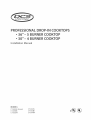
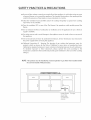
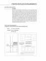
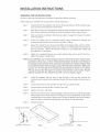
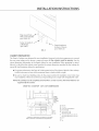
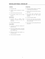
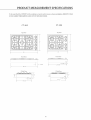
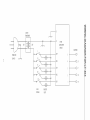
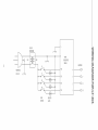
mNCOOKTOPS
• 36"• 30"-
5
URNER
URNER
Mnstallation Manual
MODELS:
CT-365SS (shown)
CT-365BK
CT-365WT
CT-304SS
CT-304BK
CT-304WT
o®®
A MESSAGE TO OUR CUSTOMERS
Thank you for selecting this DCS Professional Drop-ln Cooktop. Because of this appfiance's unique features
we have developed this Installation
Manual.
h° contains valuable information
on how to install your new
appliance for years of safe and enjoyable cooking.
For your convenience, product
questions can be answered by a DCS Customer Care Representative
by
phone: 1-888_281-5698, by emaih support_dcsappliances.com,
orbymaih
Fisher & Paykel Appliances, Inc.
Attention: DCS CustomerCare
5900 Skylab Road
Huntington Beach, CA 92647
www.dcsappliances.com
Z_
WARNING
Improper installation,
property
damage,
maintenance
adjustment
injury
instructions
alteration,
service or maintenance
or death.
Read the installation,
thoroughly
before
use, installing
can cause
operating
and
or servicing
this
equipment.
Z_
WARNING
Do Not store or use gasoline
or any other flammable
vapors and liquids in the
vicinity of this or any other appliance.
FOR YOUR SAFETY
IFYOUSMELLGAS:
1. Do not turn on any electrical switch; do not use any phone in your building.
2. Immediately
catl your gas supplier from a neighbor's
phone.
Follow the gas
supplier's instructions,
3. If you cannot reach your gas supplier, call the fire department.
and service must be performed
gas supplier.
PLEASE RETAIN THIS MANUAL
by a qualified
FOR FUTURE REFERENCE.
installer,
Installation
service agency or the
TABLE OF CONTENTS
SAFETY PRACTICESAND PRECAUTIONS...............................................
PROPERVENTILATION REQUIREMENTS ..................................................
INSTALLATION INSTRUCTIONS ........................................................
Preparing
for the Hnsta[[ation
Cabinet Preparation
...........................................................
...................................................................
Gas Hook Up ..........................................................................
Power Requirements
Recommended
.................................................................
Grounding
Method
....................................................
3-5
6
7-10
7
8
9
10
10
INSTALLER FINAL CHECKLIST............................................................
11
PRODUCT MEASUREMENT SPECIFICATIONS ...........................................
12
WIRING DIAGRAM ....................................................................
SERVICE ...................................................................................
WARRANTY ...........................................................................
13-14
15
16-17
SAFETY PRACTICES & PRECAUTIONS
When properly
app[hnce.
cared for, your new DCS Appliance
When
using
this type app[hnce
precautions
this
provides
must be followed
restaurant
intense
has been designed
caliber
appliance,
heat and can increase
when using kitchen app[hnces,
to be a safe, reliable cooking
use
it
with
the accident
including
extreme
potenthL
care,
Basic safety
the following:
[] Read the Use and Care Manual thoroughly
before using your new app[hnce.This
reduce the risk of fire, eHectdc shock, or injury to persons.
wH[ help to
[] Begin by insuring proper instaHHation and servicing. FoHHowthis instaHHation instructions.
to have a quaHified technician install[ and ground this appliance before using.
[] Have the installer show you where the gas supply shuboffvalve
and where to turn offthe gas to the appliance.
as
Be sure
is located so you will know how
[] If you smell gas, the installer has not done a proper job of checking for leaks.You can have a
small leak and therefore a faint gas smell if the connections are not completely sealed. Finding
a gas leak is not a "do-it-yourself"
procedure. Some leaks can only be found with the burner
control in the ON position and for your protection
it must be done by a qualified service
technician.
If by some chance a burner goes out and does not re-ignite and gas escapes, open a window or
a door to let the room air out, Do not attempt to use the appliance until the gas has had time to
dissipate,
[]
This appliance has been factory assembled
model number,
[]
Do not repair or replace any part of this appliance unless it is specifically recommended
manual A[[ other servicing should be referred to a qualified service technician.
Z_
for Natural
Gas or Liquid
Propane as indicated
by
in this
WARNING:
CHILDREN SHOULD NOT BE LEFT ALONE or unattended
appliances
are in use. They should
never be allowed
in an area where
to turn
knobs, push
buttons, sit or stand on any part of an appliance.
Z_
WARNING:
Do not store items of interest to children on or around
the Dropoln Cooktop.
Children could be seriously injured if they should climb onto or reach across the
appliance
to reach these items.
[]
Never store anything on the cooktop. Flammable materials can accident[y
items may melt or ignite and other types of items could be ruined,
catch fire, plastic
[]
Do not hang articles from any part of the appliance, Some fabrics are quite flammable
catch on fire,
[]
If the appliance is near a window be certain the curtains do not Now over or near the cooktop
burners; they could catch on fire,
[]
Never let clothing, pot holders, or other flammable materials come in contact with, or too close
to any burner or burner grate until it has cooled, Fabric may ignite and result in personal iniury,
and may
SAFETY PRACTICES & PRECAUTIONS
[] Be certain to use only dry pot holders; moist or damp pot holders on hot surfaces may cause
burn injury from steam. Do not use a towel or other bulky cloth in place of pot holders. Do not
let pot holders touch hot burners, or burner grates.
[] For persona[ safety, wear proper apparel Loose fitting garments or hanging sleeves should
never be worn while using this applhnce. Some synthetic fabrics are highly flammable and
should not be worn while cooking.
[] Do not use aluminum
fire hazard.
Z_
foil to line any part of the cooktop.
Using a foil liner could result in a
WARNING:
This appliance
is for cooking.
Based on safety considerations,
never use the
cooktop to warm or heat a room.
Z_
WARNING:
When using the cooktop:
surrounding
cause
Do not touch the burner grates or the immediate
area. Areas adjacent
to the burners may become hot enough
to
burns.
[] Never leave the cooktop unattended
when using high flame settings. A possible boil over
could cause smoking or greasy spH[ overs may ignite. More importantly, if the burner flames are
smothered by a severe boil over which effects the igniter, the unburned
gas will escape into
the room, which would be extremely dangerous.
[] Only certain types of glass, heat-proof glass-ceramic, ceramic, earthen ware, or other glazed
utensils are suitable for use on the open flame of the cooktop. Utensils that are not thermally
heat safe may break with sudden temperature changes.
[] Do not heat unopened
food containers; a build up of pressure may cause the container
to burst.
[] During cooking, set the burner control so that the flame heats at the bottom of the pan and
does not curl around the bottom edges of the pan.This could heat and/or melt the handles.
[] Always use utensils that have fiat bottoms large enough to cover the burner. The use of
undersized utensils wiii expose a portion of the flame to direct contact and may result in
ignition of clothing.
[] To minimize burns, ignition of fiammabie materials and accidental spill overs, position handles
of utensils inward so they do not extend over adjacent work a teas, cooking areas, or the outside
edges of the cooktop.
[] Hold the handle of the pan to prevent movement
of the utensil when stirring
or turning
food.
[] Grease is flammable. Do not use water on grease fires.Turn OFF the burner, then smother the
fire with baking soda or use a dry chemical or foam-type fire extinguisher. Let hot grease cool
before attempting
to handle it. Avoid letting grease deposits collect around the base of the
cooktop burners.Clean after each use or boil over.
[] Use splatter screens over pans when frying foods to minimize
not to use a flame that is too high.
[] For proper lighting
and performance
of the cooktop
possible grease burns. Be sure
burners, keep the burner
ports clean. It
may be necessary to clean these when there is a boil over or when the burner does not light,
even though the electronic igniters click.
[] Clean the cooktop with caution. Avoid steam burns; do not use a wet sponge or cloth to clean
the cooktop while it is hot. Some cleaners produce noxious fumes if applied to a hot surface.
Follow directions provided by the cleaner manufacturer.
SAFETY PRACTICES & PRECAUTIONS
Be sure a[[ the cooktop controls are turned off and the appliance is coo[ before using any type
of aerosoH cHeaner on or around the appHhnce,The chemicaH that produces the spraying action
couHd, in the presence of heat, ignite or cause metaH parts to corrode,
l
CHean the ventilator hood and fiHters above
vapor does not accumuHate,
l
Turn the ventiHator OFF in case of fire, The blower, if in operation,
flames,
l
Do not obstruct the flow of combustion
suppHy is avaHabHe,
l
For safety reasons and to avoid damage to the appHiance never sit, stand, or Hearton any part of
the appHhnce,
l
Service shouHd onHy be done by authorized technicians,
the power supply before servicing this appliance,
l
California Proposition 65 - Warning: The burning of gas cooking fuel generates some byproducts which are known by the State of California to cause cancer or reproductive
harm,
California law requires businesses to warn customers of potential exposure to such substances,
To minimize exposure
to these substances, always operate this unit according
to the
instructions contained in this booklet and provide good ventilation to the room when cooking
with gas,
NOTE: This product
the cooktop
frequentHy so grease from cooking
couHd unsafeHy spread the
or ventiHation air to the appHiance, Be sure a fresh air
Service technicians
must be instMled by a ficensed p/umber
the CommonweMth
of Massachusetts,
must disconnect
or gas fitter when instMled
I
Installer supplied
shut-offvalve
must be easily
accessible inside
cabinetry.
\
Gas Supply
within
PROPERVENTILATION REQUIREMENTS
IMPORTANT INFORMATION:
CAUTION:
Ventilation
Howeverl
hoods and blowers are designed
some local building
ducting. Consult local building
ensure
that
hood
blower
speeds should
conditioned
and
duct
codes and/or
installation
be variable
household
for use with single wall ducting.
codes or inspectors
may require
double
local agencies before starting,
will meet
local
requirements.
ventilation
to
Hood
to reduce noise and loss of heated
air when maximum
wall
or air
is not required. For best
smoke
efimination,
the lower edge of the hood should
BE INSTALLED A
MINIMUM OF 30" TO A MAXIMUM OF 36"ABOVE THE COOKING SURFACE. If the
hood
contains
minimum
any combustible
materials
of 36" above the cooking
air, a source
of outside
(i.e. a wood
surface.
replacement
covering)
air is recommended.
important
for tightly
sealed
and insulated
ventilating
contractor
should
be consulted.
it must
Due to a high volume
homes.
be a
of ventilation
This is particularly
A reputable
heating
and
VENTILATION REQUIREMENTS:
STANDARD COUNTER INSTALLATION RECOMMENDATIONS
HOOD:
BLOWER:
(24" Deep x Unit Width)
30"/36"
COOKTOPS
600 CFM rain.
u0
5"
rain.to
combustible
surface -,O_-/
8" Min. clearance to
combustible surface
from side of cooktop
outer edge
ii
i
i
i
i
i
i
i
i
i
i
i
i
i
U
30" Min. clearance to
non-combustible surface,
36" Min. clearance to
combustible surface - from
cooktop cooking surface
0 ii0
A As defined
The
in t he"Natiortafi
hoL'Jzonta[
countertop
surfaces
Fuel
of the
Gas Code"(ANSI
range
top
(cool<top)
Z223
trim
1, [astest
must
not
edition)
be below
level
NOTE: See manufacture%
recomn-_endatiol_s
for ducting
specifications
INSTALLATION INSTRUCTIONS
PREPARING FOR THE INSTALLATION:
Be sure to read page 6 for the proper ventilation
requirements
When making your CUTOUT refer to page 8-9 for cabinet
before you begin.
preparation.
Step 1:
Unpack the unit, the regulator, and remove a[[ packing
and caps. Remove the grates from their boxes.
Step 2:
With the necessary tooHs and hardware ready, measure the distance from the back and
sides of the countertop and cabinet to locate the position of the cooktop Cutout.
Step 3:
Make your Cutout according
to the countertop.
Step 4:
Lower the cooktop into the countertop
cutout, being carefu[
counter, inHet pipe threads, or the power cord of the cooktop.
Step 5:
Square the cooktop to the cutout and install[ the (4) retaining brackets onto the 8 holies
for CT-365 and (2) retaining brackets onto 4 holies for CT-304 [ocated at the bottom of
the unit (See Figure 1 bellow), ff hoHd down brackets are not instaHHed,the cooktop wH[
not pull[ down to countertop.
Step 6:
Tighten the 4 preHoaded thumb screws which wH[ keep the unit secured. Do Not Overtighten (See Figure 2 detail below).
NOTE: Some installations
to the dimensions
may not have adequate
a[[ the burners, rings,
given on page 8 & 9. Square the cutout
not to damage
the
clearance at the front for the "Z'-shaped retain-
ing bracket. In those cases, use the "E-bracket provided.
the cooktop
between
Fasten the bracket to the bottom
chassis using one of the screw holes provided
for the retaining
of
brackets. Make
sure the bracket extends out far enough to con tact the inside of the cabinet face. While pushing down on
the front edge of the cooktop
from above, attach
the bracket to the cabinet.
This step wil insure that the edge of the cooktop is flush with the counter surface. Plug the
adjacent
Step 7:
unused hole in the cooktop
chassis with a screw See Figure 3, page 8.
Install the regulator with the arrow in the direction of the gas flow (towards the
cooktop) using a sealant on the male pipe threads. Put burner rings and burner caps in
place.
Step 8:
Connect the gas line to the unit. Refer to page 9 for gas supply hookup.
Step 9:
Turn bah valve to let the gas flow. Check for gas leak.
Step 10:
Hug the unit into a wail outlet.
Step 11:
Turn the front burner knob on first and apply a match to the burner until the gas lights,
being cautious not to burn your hand or other parts of your body.When the gas is first
activated, there is air present in the gas lines.The match applied to the burner makes it
easier and safer to dear the air/gas mixture. Use Caution to avoid burn injury.
Step 12:
Put grates in place.
Bracket (p/n 91164)
["[
,..L:'-.,
Screw (p/n 15117-02)
F/G_ 1
Screw (p/n 15001-22)
FIG_2
INSTALLATION INSTRUCTIONS
Hug unused hoHe /
with screw included.
(p/n 15001-22)
Fasten to inside of
cabinet face.
....
A
Fasten bracket to
(p/n 91807)
bottom
FIG. 3
CABINET
PREPARATION
The Dropdn Cooktop
the raw cutout
cutout
of chassis.
(p/n 15001-22)
was designed
for easy installation.
However, for the best appearance, to concea]
edges and to ensure a snug and secure fit, the cutouts
dimension
information
in the figures
htion, it is critical that the cabinet
a good fit. See illustrations
cutout
bellow for your installation.
matches the cutout dimensions
must
be precise.
When preparing
provided
Use the
for instaH-
for the cooktop for
below for specifications.
I
For proper performance, the Dropdn Cooktop must be level.To achieve a flush fit of the cooktop,
it will be necessary to have a flat countertop
(front to back and left to right).
I
Be sure to check local building codes for the proper method of installation. Local codes may
vary. Installation, electrical connections, and grounding must comply with all applicable codes.
NOTE: The cooktop
supported
must be completely
removed from
cut-out
to service. The lower firebox is not
by the counter.
DROPdN COOKTOP CUT-OUT DIMENSIONS
A)
B)
C)
D)
E)
18" min.
13" max.
S" rain.to combustiblesA
19-3/4" depth
34-3/4"for CT-365
28-5/8" for CT-304
F) 36" hood width rain. for CT-365
30" hood width rain. for CT-304
:As defined in the"Nati0nal Fuel GasC0de"(ANSI Z22a1, latest edition),
NOTE:Seemanufacturer's recommendations f0r ducting specificati0ns,
G) 2-1/2"
H) S"
I) 18"
INSTALLATION INSTRUCTIONS
DROPdN
(when
installing
COOKTOP
with a DCS DD36
CUT-OUT
or DD30
DIMENSIONS
Downdraft
Ventihtion
System)
18"min.
13" max.
5" rain. to combustiblesA
D} 19-3/4" depth
E) 34-3/4"width
for CT-36S
28-5/8" width for CT-304
F) 33q/2"width
for DD36
27-1/2" width for DD30
G)
H)
I)
J)
As definedinthe"NationalFuelGasCode"(ANSIZ223.1,latestedition).
NOTE:
Seemanufacturer's
recommendations
for ductingspecifications.
NOTE:
Wheninstallinga 30"Co@top
vdtha Downdraft(DDa0Ss),a minimumof
a26" cabinetrydepthisrequired.
GAS HOOK
Supply:
K) Min. 36"for CT-365
Min. 30" for CT-304
UP:
Pressure Hnches W.C.:
1.0_q 4.0"-LPG/d.O_9.0'tNaturaH
Verify the type of gas suppHied to the bcafion.The
Gas or LP (propane),
compatible
with
to dealer
if the unit
depending
on the
be made
model
site before
is not set for site gas supply.
sure the gas supply is turned
should
cooktop
specific
the gas at the installation
appliance, in an accessible location
connections
ordinances.
1/2" min.
2-1/2"
9"
26-1/2"
Gas
is shipped from the factory set for NaturaH
ordered.
proceeding
technician
_/
further.
of shutting
off at the wall valve before connecting
Locate Gas Supply and Electrical Supply. referring
that
the cooktop
Return
and
to the
off the gas supply. Make
the appliance. The gas supply
in accordance
to the illustrations
is
cooktop
A manual valve must be installed external
from the front for the purpose
by a qualified
Verify
below.
Flex Line to Cooktop
with
local codes
or
INSTALLATION INSTRUCTIONS
GAS CONNECTHON FOR CT-365
GAS CONNECTHON FOR CT-304
COUNTERTOP
COUNTERTOP
Required
Power
when
unit
is h_stal]ed
over
Wall
Oven
Requirements:
120 VAC, 60 Hz., singHe phase.
CT-304/CT-365:0.10
Amp. Max.
(Use 15 Amp.circuit
minimum)
I
AHways disconnect
service disconnect
I
Observe all]governing codes and ordinances when grounding,
Nationa] EHectrica] Code ANSI/NFPA No. 70-1990.
Recommended
This appliance
polarized
Grounding
is factory equipped
polarized
responsibility
grounded
ordinances
replacement
and
by a qualified
in the absence of which,observe
with a power supply cord with a three-prong
into a mating grounding-type
120 Volt circuit. If the circuit
and obligation
eHectricity at the
Method:
parallel blades). It must be plugged
a correctly
properly
the eHectric suppHy cord from the wall] outlier or turn off:he
before servicing this appHhnce.
of the installer
polarized
electrician.
shall be in accordance
does not have a grounding
or user to have the existing
receptacle
in accordance
with
with the National
120 volt, 60 Hz single phase, 15 AMP circuit.The
power
plug (with
receptacle
all applicable
changed
local codes
electrical
and
PRONG
supply must be a
must be a NEMA 5q5R device to
with the unit.
_THIRD GROUND PRONG
10
to a
the receptacle
Electrical Code. THE THIRD GROUND
receptacle
to
type receptacle, it is the
In the absence of local codes and ordinances,
SHOULD NOT, UNDER ANY CIRCUMSTANCES, BE CUT OR REMOVED.The
accept the three prong plug supplied
grounding
receptacle, connected
INSTALLER FINAL CHECKLIST
GENERAL
OPERATION:
Placement
of U nit.
All internal
packing
materials
i.e. below grates, around
Specified
surfaces.
clearance
maintained
are removed,
knobs, etc.
to cabinet
Bezels centered on burner knobs and knobs
turn freely.
Unit Leve[- front to back, side to side.
Each
A[[ packaging
removed.
materh[
and
tie
straps
and
Low flame operation
with
15
protection
is provided
con nection.
Adequate
individually
lights
satisfactorily,
with
other
both
burners
operating.
ELECTRICAL:
ReceptacHe
burner
ground
ampere
for
service
circuit
cord
connection.
GAS SUPPLY:
Connection: 1/2 NPT with a minimum
diameter flex [ine.
5/8"
The pressure reguHator which is connected
to the manifoHd is set for 4.0"W.C. for Natural
Gas or lO"W.C.for
LR
Manual gas shut-off
accessible location.
valve
installed
in an
Unit tested and free of gas leaks.
11
A[[ burner
verified,
caps, burner
rings and
burner
bases correctly seated in position,
do not rock or slide,
[eve[, and
Burner grates correctly
do not rock,
[eve[, and
positioned,
PRODUCT MEASUREMENT SPECIFICATIONS
To be sure that the CUTOUT for the cooktop is correct and to insure a dean installation,
8 FOR CABHNETPREPARATION AND CUTOUT SPECIFICATIONS,
CT-365
CT-304
Top View
-_ i£/
I'
Top View
\S _'
io
REFERTO PAGE
@
@
21"
21"
J_
30"
Front View
Front View
i!!:y
¸
_1
•
_
28-5/16"
2-3/4"
2-11/16"_
34-1/2"
R Side View
R Side View
4"
12
-_
B
m
Z
TRANSFORMER
A
230V
)
I20V
)______._
5POINT
GAS
RE4GNITER
MODULE
B
ELECTRODES
C
POWER
CORD
SW5
Oc
SW4
O
SW3
C) LF
)
120VACIN F
LR
)
RR
)
SW2
O RR
SWl
O RF
)
VALVE
SWITCHES
INDICATOR
LIGHTS
©
¢h
,,,,q
|
I20/230V
TRANSFORMER
B
m
A
230V
4POINT
GASRE-IGNITER
MODULE
ELECTRODES
LR
_gW
I20VACIN
b-
SW4
4
0 LR
SW3
3
0
LF
SW2
2
O
RF
SWl
O RR
B
g
O
¢h
,,,,q
|
VALVE
INDICATOR
SWITCHES
UGHTS
O
HOW TO OBTAIN SERVICE:
For warranty
service, contact
please have the following
[] Mode[ Number
[] Serial Number
DCS Customer
information
Care Representative
at (888) 281_5698, Before you ca[[,
ready:
(located at the bottom
([ocated at the bottom
of chassis, right corner)
of chassis, right corner)
[] Date of installation
[] A brief description
Your satisfaction
of the probHem
is of the utmost importance
to us. ffa probHem cannot be resoHved to your satisfaction,
please write to Customer Care or emai[: support_dcsapp[iances,com
Write:
Fisher & Paykel Appliances, Inc,
Attention:
DCS Customer Care
5900 Skylab Road
Huntington
Beach, CA 92647
BEFORE YOU CALL FOR SERVICE:
1, Is the circuit
breaker tripped?
2, Is the gas turned
3, Is the AC plugged
on?
in?
4, Is the burner cap in position?
5,Can the burner be lit with a match?
6, Is the gas type correct for the unit - LP or Natural?
the model # has"L"which stands for LR)
15
(Assume the gas type is natural unless
LENGTH OF WARRANTY
One (1) Year Full parts and Labor covers
Five (5)Years Limited
stainless
steel
the entire
main
tops
product.
(parts
only).
DCS WILL COVER:
AH[repair [abor and parts found to be defective
HOME" warranty
norma[
from date of purchase.
due to materiaHs or workmanship
househoHd use. Service must be provided
working
for one full[ year"IN
This does not appHy if the unit was subjected
by Authorized
Factory Technician
to other than
during
norma[
hours. No charges will[ be made for repair or repHacement at the [ocation of inifia[ instaHHation
or factory for parts returned
pre-paid, through
the dealer and claimed
within the warranty
period, and
found by DCS to be defective.
Replacement
will be F.O.B. DCS, and DCS will not be liable for any transportation
export duties. This warranty
shah not apply, nor can we assume responsibility
result from failure to follow
manufactures
tampered
negligence,
with
or altered
in anyway
instructions
or which,
or local codes, where
in our judgement,
costs, labor costs, or
for damage
that might
the appliance
has been subjected
has been
to misuse,
or accident.
DCS WILL NOT COVER:
[] hsta[[ation
or start-up.
[] Normal adjustment
to burners, gas regulators,
[] Cleaning of igniters and/or
[] Shipping
etc.
genera[ maintenance.
damage.
[] Service by an unauthorized
agency.
[] Damage or repairs due to service by an unauthorized
[] Service during other than normal working
[] Improper
installation,
such as improper
[] Chipping
of porcelain
enamel grates.
agency or the use of unauthorized
hours.
hook-up, etc.
[] Service visits to teach you how to use the appliance;
breakers or replace home fuses.
[] Repairs due to other than normal
parts.
household
correct
the installation;
reset circuit
use.
[] Damage caused from accident, abuse, alteration,
in accordance with local codes.
misuse, incorrect
installation
or installation
not
[] Units installed in non-residential application such as day care centers, bed and breakfast centers,
churches, nursing homes, restaurants, hotels, schools, etc.
This warranty
in commercial
applies to appliances
situations.
This warranty
is for products
Columbia
continues
purchased
and Canada. This warranty
Should the appliance
used in indoor residential
and retained
until the expiration
purchaser
it does not cover their use
in the 50 states of the U.S.A., the District
applies even if you should
be sold by the original
to be protected
applications;
during
date of the original
16
move during
the warranty
the warranty
of
period.
period, the new owner
purchaser's warranty
period.
This warranty
including
is in lieu of all other
warranties
the full extent permitted
duration
particular
of any implied
by law.
warranties,
purpose, are limited
specific legal rights.
warranties,
of merchantability
expressed
or implied,
and fitness for a particular
To the extent
including
to the duration
that implied
implied
and
warranties
warranties
all implied
may not be disclaimed,
of merchantabifl
of this expressed warranty.
to
the
W and fitness for a
This warranty
You may also have other rights which vary from state to state.
17
warranties,
purpose, are hereby disclaimed
gives you
18
A Fisher
& Payk_,l Appliances,
/nc
Company
Fisher & Paykel Appliances, Inc.
5900 Skylab Road, Huntington Beach, CA 92647
Customer Care: 888.28"1.5698
Fax: 714.372.7003
www.dcsappFiances.com
As product improvement
is an ongoing process at DCS, we reserve
the right to change specifications
or design without
notice.
DCS am@liore constamment
modifier
les spetcifications
aucun pr_avis.
Part No. W736 Rev.D
Litho in USA 02/2005
ses produits
et se r_serve le droit de
ou la conception
de ses produits
sans


![議事録[PDF:299KB]](http://vs1.manualzilla.com/store/data/006615021_2-ca7646eafef05d2c88ccbd96aa1a3bbf-150x150.png)