1
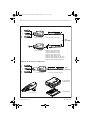
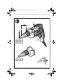
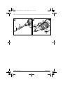
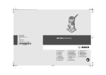
OBJ_DOKU-2243-006.fm Page 1 Monday, March 21, 2011 10:49 AM Robert Bosch GmbH Power Tools Division 70745 Leinfelden-Echterdingen Germany www.bosch-pt.com 2 609 932 794 (2011.03) O / 120 UNI GSR Professional 6-25 TE | 6-45 TE | 6-60 TE de en fr es pt it nl Originalbetriebsanleitung Original instructions Notice originale Manual original Manual original Istruzioni originali Oorspronkelijke gebruiksaanwijzing da Original brugsanvisning sv Bruksanvisning i original no Original driftsinstruks fi Alkuperäiset ohjeet el tr pl cs sk hu ru Ðñùôüôõðï ïäçãéþí ÷ñÞóçò Orijinal işletme talimat Instrukcja oryginalna Původní návod k používání Pôvodný návod na použitie Eredeti használati utasítás Îðèãèíàëüíîå ðóêîâîäñòâî ïî ýêñïëóàòàöèè uk Îðèã³íàëüíà ³íñòðóêö³ÿ ç åêñïëóàòàö³¿ ro Instrucţiuni originale bg Îðèãèíàëíà èíñòðóêöèÿ sr sl hr et lv lt ar fa Originalno uputstvo za rad Izvirna navodila Originalne upute za rad Algupärane kasutusjuhend Instrukcijas oriģinālvalodā Originali instrukcija ΔϴϠλϷ ϞϴϐθΘϟ ΕΎϤϴϠόΗ ̶Ϡλ έΎ̯ ίήσ ̵ΎϤϨϫέ OBJ_BUCH-137-006.book Page 3 Monday, March 21, 2011 10:51 AM 3| GSR 6-25 TE a 2 607 002 586 2 607 002 584 (a=57 mm) 1/4" (6,35 mm) a b 2 607 002 586 2 2 2 2 2 2 2 2 608 608 608 608 608 608 608 608 550 550 550 550 550 550 550 550 557 558 559 560 561 562 563 564 (b=5,5 mm) (b=6,0 mm) (b=7,0 mm) (b=8,0 mm) (b=10,0 mm) (b=1/4" [6,35 mm]) (b=5/16" [8 mm]) (b=3/8" [9,5 mm]) GSR 6-25 TE / GSR 6-45 TE / GSR 6-60 TE a 1/4" (6,35 mm) 2 607 002 585 2 607 001 157 (a=75 mm) 2 608 438 692 (L-BOXX 136) 2 608 438 060 1 600 Z00 00Y 2 609 932 794 | (21.3.11) Bosch Power Tools OBJ_BUCH-137-006.book Page 4 Monday, March 21, 2011 10:51 AM 4| 5 4 3 2 1 GSR 6-45 TE GSR 6-60 TE Professional GSR 6-25 TE Professional 2 609 932 794 | (21.3.11) 8 7 6 9 Bosch Power Tools OBJ_BUCH-137-006.book Page 5 Monday, March 21, 2011 10:51 AM 5| A B 3 10 1 2 609 932 794 | (21.3.11) Bosch Power Tools OBJ_BUCH-137-006.book Page 10 Monday, March 21, 2011 10:51 AM 10 | English Schweiz Tel.: +41 (044) 8 47 15 11 Fax: +41 (044) 8 47 15 51 Luxemburg Tel.: +32 (070) 22 55 65 Fax: +32 (070) 22 55 75 E-Mail: outillage.gereedschap@be.bosch.com Entsorgung Elektrowerkzeuge, Zubehör und Verpackungen sollen einer umweltgerechten Wiederverwertung zugeführt werden. Werfen Sie Elektrowerkzeuge nicht in den Hausmüll! Nur für EU-Länder: Gemäß der Europäischen Richtlinie 2002/96/EG über Elektro- und ElektronikAltgeräte und ihrer Umsetzung in nationales Recht müssen nicht mehr gebrauchsfähige Elektrowerkzeuge getrennt gesammelt und einer umweltgerechten Wiederverwertung zugeführt werden. Änderungen vorbehalten. English Safety Notes General Power Tool Safety Warnings WARNING Read all safety warnings and all instructions. Failure to follow the warnings and instructions may result in electric shock, fire and/or serious injury. Save all warnings and instructions for future reference. The term “power tool” in the warnings refers to your mainsoperated (corded) power tool or battery-operated (cordless) power tool. Work area safety f Keep work area clean and well lit. Cluttered or dark areas invite accidents. f Do not operate power tools in explosive atmospheres, such as in the presence of flammable liquids, gases or dust. Power tools create sparks which may ignite the dust or fumes. f Keep children and bystanders away while operating a power tool. Distractions can cause you to lose control. Electrical safety f Power tool plugs must match the outlet. Never modify the plug in any way. Do not use any adapter plugs with earthed (grounded) power tools. Unmodified plugs and matching outlets will reduce risk of electric shock. f Avoid body contact with earthed or grounded surfaces, such as pipes, radiators, ranges and refrigerators. 2 609 932 794 | (21.3.11) There is an increased risk of electric shock if your body is earthed or grounded. f Do not expose power tools to rain or wet conditions. Water entering a power tool will increase the risk of electric shock. f Do not abuse the cord. Never use the cord for carrying, pulling or unplugging the power tool. Keep cord away from heat, oil, sharp edges and moving parts. Damaged or entangled cords increase the risk of electric shock. f When operating a power tool outdoors, use an extension cord suitable for outdoor use. Use of a cord suitable for outdoor use reduces the risk of electric shock. f If operating a power tool in a damp location is unavoidable, use a residual current device (RCD) protected supply. Use of an RCD reduces the risk of electric shock. Personal safety f Stay alert, watch what you are doing and use common sense when operating a power tool. Do not use a power tool while you are tired or under the influence of drugs, alcohol or medication. A moment of inattention while operating power tools may result in serious personal injury. f Use personal protective equipment. Always wear eye protection. Protective equipment such as dust mask, non-skid safety shoes, hard hat, or hearing protection used for appropriate conditions will reduce personal injuries. f Prevent unintentional starting. Ensure the switch is in the off-position before connecting to power source and/or battery pack, picking up or carrying the tool. Carrying power tools with your finger on the switch or energising power tools that have the switch on invites accidents. f Remove any adjusting key or wrench before turning the power tool on. A wrench or a key left attached to a rotating part of the power tool may result in personal injury. f Do not overreach. Keep proper footing and balance at all times. This enables better control of the power tool in unexpected situations. f Dress properly. Do not wear loose clothing or jewellery. Keep your hair, clothing and gloves away from moving parts. Loose clothes, jewellery or long hair can be caught in moving parts. f If devices are provided for the connection of dust extraction and collection facilities, ensure these are connected and properly used. Use of dust collection can reduce dust-related hazards. Power tool use and care f Do not force the power tool. Use the correct power tool for your application. The correct power tool will do the job better and safer at the rate for which it was designed. f Do not use the power tool if the switch does not turn it on and off. Any power tool that cannot be controlled with the switch is dangerous and must be repaired. f Disconnect the plug from the power source and/or the battery pack from the power tool before making any adjustments, changing accessories, or storing power Bosch Power Tools OBJ_BUCH-137-006.book Page 11 Monday, March 21, 2011 10:51 AM English | 11 tools. Such preventive safety measures reduce the risk of starting the power tool accidentally. f Store idle power tools out of the reach of children and do not allow persons unfamiliar with the power tool or these instructions to operate the power tool. Power tools are dangerous in the hands of untrained users. f Maintain power tools. Check for misalignment or binding of moving parts, breakage of parts and any other condition that may affect the power tool’s operation. If damaged, have the power tool repaired before use. Many accidents are caused by poorly maintained power tools. f Keep cutting tools sharp and clean. Properly maintained cutting tools with sharp cutting edges are less likely to bind and are easier to control. f Use the power tool, accessories and tool bits etc. in accordance with these instructions, taking into account the working conditions and the work to be performed. Use of the power tool for operations different from those intended could result in a hazardous situation. If the plug is not suitable for your socket outlets, it should be cut off and an appropriate plug fitted in its place by an authorised customer service agent. The replacement plug should have the same fuse rating as the original plug. The severed plug must be disposed of to avoid a possible shock hazard and should never be inserted into a mains socket elsewhere. Products sold in AUS and NZ only: Use a residual current device (RCD) with a rated residual current of 30 mA or less. Product Description and Specifications Read all safety warnings and all instructions. Failure to follow the warnings and instructions may result in electric shock, fire and/or serious injury. While reading the operating instructions, unfold the graphics page for the machine and leave it open. Service f Have your power tool serviced by a qualified repair person using only identical replacement parts. This will ensure that the safety of the power tool is maintained. Intended Use Safety Warnings for Screwdriver The numbering of the product features refers to the illustration of the machine on the graphics page. 1 Screwdriver bit* 2 Stop bushing 3 Adjustment sleeve for screwing-depth stop 4 Screwing-depth stop 5 Belt clip 6 Lock-on button for On/Off switch 7 On/Off switch 8 Rotational direction switch 9 Handle (insulated gripping surface) 10 Universal bit holder* f Hold power tool by insulated gripping surfaces, when performing an operation where the fastener may contact hidden wiring or its own cord. Fasteners contacting a “live” wire may make exposed metal parts of the power tool “live” and could give the operator an electric shock. f Hold the machine with a firm grip. High reaction torque can briefly occur while driving in and loosening screws. f Secure the workpiece. A workpiece clamped with clamping devices or in a vice is held more secure than by hand. f Always wait until the machine has come to a complete stop before placing it down. The tool insert can jam and lead to loss of control over the power tool. Products sold in GB only: Your product is fitted with a BS 1363/A approved electric plug with internal fuse (ASTA approved to BS 1362). The machine is intended for driving in and loosening screws. Product Features *Accessories shown or described are not part of the standard delivery scope of the product. A complete overview of accessories can be found in our accessories program. Technical Data Screwdriver Article number GSR 6-25 TE Professional GSR 6-45 TE Professional GSR 6-60 TE Professional 3 601 D45 0.. 3 601 D45 1.. 3 601 D45 2.. 701 Rated power input W 701 701 Output power W 327 327 327 No-load speed min-1 0–2500 0–4500 0–6000 Rated speed min-1 0–1700 0–3000 0–4500 The values given are valid for a nominal voltage [U] of 230 V. For different voltages and models for specific countries, these values can vary. Please observe the article number on the type plate of your machine. The trade names of the individual machines may vary. Bosch Power Tools 2 609 932 794 | (21.3.11) OBJ_BUCH-137-006.book Page 12 Monday, March 21, 2011 10:51 AM 12 | English Screwdriver Tool holder Max. screw dia. Weight according to EPTA-Procedure 01/2003 GSR 6-25 TE Professional GSR 6-45 TE Professional GSR 6-60 TE Professional ¼" hexagon socket ¼" hexagon socket ¼" hexagon socket mm 6 6 6 kg 1.5 1.4 1.4 /II /II /II Protection class The values given are valid for a nominal voltage [U] of 230 V. For different voltages and models for specific countries, these values can vary. Please observe the article number on the type plate of your machine. The trade names of the individual machines may vary. Noise/Vibration Information Measured sound values determined according to EN 60745. Typically the A-weighted noise levels of the product are Sound pressure level Sound power level Uncertainty K= Wear hearing protection! Vibration total values (triax vector sum) determined according to EN 60745: Screwdriving without impact: Vibration emission value ah= Uncertainty K = The vibration emission level given in this information sheet has been measured in accordance with a standardised test given in EN 60745 and may be used to compare one tool with another. It may be used for a preliminary assessment of exposure. The declared vibration emission level represents the main applications of the tool. However if the tool is used for different applications, with different accessories or poorly maintained, the vibration emission may differ. This may significantly increase the exposure level over the total working period. An estimation of the level of exposure to vibration should also take into account the times when the tool is switched off or when it is running but not actually doing the job. This may significantly reduce the exposure level over the total working period. Identify additional safety measures to protect the operator from the effects of vibration such as: maintain the tool and the accessories, keep the hands warm, organisation of work patterns. Declaration of Conformity We declare under our sole responsibility that the product described under “Technical Data” is in conformity with the following standards or standardization documents: EN 60745 according to the provisions of the directives 2004/108/EC, 2006/42/EC. Technical file at: Robert Bosch GmbH, PT/ESC, D-70745 Leinfelden-Echterdingen Dr. Egbert Schneider Dr. Eckerhard Strötgen Senior Vice President Head of Product Engineering Certification Robert Bosch GmbH, Power Tools Division D-70745 Leinfelden-Echterdingen 02.03.2011 2 609 932 794 | (21.3.11) 3 601 ... D45 0.. D45 1.. D45 2.. dB(A) dB(A) dB(A) 81 92 3 79 90 3 81 92 3 m/s2 m/s2 <2.5 1.5 <2.5 1.5 3.3 1.5 Assembly Changing the Tool (see figure A) f Before any work on the machine itself, pull the mains plug. Pull off the screwing-depth stop 4 toward the front. Pull out the screwdriver bit 1. If required, the universal bit holder 10 can also be pulled off and replaced. After changing the tool, reattach the screwing-depth stop 4. Operation Starting Operation f Observe correct mains voltage! The voltage of the power source must agree with the voltage specified on the nameplate of the machine. Power tools marked with 230 V can also be operated with 220 V. Reversing the Rotational Direction The rotational direction switch 8 is used to reverse the rotational direction of the machine. However, this is not possible with the On/Off switch 7 actuated. Right rotation: For driving in screws, push the rotational direction switch 8 left to the stop. Left rotation: Push the rotational direction switch 8 right to the stop (for unscrewing screws). Switching On and Off To start the machine, press the On/Off switch 7 and keep it pressed. To lock the pressed On/Off switch 7, press the lock-on button 6. To switch off the machine, release the On/Off switch 7 or when it is locked with the lock-on button 6, briefly press the On/Off switch 7 and then release it. Bosch Power Tools OBJ_BUCH-137-006.book Page 13 Monday, March 21, 2011 10:51 AM English | 13 Adjusting the Speed The speed of the switched on power tool can be variably adjusted, depending on how far the On/Off switch 7 is pressed. Light pressure on the On/Off switch 7 results in a low rotational speed. Further pressure on the switch results in an increase in speed. Adjusting the Screw-in Depth (see figure B) With the adjustment sleeve 3, the screw-in depth of the screw head into the workpiece can be preset in 8 locking steps per full turn. Each step corresponds with a 0.25 mm change of the screw-in depth. Turning the adjustment sleeve 3 in clockwise direction results in a greater screw-in depth; turning in anticlockwise direction reduces the screw-in depth. The required setting is best determined by testing. Working Advice f Apply the power tool to the screw only when it is switched off. Rotating tool inserts can slip off. Guide the screw toward the screwdriving bit 1. The screw is held in place by the magnet pull of the universal bit holder 10. Firmly push the tip of the screw into the material to be screwed until the screwing-depth stop 4 faces against the workpiece. Switch the machine on. The screw is screwed into the material until the adjusted screw-in depth is reached. The drive is disengaged and the tool holder no longer rotates. Check the screw-in depth and readjust, if required. For unscrewing screws, set the rotational direction switch 8 to left rotation and pull off the screwing-depth stop 4 toward the front without turning the adjustment sleeve. Working with the screwing-depth stop 4 is also possible when adapting the screw-in depth. Belt Clip With the belt clip 5, the machine can be hung onto a belt. The user has both hands free and the machine is always at hand. Maintenance and Service Maintenance and Cleaning f Before any work on the machine itself, pull the mains plug. f For safe and proper working, always keep the machine and ventilation slots clean. If the machine should fail despite the care taken in manufacturing and testing procedures, repair should be carried out by an after-sales service centre for Bosch power tools. In all correspondence and spare parts order, please always include the 10-digit article number given on the type plate of the machine. Bosch Power Tools After-sales Service and Customer Assistance Our after-sales service responds to your questions concerning maintenance and repair of your product as well as spare parts. Exploded views and information on spare parts can also be found under: www.bosch-pt.com Our customer service representatives can answer your questions concerning possible applications and adjustment of products and accessories. Great Britain Robert Bosch Ltd. (B.S.C.) P.O. Box 98 Broadwater Park North Orbital Road Denham Uxbridge UB 9 5HJ Tel. Service: +44 (0844) 736 0109 Fax: +44 (0844) 736 0146 E-Mail: boschservicecentre@bosch.com Ireland Origo Ltd. Unit 23 Magna Drive Magna Business Park City West Dublin 24 Tel. Service: +353 (01) 4 66 67 00 Fax: +353 (01) 4 66 68 88 Australia, New Zealand and Pacific Islands Robert Bosch Australia Pty. Ltd. Power Tools Locked Bag 66 Clayton South VIC 3169 Customer Contact Center Inside Australia: Phone: +61 (01300) 307 044 Fax: +61 (01300) 307 045 Inside New Zealand: Phone: +64 (0800) 543 353 Fax: +64 (0800) 428 570 Outside AU and NZ: Phone: +61 (03) 9541 5555 www.bosch.com.au Republic of South Africa Customer service Hotline: +27 (011) 6 51 96 00 Gauteng – BSC Service Centre 35 Roper Street, New Centre Johannesburg Tel.: +27 (011) 4 93 93 75 Fax: +27 (011) 4 93 01 26 E-Mail: bsctools@icon.co.za 2 609 932 794 | (21.3.11)