1
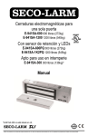
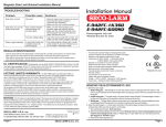
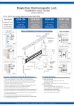
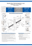
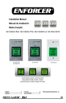
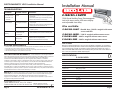
Installation Manual
ELECTROMAGNETIC LOCK Installation Manual
S
ECO-L
RM
SECOLARM
SECO
LAR
TROUBLESHOOTING
Problem:
Possible cause:
Solutions:
• Door does not lock
No power
• Check to make sure the wires are securely tightened to the
terminal block.
• Check that the power supply is connected and operating.
• Make sure the lock switch is wired correctly.
• Status LED is not
illuminated
Door locks, but can be
easily forced open
Poor contact between
electromagnet and armature
plate
• Make sure the electromagnet and armature plate are
properly aligned.
• Make sure the contact surfaces of the electromagnet and
armature plate are clean and free from rust.
Incorrect voltage setting
• Check the power leads with a meter, and make sure 12VDC
or 24VDC is present.
Delay in door
releasing
• A secondary diode was
installed across the
electromagnet
• The electromagnet is fitted with a metal oxide varistor to
prevent interference, so do not install a secondary diode.
No relay output
• No power
• Misalignment
• Check that the power is connected and operating.
• Make sure the lock is aligned properly.
• Make sure the NO/NC/COM are wired properly.
• Check timer
• Make sure timer is adjusted to desired delay time.
Delay in door relocking
REGULAR MAINTENANCE
•
•
•
•
Clean the contact surfaces of the electromagnet or armature plate with a soft cloth and non-abrasive, non-corrosive cleaner.
Apply a light coat of a silicon lubricant to prevent rust. Wipe away the excess.
Check that the armature plate is securely attached to the door, yet can pivot slightly around the armature screw.
Check that the electromagnet is securely attached to the door frame.
LIFETIME LIMITED WARRANTY:
This SECO-LARM product is warranted against defects in
material and workmanship while used in normal service for the lifetime of the product. SECO-LARM’s obligation is limited to the
repair or replacement of any defective part if the unit is returned, transportation prepaid, to SECO-LARM. Under no
circumstances will SECO-LARM be responsible for any costs or charges for removal, installation, or reinstallation.
This Warranty is void if damage is caused by or attributed to acts of God, physical or electrical misuse or abuse, neglect, repair,
or alteration, improper or abnormal usage, or faulty installation, or if for any other reason SECO-LARM determines that such
equipment is not operating properly as a result of causes other than defects in material and workmanship.
The sole obligation of SECO-LARM, and the purchaser’s exclusive remedy, shall be limited to repair or replacement only, at
SECO-LARM’s option. In no event shall SECO-LARM be liable for any special, collateral, incidental, or consequential personal or
property damages of any kind to the purchaser or anyone else. This lifetime limited warranty is for products sold and installed in
the United States and Canada. For all other countries the warranty is 1 (one) year.
NOTICE: The information and specifications printed in this manual are current at the time of publication. However,
the SECO-LARM policy is one of continual development and improvement. For this reason, SECO-LARM reserves the right to
change specifications without notice. SECO-LARM is also not responsible for misprints or typographical errors.
Copyright © 2011 SECO-LARM U S A., Inc. All rights reserved. This material may not be reproduced or copied, in whole or in
part, without the written permission of SECO-LARM.
O A
U
., Inc.
c
SECO-LARM
U.S.A.,
16842 Millikan Avenue, Irvine, CA 92606
Tel: 800-662-0800 / 949-261-2999 Fax: 949-261-7326
Page 4
Website: www.seco-larm.com
E-mail: sales@seco-larm.com
P TGW1
E-941SA-1K2PDc.pmd
SECO-LARM U.S.A., Inc.
E-941SA-1K2PD
1200 Pound Holding Force Electromagnetic
Lock with status sensor, LED status display
and adjustable time delay.
Also available:
E-941DA-1K2P - Double-door 1200 lb. maglock with status
sensor and LED
1200 lb. maglock without status sensor
E-941SA-1200 E-941SA-600 - 600 lb. maglock without status sensor
E-941SA-300 - 300 lb. maglock without status sensor
HOW IT WORKS
When power is applied to the magnetic lock, it turns on the unit's powerful built-in electromagnet. This electromagnet is
attracted to the steel armature plate which is mounted on a door, holding the door fast against unauthorized entry. When
power to the magnetic lock is turned off, the electromagnet releases the armature plate, allowing the door to open. In
addition, the E-941SA-1K2PD has built-in LEDs to show electromagnet status, plus a status sensor to monitor whether the
door is securely closed, and a built-in adjustable-delay locking timer.
SPECIFICATIONS
E-941SA-1K2PD
Power
12/24 VDC
Magnet Size
10½ x 15/8 x 25/8 in. (268 x 42 x 67 mm)
Armature Size
71/4 x 5/8 x 23/8 in. (185 x 16 x 61 mm)
Holding Force
1200-lb (545kg)
Status Sensor
Relay, 3A @ 12VDC
Status LED (2-Color)
Locked - Green, Unlocked - Red
Timer Delay
1~78 seconds
Current Drain
500mA @ 12VDC, 250mA @ 24VDC
Voltage Tolerance
± 10%
Housing
Aluminum
Temperature
14° ~ 131°F (-10° ~ 55°C)
Weight
11-lb (5.0 kg)
Page 1
ELECTROMAGNETIC LOCK Installation Manual
Page 2
D.
E.
F.
G.
H.
SECO-LARM U.S.A., Inc.
For Inswing Doors
Filler
Plate*
Standard
Mounting
* Note: may require more
than one filler plate.
"Z"
Bracket
"L"
Bracket
FIG.
2
FIG. 3: Status
Sensor Output Connect to an alarm
panel or other
monitoring device.
Status Sensor Output — Monitors whether
the protected door is open or closed.
Voltage Selection
12VDC
N.C. — Door opened, red LED on.
Magnet set for 12VDC
operation as supplied
from factory.
N.O. — Door closed, green LED on.
Relay — 3A @ 12VDC.
24VDC
Adjustable Timer Delay — For
1~78 seconds, turn clockwise
to increase time. Timer starts
when power is applied.
E-941SA-1K2PD
SECO-LARM
Position a jumper over
the two middle pins for
24VDC operation.
Status LED*
Timer
Voltage Adjust
Selection
Jumpers
+
Control
Device
Power
Supply
+
Relay
C.
against the door. The plate must be
able to pivot around the armature
screw.
4. Make sure the anti-spin guides are
in the two guidepin holes.
Screw the mounting plate to the door
frame or optional bracket:
1. Screw the two short self-tapping
screws in the slotted holes of the
mounting plate and adjust the
position of the mounting plate so
that it and the armature plate form
a 90-degree angle.
2. Once the position is correct, use the
long self-tapping screws to
permanently mount the bracket.
3. Remove the two short screws.
Drill the cable access hole.
Mount the electromagnet to the door
frame (fig. 1) — Use the Allen
wrench to screw the socket-head
mounting screws through the bottom
of the electromagnet into the
mounting bracket.
Connect the power leads (fig. 3):
1. Open the electromagnet.
2. Run two power leads from the power
supply through the cable access
hole into the electromagnet.
3. Connect the power leads to the
terminal block.
4. Close the electromagnet.
Test the unit.
Insert the tamper caps into the
mounting screw access holes. This
should be the last step, as once the
tamper caps are in place, they will be
difficult to remove.
* Status LED — Indicates
whether the magnetic lock
is locked or unlocked.
Green — Locked
Red — Unlocked
Off — No power
}
A. Drill holes for the mounting plate and
armature plate (see fig. 1 and 2) by
doing the following:
1. Fold the mounting template along
the dotted line.
2. Close the door. Find a mounting
location on the door frame near the
upper free-moving corner of the
door, as close to the corner of the
door frame as possible.
3. Place the template against the door
and frame.
4. Drill two holes in the door frame and
three holes in the door as indicated
on the template.
NOTE — A filler plate or an L-bracket or
Z-bracket (optional) may be required for
the electromagnet, depending on the door
frame. See fig. 1.
B. Mount the armature plate to the door
using at least two steel and one rubber
washer (fig. 2):
NOTE — Actual installation varies
according to door style.
1. Put one rubber washer between two
steel washers, and place them over
the armature screw between the
armature plate and the door. This
will allow the armature plate to
pivot slightly around the armature
screw in order to compensate for
door misalignment.
2. Tighten the sexnut bolt enough so
the armature plate can withstand
the force of someone attempting to
break down the door while the
electromagnet is engaged.
3. Do not tighten the armature plate
FIG.
1
NO
COM
NC
MOUNTING THE E-941SA-1K2PD
ELECTROMAGNETIC LOCK Installation Manual
Status Sensor Output
SPDT rated 3A @ 12VDC
Page 3