1
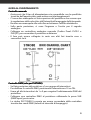
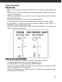
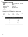
STROBE LIGHT 1500w
PLST15H / PLST15HDX
INDICE
AVVERTENZE ................................................................................................................................................................. 3
CONDIZIONI DI UTILIZZO ........................................................................................................................................ 4
MANUTENZIONE ......................................................................................................................................................... 4
GUIDA AL FUNZIONAMENTO................................................................................................................................. 5
SPECIFICHE TECNICHE............................................................................................................................................... 6
APPENDICE .................................................................................................................................................................... 6
TABLE OF CONTENTS
WARNING NORMS....................................................................................................................................................... 7
OPERATING DETERMINATIONS ............................................................................................................................. 8
MAINTENANCE............................................................................................................................................................. 8
OPERATING MODE...................................................................................................................................................... 9
FEATURES AND SPECIFICATIONS........................................................................................................................10
APPENDIX.....................................................................................................................................................................10
Tutte le specifiche riportate nel presente manuale sono soggette a
variazioni senza preavviso
The specifications related in this manual are subject to modifications
without any advance notice
Rev. 00 – 27/2008
Nel continuo sforzo di migliorare la qualità dei suoi prodotti, la Proel SpA
può introdurre cambiamenti tecnici nel corso della produzione. Pertanto
le specifiche tecniche ed il disegno possono subire variazioni senza
preavviso. La Proel SpA non è responsabile dei danni derivanti da uso
improprio o diverso da quello previsto.
INTRODUZIONE
Per la vostra sicurezza, si prega di leggere questo manuale attentamente
prima di accendere il prodotto.
ISTRUZIONI DI SICUREZZA
Ogni persona coinvolta con l'installazione e la manutenzione di questo
prodotto deve:
- Essere qualificata,
- Seguire le istruzioni di questo manuale.
AVVERTENZE
Prestare molta attenzione durante le ogni operazione. Rischio di scossa
elettrica ad alta tensione quando si presta manutenzione alla macchina.
Questo prodotto ha lasciato la nostra sede in perfette condizioni. Al fine di
mantenere questa condizione e garantire un funzionamento sicuro, è
assolutamente necessario per l'utente seguire le istruzioni di sicurezza
scritte in questo manuale.
IMPORTANTE Il fabbricante non accetta responsabilità per eventuali danni
causati dalla mancata, l’inosservanza di questo manuale o qualsiasi
modifica non autorizzata al prodotto.
Evitare di guardare direttamente
direttamente la luce emessa da l proiettore a distanza
ravvicinata!
Questo prodotto è stato progettato usi interno.
Operare con delicatezza durante l'installazione o il funzionamento.
Al momento di scegliere il posto di installazione, assicurarsi che l'unità non
è esposta a condizioni estreme di calore, umidità o polvere.
Utilizzare l'apparecchio dopo averne verificato la sua integrità.
La temperatura ambiente massima non deve superare i 40 ° C.
Si prega di utilizzare la confezione originale se il prodotto deve essere
trasportato. Modifiche non autorizzate del prodotto sono proibite per
motivi di sicurezza.
3
CONDIZIONI DI UTILIZZO
L'installazione deve essere sempre garantita con un fissaggio secondario
di sicurezza, ad esempio, un apposito cavo.
Durante l’installazione e la disinstallazione, l'operatore deve assicurarsi
delle situazioni di sicurezza dell’impianto e delle macchine.
L'apparecchio deve essere installato al di fuori delle zone dove le persone
possono camminare o essere sedute.
IMPORTANTE! Installazioni sospese richiedono una grande esperienza, tra
cui il calcolo limiti di carico di lavoro, la conoscenza dei materiali destinati
all'installazione, periodica ispezione di tutti i materiali e del proiettore
installato. Se mancano queste qualifiche, non tentare l'installazione.
L’installazione può causare in danni alle persone o cose.
Il dispositivo di fissaggio non deve mai essere fissato oscillare.
Prima di procedere con l’installazione assicurarsi che l’impianto può
reggere un carico di almeno 10 volte il peso del dispositivo di fissaggio.
PERICOLO DI INCENDIO!
Durante l'installazione del dispositivo, assicurarsi che non vi è alcun
materiale altamente infiammabile in una distanza di min. 0.5m.
Installare il dispositivo in una posizione ventilata.
MANUTENZIONE
Evitare di tenere il prodotto in luoghi umidi.
Al fine di mantenere un efficiente sistema di raffreddamento del
proiettore, pulire le superfici esterne del prodotto dalla polvere.
Non usare mai alcol o solventi.
Cambio della lampada
- Prima di cambiare la lampada, assicurarsi di aver scollegato l’unità dalla
tensione di rete.
- Svitare le viti frontali che sostengono la rete di protezione.
- Rimuovere la rete di protezione e poi il vetro.
- Togliere /inserire la lampada molto delicatamente infilando prima un
capo e poi l’altro della lampada evitando di toccarne il bulbo.
- Richiudere il portalampada con il vetro e la rete di protezione
riavvitando le viti sulla parte frontale. Le viti non vanno strette
eccessivamente per evitare di rompere il vetro.
Cambio del fusibile
- prima di cambiare il fusibile, assicurarsi di aver scollegato l’unità dalla
tensione di rete.
- Rimuovere il fusibile bruciato posto all’interno del portafusible.
- Inserire il nuovo fusibile e chiudere il portafusibile.
4
GUIDA AL FUNZIONAMENTO
Controllo manuale
- Assicurarsi che il tipo di alimentazione sia compatibile con le specifiche
tecniche dell’apparecchio onde evitare seri danneggiamenti.
- Ci sono due manopole sul lato superiore del proiettore che servono per
la regolazione della velocità e dell’intensità di lampeggio della lampada.
- Ruotare una manopola alla volta fino ad ottenere l’effetto desiderato.
- Sulla parte posteriore, ci sono l’ingresso e l’uscita per il segnale
analogico.
- Collegare un controllore analogico manuale (Codice Proel: PLCD1 o
PLSQST) per comandare il proiettore a distanza.
- Il faro può essere collegato in serie con altri fari tramite cavo a
connettori Jack.
Controllo DMX (solo per PLSTHDX)
- Sul lato posteriore del proiettore c’è un gruppo di interruttori.
- Per abilitare il controllo DMX, posizionare l’interruttore n.10 su ON.
- Usare gli altri interruttori da 1 a 9 per eseguire l’indirizzamento DMX del
proiettore.
- Collegare una centralina DMX al proiettore utilizzando la presa XLR
(DMX Input) posta retro.
- La strobo PLST15HDX è pronta per essere comandata dalla centralina
tramite due canali DMX (velocità e intensità di lampeggio).
5
SPECIFICHE TECNICHE
Alimentazione
Lampada
Potenza assorbita
Fusibile
Utilizzo
Ingombro
Peso
AC110V /AC230V ±10% 50HZ-60HZ
XOP15
1500W (390 mm)
15A / mm Ø6×30
Uso interno
mm 460x125x220
Kg 3,7
APPENDICE
Questa breve appendice guida all’impostazione dell’indirizzo DMX tramite
gli interruttori posti sul proiettore.
Per fare questo, tenere presente i seguenti valori per ogni singolo
interruttore.
1=1
6 = 32
2=2
7 = 64
3=4
8 = 128
4=8
9 = 256
5 = 16
L’indirizzo DMX è ottenuto dalla somma degli interruttori in posizione ON.
Per esempio:
Valore dell’indirizzo DMX
1
2
3
4
5
7
…
6
Interruttori in posizione ON
1
2
1,2
3
1,3
1, 2 , 3
…
Please note that due to continuous product development, the
specifications are subject to change without notice. Whilst every care is
taken in the preparation of this manual Proel SpA reserves the right to
change specifications in the course of the product improvement. The
publishers cannot be held responsible for the accuracy of the information
here in, or any consequence arising from them.
INTRODUCTION
For your own safety, please read this user manual carefully before you
initial start up.
SAFETY INSTRUCTIONS
Every person involved with installation and maintenance of this product
has to:
- be qualified,
- follow the instructions of this manual.
WARNING NORMS
Be careful with your operations. With a high voltage you can suffer a
dangerous electric shock when touching the wires inside the unit!
This product has left our premises in absolutely perfect condition. In order
to maintain this condition and to ensure a safe operation, it is absolutely
necessary for the user to follow the safety instructions and warning notes
written in this manual.
IMPORTANT
The manufacturer will not accept liability for any resulting damages
caused by the non-observance of this manual or any unauthorized
modification to the product.
Avoid looking directly into the light beam at close range!
This product was designed for indoor use only.
Avoid brute force when installing or operating the unit.
When choosing the installation-spot, please make sure that the unit is not
exposed to extreme heat, moisture or dust.
Only operate the unit after having checked that the housing is firmly
closed and all screws are tightly fastened.
The maximum ambient temperature 40° C must never be exceeded.
Please use the original packaging if the product is to be transported.
Consider that unauthorized modifications on the unit are forbidden due to
safety reasons
7
OPERATING DETERMINATIONS
The installation must always be secured with a secondary safety
attachment, e.g. an appropriate cord . Fasten the safety cord through the
mounting yoke and over the trussing system.
The operator has to make sure the standard of safety-relating and other
machines.
The fixture should be installed outside areas where persons may walk by
or be seated.
IMPORTANT! Overhead rigging requires extensive experience, including
calculating working load limits, installation material being used, and
periodic safety inspection of all installation material and the projector.
Improper installation can result in bodily injury and. or damage to
property. The fixture must never be fixed swinging freely.
Before rigging make sure that the installation area can hold a minimum
point load of 10 times the fixture’s weight.
DANGER OF FIRE !
When installing the device, make sure there is no highly inflammable
material in a distance of min. 0.5m.
Install the device in a ventilated location.
MAINTENANCE
Keep the unit dry.
Periodically clean the frontal panel of the unit with a dry cloth.
Never use alcohol or solvents.
In order to maintain adequate cooling, dust must be cleaned from the
surface.
Replacing the lamp
- Before replacing the lamp, unplug mains lead.
- Unscrew the frontal screws
- Remove the net-brace and lift off the glass.
- Remove/insert the lamp carefully and make sure it is in place securely
avoiding to touch the bulb.
- Replace the glass and the net-brace and screw the brace firmly.
- Do not screw the brace too tightly to avoid the glass can break.
Replacing the
the fuse
- Before replacing the fuse, unplug mains lead.
- Remove the fuse holder on the rear side of the unit.
- Remove the old fuse from the fuse holder.
- Install the new fuse in the fuse holder.
8
OPERATING MODE
Manual mode
- Make sure the power supply is sufficient for the power consumption of
the
- lamps before power up. Otherwise the power lines and the projectors
might be damaged.
- There are two knobs on upside of unit to adjust the speed and the
intensity of flashing.
- Rotate the knobs one by one to set the desired effect.
- On the backside, there are the analogic input and the analogic output.
- Is it possible to connect a remote controller (PROEL Code: PLCD1 or
PLSQST) to the Analogic Input plug.
- The unit can be connected in series with other projectors by means of
cable with Jack connectors.
DMX Mode (only for PLSTHDX)
- On the backside of the projector there is a group in switches.
- To activate the DMX mode, turn the switch no.10 on.
- Use the switches 1-9 to set the desired DMX address.
- Connect a common DMX controller to the projector by using the XLR
Input socket positioned on the rear.
- The PLST15HDX has two DMX channels to adjust the speed and the
intensity and of flashing.
9
FEATURES AND SPECIFICATIONS
Voltage
Lamp
Power consumption
Fuse
Work environment
Packing size
Weight
AC110V /AC230V ±10% 50HZ-60HZ
XOP15
1500W (390 mm)
15A / mm Ø6×30
In-door only
mm 460x125x220
Kg 3,7
APPENDIX
This is a brief guide to DMX dip switch value settings.
DMX Address is set by flipping appropriate DMX dip switches.
To do this, follow the table below:
1=1
6 = 32
2=2
7 = 64
3=4
8 = 128
4=8
9 = 256
5 = 16
The DMX address is the sum of the dip switch values.
For example:
DMX Address Value
1
2
3
4
5
7
…
10
Dip Switches “ON”
1
2
1,2
3
1,3
1, 2 , 3
…
12