1
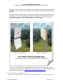
® Canopy OFDM Backhaul Solutions Backhaul Solutions for the Most Challenging Locations and Applications Canopy ® OFDM Backhaul Portfolio 30/60 and 150/300 Mbps Integrated and Connectorized Versions Sales Guide The Canopy OFDM Backhaul Radios are part of Motorola’s Flexible MOTOwi4TM Backhaul Solutions CANOFDMBH-SG-en Issue 4 March 2006 The contents of this Sales Guide are subject to change without notice MOTOROLA, the stylized M Logo and all other trademarks indicated as such herein are trademarks of Motorola, Inc. ® Reg. US Pat & Tm. Office. Canopy is a trademark of Motorola, Inc. All other product or service names are the property of their respective owners. © 2005 Motorola, Inc. All rights reserved Issue 4, March 2005 Page 1 of 30 ® Canopy OFDM Backhaul Solutions Backhaul Solutions for the Most Challenging Locations and Applications The purpose of this document is to equip Motorola account teams and the sales channel with the information needed to communicate the features and benefits of the Motorola OFDM Backhaul Solutions. This is a living document that acts as a central point of reference for all marketing collateral. It is permissible to extract certain sections or subsections that apply to specific customer situations and incorporate them into sales collateral materials. This document should not be used for contracts or proposals in lieu of an official Motorola customer document. Canopy 30/60 and 150/300 Mbps Backhaul - Connectorized1 Canopy 30/60 and 150/300 Mbps Backhaul - Integrated For Public & Private Networks ISP’s, Enterprise, Government, Municipalities, Education and Hospitals We welcome your feedback on Canopy system documentation. This includes feedback on the structure, content, accuracy, or completeness of our documents, and any other comments you have. Please send your comments to technical-documentation@canopywireless.com. 1 Connectorized antennas sold separately from radio. See Page 24 & 27 of this Sales Guide for a complete list of single and dual pole flat panel (1’ – 2’) and parabolic antennas (2’ – 6’) Issue 4, March 2005 Page 2 of 30 ® Canopy OFDM Backhaul Solutions Backhaul Solutions for the Most Challenging Locations and Applications Table of Contents Key Selling Points: ____________________________________________________________ 4 Introduction _________________________________________________________________ 6 Value Proposition_____________________________________________________________ 8 Product Description ___________________________________________________________ 9 Key Technical Features – Canopy OFDM Backhaul Radios _____________________________ 11 Canopy 30/60 Mbps Backhaul Aggregate Ethernet Throughput Rate _____________________ 13 Canopy 150/300 Mbps Backhaul Aggregate Ethernet Throughput Rate ___________________ 14 Competitive Summary ________________________________________________________ 15 OFDM Backhaul Link Estimator Tool ___________________________________________ 16 FAQ ______________________________________________________________________ 18 Ordering ___________________________________________________________________ 21 Appendix A: Technical Specs __________________________________________________ 22 Technical Specs: 30 & 60 Mbps Backhaul Radio – Integrated ___________________________ 22 Technical Specs: 30 & 60 Mbps Backhaul Radio – Connectorized _______________________ 23 Technical Specs: 30 & 60 Mbps Backhaul Radio – Connectorized Antennas _______________ 24 Technical Specs: 150 & 300 Mbps Backhaul Radio – Integrated _________________________ 25 Technical Specs: 150 & 300 Mbps Backhaul Radio – Connectorized _____________________ 26 Technical Specs: 150/300 Mbps Backhaul Radio – Connectorized Antennas _______________ 27 Appendix B: Path Analysis Profile Form _________________________________________ 28 Appendix C: OFDM BH Troubleshooting and RMA Process_________________________ 29 Use this table to aid in interpreting the technical acronyms used throughout this sales guide. BH OFDM QAM LoS nLoS NLoS ODU PIDU DFS PMP PTP PoE Backhaul Radio Orthogonal Frequency Division Multiplexing OFDM is a method of digital modulation in which a signal is split into several narrowband channels at different frequencies. Quadrature Amplitude Modulation QAM is a method of combining two Amplitude-Modulated (AM) signals into a single channel, thereby doubling the effective bandwidth. Line-of-Sight (Clear Line-of-Sight and Fresnel zone is clear) near-Line-of-Sight (Clear Line-of-Sight, but Fresnel zone is blocked) Non-Line-of-Sight (No Line-of-Sight and Fresnel zone is blocked) Outdoor Unit (Integrated or Connectorized Radio) Powered Indoor Unit Dynamic Frequency Selection Point-to-Multipoint Point-to-Point Power over Ethernet Issue 4, March 2005 Page 3 of 30 ® Canopy OFDM Backhaul Solutions Backhaul Solutions for the Most Challenging Locations and Applications Key Selling Points: • Remove System Bottlenecks in the Network with Increased Throughput • Canopy 30 Mbps Backhaul (Software Upgradeable to 60 Mbps BH) o Up to 21 Mpbs - aggregate usable throughput (30 Mbps - Signaling rate) • Canopy 60 Mbps Backhaul o Up to 43 Mbps - aggregate usable throughput (60 Mbps - Signaling rate) • Canopy 150 Mbps Backhaul (software Upgradeable to 300 Mbps BH) o Up to 150 Mbps - aggregate usable throughput • Canopy 300 Mbps Backhaul o Up to 300 Mbps - aggregate usable throughput • Establish Robust Links to Challenging Locations • Single hop long range LoS links – up to 124 miles (200Km) • Previously nearly impossible or marginal links can now be established in: o nLoS – up to 25 miles (40km) o NLoS – up to 6 miles (10km) • Disaster recovery connectivity in a matter of hours • Reduce Capital and Deployment Costs to: • Locations previously inaccessible due to nLoS and NLoS conditions o Reach around buildings, trees, hills and over water o Establish long-range LoS links with a single hop • Meet the growing bandwidth requirements of voice, video and data • Expand video surveillance applications beyond the constraints of existing wired infrastructure • Replace a wired connection with a higher capacity wireless connection that is less expensive • Eliminate Monthly Recurring Costs Associated with Leased T1/E1 Voice Circuits by: • Build-in T1/E1 port o Single port on Canopy 150 Mbps Backhaul o Dual ports on Canopy 300 Mbps Backhaul • Pairing the 30/60/150/300 Mbps Backhaul with a T1/E1 Multiplexer • Reduce Overall Operating Costs • Operators can remotely manage, monitor and optimize link performance via comprehensive web based management • Small form factor reduces the costs of leasing tower space • More links can be co-located without creating excess interference o Narrow 80 antenna beam width – dual polarized antennae o Narrow 12MHz Channel (30/60) and 30MHz Channel (150/300) • Provide Secure Communications • Canopy OFDM BH Solutions utilize a complex proprietary signal with scrambling applied • Deliver High Availability in Noisy and Constantly Changing RF Environments via: A combination of several interference mitigation techniques: • Dynamic Frequency Selection (DFS) automatically changes channels to avoid interference and combat link fading without user intervention • Adaptive Modulation ensure maximum throughput optimized for the radio path even as path characteristics change • Transmit Diversity which transmits two redundant signals spaced in time to bring multi-path signals into phase resulting in better performance and link availability. • Offer Network Design Flexibility • Choose from four platforms, 30/60 or 150/300 Mbps Canopy BH links, available in two versions integrated or connectorized Issue 4, March 2005 Page 4 of 30 ® Canopy OFDM Backhaul Solutions Backhaul Solutions for the Most Challenging Locations and Applications • Migration path to higher bandwidth, Canopy 30 Mbps BH to a Canopy 60 Mbps BH, Canopy 150 Mbps BH to a Canopy 300 Mbps BH • Dual powering options (-48V DC and AC) provide several different power supply configurations such as -48V DC wind or solar power and redundant configurations • Easy Link planning and management • Optimize a link before deployment using the Canopy OFDM BH Link Calculator Tool which simulates a links performance and enables variables to be changed to instantly see the effects on performance Issue 4, March 2005 Page 5 of 30 ® Canopy OFDM Backhaul Solutions Backhaul Solutions for the Most Challenging Locations and Applications Introduction ® Motorola Introduces the Addition of Canopy OFDM Backhaul Solutions To Its MOTOwi4TM Backhaul Portfolio ® Motorola’s Canopy System provides carrier, service provider and enterprise network operators with a robust wireless broadband portfolio of products to deliver proven, cost-effective, secure, carrier-grade broadband access exactly when and where it is needed. The MOTOwi4 Backhaul Portfolio includes two series of Canopy backhaul technology: - The Canopy 10 and 20 Mbps Backhaul Radios - The Canopy 30/60 and 150/300 Mbps Backhaul Radios Both deliver enterprise users, service providers and carriers highly reliable and secure point-to-point wireless backhaul links for bandwidth-intense and latency sensitive applications. The Canopy 10 and 20 Mbps Backhaul Radios are designed for Line-of-Sight (LoS) applications with low latency (under 5ms roundtrip) and high reliability for low cost deployment worldwide in five unlicensed frequencies. (2.4, 5.1, 5.2, 5.4 & 5.7GHz). The Canopy 30/60 & 150/300 Mbps OFDM BH Radios are designed for LoS, nLoS & NLoS applications with low latency (<7ms for 30/60; <1ms for 150/300) and high reliability for deployment worldwide.Canopy 30/60 Mbps Backhual is available in the 5.7GHz and 5.4 GHz unlicensed band. Canopy 150/300 Mbps Backhaul is available in 5.7 GHz unlicensed band.The radios are offered in two versions, with a choice of - Integrated and Connectorized antennas - providing the operator with the flexibility to establish challenging links over water, through trees, over hills and around buildings using the small integrated antenna form factor or by using higher gain flat or parabolic antennas with the Connectorized version. Just like the other Canopy Backhaul solutions, the Canopy 30/60 and 150/300 Mbps OFDM Backhaul solutions are designed to easily deploy in a matter of hours and to operate for years in extreme weather conditions from -40 to +60 C. Each solution in the Canopy Backhaul portfolio offers high carrier-tointerference (C/I) ratio, which enables exceptional performance in high interference environments. The OFDM Backhaul Radios include additional interference mitigation techniques as well - DFS, Adaptive Modulation, Transmit Diversity - improving performance and uptime in challenging nLoS and NLoS applications. By providing a secure, high throughput short-range NLoS or long-range LoS connection, the Canopy system 30/60 or 150/300 Mbps OFDM Backhaul solution provides a wireless alternative to remove network bottlenecks at a fraction of the cost of wire line alternatives. Line-of-Sight Solutions Canopy 10/20 Mbps BH Issue 4, March 2005 Line-of-Sight, near-LoS, Non-LoS Canopy 30/60 and 150/300 Mbps BH Page 6 of 30 ® Canopy OFDM Backhaul Solutions Backhaul Solutions for the Most Challenging Locations and Applications Available in two versions: Integrated Antenna & Connectorized Antenna Canopy Backhaul Portfolio Offers Choice and Flexibility 5 Frequencies for 10 Mbps BH w/DES 5 Frequencies for 10 Mbps BH w/AES 5 Frequencies for 20 Mbps BH w/DES 5 Frequencies for 20 Mbps BH w/AES 2 Frequencies for 30/60 Mbps BH (Integrated/connectorized) 1 Frequency for 150/300 Mbps BH (Integrated/connectorized) 10/20 for LoS Canopy 10/20 Mbps Backhaul Line of Sight (LoS) 30/60 and 150/300 for Challenging LoS, nLoS and NLoS Connectorized Canopy 30/60 Flat Plate or Dish & 150/300 Mbps OR OFDM Backhaul Integrated Antenna Line of Sight near-LoS Non-LoS Canopy Backhaul Applications Deliver high bandwidth to support today’s demanding applications: • Voice over IP • IP gaming • IP video • IP data Backhaul Configuration Examples: • • • • • • • • Interconnecting campus buildings & remote branch offices over right-of-ways Extending T1/E1 PBX circuits Connecting enterprise voice and data Reaching remote Canopy PMP Clusters Temporary and disaster recovery Fiber replacement Backbone for Metro Wi-Fi Networks Backbone for high-bandwidth video surveillance, remote learning and telemedicine Issue 4, March 2005 Page 7 of 30 ® Canopy OFDM Backhaul Solutions Backhaul Solutions for the Most Challenging Locations and Applications Value Proposition The Canopy OFDM Backhaul Solutions deliver unique and exciting opportunities to different markets: Market Opportunity Rural Carriers • Enterprise Network Operators • Urban Carriers • Municipalities/ Education/Healthcare • Grow subscriber networks by establishing service in distant locations with a single backhaul link. Provide high throughput point-to-point links to connect campus buildings to branch offices and other campus buildings that may not be reached cost-effectively with a wired connection. While a wired solution may take weeks to provision, a Canopy wireless solution can be up and running in days and offers more bandwidth for less money. Remove network bottlenecks and eliminate monthly leased wire/fiber connections with a high throughput wireless backhaul that works well in both nLoS and NLoS environments with high interference conditions that are typical in urban settings. Establish cost-effective network backups or extend network reach to aggregate voice, video and data from multiple remote locations without trenching new fiber. The features of the Canopy OFDM Backhaul Solutions deliver real, measurable value to customers: Value Revenue Generation Reduce Costs Reliability & Performance Lower Risk Issue 4, March 2005 Driver Increased nLoS or NLoS and long range LoS enables links to be established to locations previously inaccessible. Increased nLoS, NLoS and long range LoS links reduce the number of hops saving on equipment and associated tower costs. Replace leased T1/E1 voice circuits by pairing a T1/E1 Multiplexer with the 30/60 or by activating the one built-in T1/E1 port in the BH 150 or two built-in T1/E1 ports in the BH 300. The radios small footprint and Power over Ethernet means that operators can deploy in space constrained and aesthetically challenging environments without using up valuable tower space. No Truck Rolls After Installation- each radio features an integrated web server which enables remote management to configure, monitor & upgrade a link via any remote browser. Canopy OFDM Backhauls offer exceptional interference mitigation techniques (DFS, Transmit Diversity & Adaptive Modulation) that provide a reliable network connection in noisy RF environments. As conditions change the radio will automatically change channels (DFS) or modulation “downshift” to maintain a reliable connection without user intervention. A single Ethernet drop cable transports both data and Power over Ethernet. Dual powering options enable both – 48V DC and AC power plus the flexibility to configure the power supply in a stand alone or redundant configuration. OFDM technology combined with Transmit Diversity enables a highly reliable connection in challenging conditions – around buildings, through and over trees, over hills and over water. High capacity throughput enables efficient backhaul connections between business locations or to reach multiple Canopy AP clusters. The 30 Mb BH provides a migration path to 60 Mb BH via a software activation key. The 150 Mb BH provides a migration path to 300 Mb BH via a software activation key. By using the Canopy Link Estimator Tool an operator can simulate link performance before deploying a link. A link can be optimized for the best performance by fine tuning a number of factors to instantly see the effect on link performance. Canopy OFDM Backhauls use a narrow RF channel which enables co-location with Canopy Access Point Clusters, ability to function in crowded and challenged RF environments. Page 8 of 30 ® Canopy OFDM Backhaul Solutions Backhaul Solutions for the Most Challenging Locations and Applications Product Description The Canopy Backhaul portfolio has an array of modules that enable network architects to meet service requirements at the lowest cost. The Canopy 30/60 and 150/300 Mbps OFDM Backhaul Radios complement the Canopy 10/20 Backhaul and Canopy Point to Multipoint (PMP) product line (900MHz, 2.4, 5.2, 5.4 and 5.7 GHz) to allow network operators a variety of solutions so that the network can be tailored to meet specific requirements. Signaling Rate and Range: Canopy 10/20 Mbps Backhaul: Backhaul Radio Frequency Channel Width (roundtrip Latency) 2.4 GHz 10 Mbps 20 MHz 2.4 GHz 20 Mbps 20 MHz 5.2 GHz 10 Mbps 20 MHz 5.2 GHz ER/ 10 Mbps 5.2 GHz ER/ 20 Mbps Aggregate Ethernet Throughput 20 MHz 20 MHz 5.4 GHz 10 Mbps 20 MHz 5.4 GHz 20 Mbps 20 MHz 5.7 GHz 10 Mbps 20 MHz 5.7 GHz 20 Mbps 20 MHz Issue 4, March 2005 7.5 Mbps ( 5.0ms ) 14.0 Mbps ( 5.0ms ) 7.5 Mbps ( 5.0ms ) 7.5 Mbps ( 5.0ms ) 14.0 Mbps ( 5.0ms ) 7.5 Mbps ( 5.0ms ) 14.0 Mbps ( 5.0ms ) 7.5 Mbps ( 5.0ms ) 14.0 Mbps ( 2.5ms ) # NonOverlapping Channels Range w/o Reflector part # 3 (8 km) 2400BH 3 (3.2 km) 2400BH20 3 (3.2 km) 5200BH 3 n/a 10mi (16 km) 5210BHRF 3 n/a 5mi (8 km) 5210BHRF20 3 (3.2 km) 5400BH 3 (1.6km) 5400BH20 3 (3.2 km) 5700BH 3 (1.6 km) 5700BH20 5mi 2mi 2mi 2mi 1mi 2mi 1mi Range w/ Reflector part # 35mi (56 km) 2400BHRF 35mi (56 km) 2400BHRF20 n/a 10mi (16km) 5400BHRF 5mi (8km) 5400BHRF20 35mi (56 km) 5700BHRF 35mi (56 km) 5400BHRF20 Page 9 of 30 ® Canopy OFDM Backhaul Solutions Backhaul Solutions for the Most Challenging Locations and Applications Canopy OFDM Backhaul: Backhaul Radio Frequency Channel Width 5.4/5.7 GHz 30 Mbps* 12 MHz Aggregate Ethernet Throughput (roundtrip Latency) 1.5 Mbps – 21 Mbps # NonOverlapping Channels Range w/o Reflector part # DFS n/a ( < 7.0ms) 5.4/5.7 GHz 60 Mbps* 12 MHz 3.0 Mbps – 43 Mbps DFS n/a DFS n/a DFS n/a ( < 7.0ms) 5.7 GHz 150 Mbps* 30 MHz 7.2 Mbps – 150.1 Mbps (<1.0ms) 5.7 GHz 300 Mbps* 30 MHz 14.4 Mbps – 300.2 Mbps ( < 1.0ms) Range w/ Reflector part # nLoS – up to 6mi (10Km) NLoS – up to 25mi (40Km) LoS – up to 124mi(200Km) bP5430BH20-2 Integrated BP5430BHC20-2 Connectorized BP5730BH20-2 Integrated BP5730BHC20-2 Connectorized nLoS – up to 6mi (10Km) NloS – up to 25mi (40Km) LoS – up to 124mi(200Km) bP5430BH-2 Integrated BP5430BHC-2 Connectorized BP5730BH-2 Integrated BP5730BHC-2 Connectorized nLoS – up to 6mi (10Km) NloS – up to 25mi (40Km) LoS – up to 124mi(200Km) BP5830BH15-2 Integrated BP5830BH15C-2 Connectorized nLoS – up to 6mi (10Km) NLoS – up to 25mi (40Km) LoS – up to 124mi(200Km) BP5830BH-2 Integrated BP5830BHC-2 Connectorized * Data rates are dynamically variable with modulation. Use OFDM BH Link calculator tool to provide accurate link performance estimates. Issue 4, March 2005 Page 10 of 30 ® Canopy OFDM Backhaul Solutions Backhaul Solutions for the Most Challenging Locations and Applications Key Technical Features – Canopy OFDM Backhaul Radios The Canopy 30/60 and 150/300 Mbps OFDM Backhaul Radios use the innovative combination of technologies to deliver unsurpassed range, capacity, reliability and performance – especially in nLoS or NLoS conditions, and in areas where there is a significant RF interference, such as a city. The nLoS and NLoS capabilities provide a higher tolerance for obstructions and enable the network operator to establish network connections over hills, around buildings, through trees and over water. Canopy 30/60 and 150/300 Mbps OFDM Backhaul Radios - Similarities: The 30/60 and 150/300 Mbps OFDM Backhaul Radios share many feature characteristics, including: • Dynamic Frequency Selection (DFS) automatically changes channels to avoid interference and combat link fading without user intervention. At power-up and throughout operation, the radio scans the band — 400 times a second — and automatically switches to the clearest channel. The 25-hour, time-stamped database provides alerts to any interference that does exist and provides statistics to help analyze these patterns. DFS creates “licensed band-like interference-free performance in an unlicensed band!” • Adaptive Modulation ensures maximum throughput optimized for the radio path, even as path characteristics change. The transmitter and receiver negotiate the highest mutually sustainable data rate — then dynamically “upshift” and “downshift” the rate as RF conditions change. • Built-in Security Protection via a complex proprietary signal with scrambling applied. • Dual Polarized Antennas - two transmitters and two receivers are used to establish a link, enabling four different transmitter/receiver combinations. By creating four distinct transmission beams, the chances that data will get through increase significantly. • Transmit Diversity transmits two redundant signals, spaced in time, to bring multi-path signals into phase, resulting in better performance and link availability. The radio radiates multiple beams from the antenna — the effect of which is significant protection against fading and increased probability of making a connection and reading the transmitted data. Alternatively, if this feature is turned off, the radio will operate in Dual Payload mode whereby different data is transmitted in parallel on each signal - effectively doubling the bandwidth at the higher modulation rates. • Orthogonal Frequency Division Multiplexing (OFDM) In addition to Transmit Diversity transmitting the data twice, OFDM sends these transmissions over multiple frequencies, or sub-carriers. The multiple sub-carriers allow higher channel bandwidth & higher resistance to two factors: (1) Multi-path interference - occurs when objects in the air gap split a beam into parts that travel different paths and interfere with each other at the receiver. (2) Frequency selective fading – occurs when amplitudes of arriving signals cancel each other out at the receiver. In typical radios this would be a problem, but with OFDM radios this actually helps as they can recorrelate the interfering signals which results in a better chance of receiving the signal through reflective behavior. • Built-in Security - To ensure a secure connection, each pair of outdoor units comes preset with its own built-in IP address as well as the MAC address of the other outdoor unit to which it will connect. The preset addresses enable the system security features and allow the two units to communicate only with each other. • Physical Form Factor – The 30/60 and 150/300 share the same form factor and are offered with Integrated or Connectorized* antennas. Power Supply** supports -48V DC and AC 48V Cable size is 2.5mm 2 stranded or 14 Awg stranded. Integrated Connectorized* * Connectorized antennas sold separately. See page 30 & 33 for a list of 1-2’ Flat Panels and 2-6’ Parabolic Antennas ** Power Supply is outdoor temperature rated -40°C to +60°C – Requires a weatherproof enclosure when mounting outdoors. Issue 4, March 2005 Page 11 of 30 ® Canopy OFDM Backhaul Solutions Backhaul Solutions for the Most Challenging Locations and Applications Canopy 30/60 and 150/300 Mbps OFDM Backhaul Radios - Differences: The differences between the OFDM Backhaul Radios provide the operator with a selection of choices based on features, bandwidth requirements and price points to cost effectively establish a long range LoS or a challenging nLoS or NLoS wireless link. The OFDM Backhaul radios primary feature differences are: • • • • • • • • Hardware Software - 30/60 and 150/300 use different hardware (electronics) No difference in hardware between 30 Mbps BH and 60 Mbps BH No difference in hardware between 150 Mbps BH and 300 Mbps BH Maximum bandwidth of 30/60 Radios determined by software key; a 30 Mb BH can be easily upgraded to a 60 Mbps BH - Maximum bandwidth of 150/300 Radios determined by software key; a 150 Mb BH can be easily upgraded to a 300 Mbps BH - 30/60 and 150/300 run on entirely different software Power Supply - one key difference between the 30/60 power supply and the 150/300 power supply: - 150/300 Mbps BH PIDU powers the radio over CAT 5e 1000Base-T Gigabit Ethernet - 30/60 Mbps BH PIDU powers the radio over CAT5e 100Base-T Ethernet 30/60 PIDU 150/300 PIDU AC and -48V DC 100Base-T PoE AC and -48V DC 1000Base-T PoE Spectrum - 30/60 Mbps BH uses 12MHz of spectrum - 150/300 Mbps BH uses 30MHz of spectrum. Modulation - 30/60 Mbps BH ranges from BPSK to 64QAM - 150/300 Mbps BH ranges from BPSK to 256QAM T1/E1 Capability - 30/60 Mbps BH must be paired with a T1/E1 Multiplexer; it has a TDM Mode software feature that generates a new set of Adaptive Modulation margins which reduces the probability of codeword errors (and hence packet loss). - 150/300 Mbps BH has built in T1/E1 port in the radio. 150 Mbps BH has one built-in T1/E1 port and 300 Mbps BH has two. The 150/300 Mbps BH can also be paired with a T1/E1 Multiplexer t to transport voice. Fiber Option - The 150/300 Mbps BH has an optional fiber conversion kit (see page 17 for details). WiMAX Spectrum Management Control for 150/300 Mb BH - 30/60 Mb BH includes two Spectrum Management Options - 150/300 Mb BH includes three Spectrum Management Options - Explanation of three options: DFS – Dynamic Frequency Selection continually monitors the 5.7GHz spectrum looking for the channel with the lowest level of on channel and co-channel interference. Fixed Channel – Fixed frequency mode allows the installer to fix transmit and receive frequencies on the radio. WiMAX – WiMAX mode allows the installer to assign WiMAX compatible channelisations. An additional side effect of configuring the WiMAX mode is to enable the WiMAX SNMP MIB support. Issue 4, March 2005 Page 12 of 30 ® Canopy OFDM Backhaul Solutions Backhaul Solutions for the Most Challenging Locations and Applications Canopy 30/60 Mbps Backhaul Aggregate Ethernet Throughput Rate The equipment capability of the 30/60 Mbps Backhaul Radio is given in Tables 1 and 2. These tables provide the Ethernet throughput rate vs. link loss for the Canopy 30/60 Mbps Backhaul in both high throughput and low latency modes. The link loss is the total attenuation of the wireless signal between the two Point-to-Point radios. Adaptive modulation will ensure that the highest throughput that can be achieved instantaneously will be obtained taking account of propagation and interference. When the link has been installed, the Status Page on the management interface provides information about the link loss currently measured by the equipment both instantaneously and averaged. The averaged value will require maximum seasonal fading to be added and then the radio reliability of the link can be computed. Aggregate Ethernet Throughput Rate (Mbps) [1] Hi = High Throughput Mode Lo = Low Latency Mode 0-5km Hi Lo 0-40km Hi 0-100km 0-200km Lo Hi Lo Hi Lo 5.7 GHz Max Path Budget (dB) [2] 5.4 GHz Max Path Budget (dB) [2] 64QAM⅞ 42.5 39.7 39.5 34.7 35.2 28.5 29.8 22 138.1 139.8 64QAM¾ 36.4 34 33.8 29.7 30.2 24.5 25.5 18.9 142.3 142.5 64QAM⅔ 32.4 30.2 30.1 26.4 26.8 21.8 22.7 16.8 144.4 144.3 16QAM¾ 24.3 22.7 22.6 19.8 20.1 16.3 17 12.6 150.4 150.9 16QAM½ 16.2 15.1 15 13.2 13.4 10.9 11.3 8.4 155.2 153.5 QPSK⅔ 10.8 10.1 10 8.81 8.93 7.25 7.56 5.6 160.7 160.3 QPSK½ 8.1 7.55 7.52 6.61 6.7 5.44 5.67 4.2 163 162.8 BPSK½ 3.6 3.36 3.34 2.94 2.98 2.42 2.52 1.87 168.5 168.6 5.7 GHz Max Path Budget [2] (dB) 5.4 GHz Max Path Budget [2] (dB) Table 1: Canopy 60 Mbps Backhaul Aggregate Ethernet Throughput Rate (Mbps) [1] Hi = High Throughput Mode Lo = Low Latency Mode 0-5km Hi Lo 0-40km 0-100km 0-200km Hi Lo Hi Lo Hi Lo 64QAM⅞ 21.3 19.8 19.7 17.3 17.6 14.3 14.9 11.0 138.1 139.8 64QAM¾ 18.2 17.0 16.9 14.9 15.1 12.2 12.8 9.4 142.3 142.5 64QAM⅔ 16.2 15.1 15.0 13.2 13.4 10.9 11.3 8.4 144.4 144.3 16QAM¾ 12.1 11.3 11.3 9.9 10.1 8.2 8.5 6.3 150.4 150.9 16QAM½ 8.1 7.6 7.5 6.6 6.7 5.4 5.7 4.2 155.2 153.5 QPSK⅔ 5.4 5.0 5.0 4.4 4.5 3.6 3.8 2.8 160.7 160.3 QPSK½ 4.1 3.8 3.8 3.3 3.4 2.7 2.8 2.1 163 162.8 BPSK½ 1.8 1.7 1.7 1.5 1.5 1.2 1.3 0.9 168.5 168.6 Table 2: Canopy 30 Mbps Backhaul 1 2 These data rates are reduced when AES or ARQ are enabled. AMOD link margin of 1.5dB applied Issue 4, March 2005 Page 13 of 30 ® Canopy OFDM Backhaul Solutions Backhaul Solutions for the Most Challenging Locations and Applications Canopy 150/300 Mbps Backhaul Aggregate Ethernet Throughput Rate The equipment capability of the 150/300 Mbps Backhaul is given in Table 3. It gives the Ethernet throughput rate vs. link loss for the Canopy 150/300 Mbps Backhaul in all modes. Adaptive modulation will ensure that the highest throughput that can be achieved instantaneously will be obtained taking account of propagation and interference. When the link has been installed, the Status Page on the management interface provides information about the link loss currently measured by the equipment both instantaneously and averaged. The averaged value will require maximum seasonal fading to be added and then the radio reliability of the link can be computed. Modulation Mode / Payload Type 256QAM 0.81 dual 64QAM 0.92 dual 64QAM 0.75 dual 16QAM 0.87 dual 16QAM 0.63 dual 16QAM 0.63 single QPSK 0.87 QPSK 0.63 BPSK 0.63 256QAM 0.81 single 64QAM 0.92 single 64QAM 0.75 single 16QAM 0.87 single Maximum Aggregate Data Rate1 (Mbit/s) 150 Mbps BH 150.1 126.5 103.4 80.4 57.8 28.9 20.1 14.5 7.2 75.1 63.2 51.7 40.2 300 Mbps BH 300.2 252.9 206.7 160.8 115.6 57.8 40.2 28.9 14.4 150.1 126.4 103.3 80.4 Threshold Value2 (dBm) Output Power3 (dBm) Maximum Link Loss4 (dB) -59.1 -62.0 -68.1 -71.0 -75.2 -79.3 -81.6 -84.6 -88.1 -64.0 -65.9 -71.7 -74.8 +18 +18 +18 +20 +22 +22 +23 +24 +25 +18 +18 +18 +20 124.1 127.0 133.1 138.0 144.2 148.3 151.6 155.6 160.1 129.0 130.9 136.7 141.8 Table 3: Canopy 150 & 300 Mbps Backhaul 1 Aggregate data rate in IP Traffic mode (running at maximum throughput) for a 1km link length 2 Thresholds for modes other than BPSK are for IP Traffic link optimization AMOD thresholds. When operating in TDM mode with wayside E1/T1 enabled, thresholds are reduced by 2 - 3dB. 3 The output power shown is for a centre channel in Region 1. The output power will be reduced on the edge channels and may vary if different region codes are selected. 4 The maximum link loss for each modulation mode is derived from the AMOD threshold for that mode (sensitivity threshold for rows which are un-shaded) and the maximum Region 1 centre channel output power. The figures assume integral antennas with 23.5dBi gain are used. Issue 4, March 2005 Page 14 of 30 ® Canopy OFDM Backhaul Solutions Backhaul Solutions for the Most Challenging Locations and Applications Competitive Summary The Canopy OFDM Backhaul Radios provide optimal network performance by providing better coverage in challenging environments with extended range, utilizing minimal channel width, and performing well in noisy RF environments. Canopy OFDM Backhaul Series Key Differentiators: Canopy 30/60 and 150/300 Mbps Backhaul Software Defined Radio (FPGA and Firmware) C/I ratio as low as 1.5 dB Proxim Tsunami GX90 Redline AN-50 Canopy 30/60 Mbps BH Canopy 150/300 Mbps BH Operating frequencies 5.745-5.830 GHz 5.4705.850 GHz 5.470-5.850 GHz 5.725–5.850 GHz (ISM) Modulation BPSK BPSK to 64QAM BPSK to 64QAM BPSK to 256QAM 160.1dB System Gain using Integrated Antenna Up to 197dB (with 8 ft. antenna) System Gain using Connectorized antenna Highest System Gain in the world - Use in High Density environments Most Spectrally Efficient - Can run full power at edge channel System Gain dB assumes 23.5 dbi antennas (1) 150 153 168.5dB System Gain using Integrated Antenna - 192dB System Gain using Connectorized antenna Channel Width 72 MHz 20 MHz 12Mhz narrow channel makes collocation easy 30 MHz narrow channel makes collocation easy Types of Paths LoS LoS, nLoS, NLoS LOS, nLoS, NLOS LOS, nLoS, NLOS 50 miles (80 km) LoS; LoS: Up to 124 miles (200 km) LoS: Up to 124 miles (200 km) 6 miles (10 km) NLoS nLoS: up to 25 Miles (40Km) & NLoS up to 6 Miles (10Km) nLoS: up to 25 Miles (40Km) & NLoS up to 6 Miles (10Km) Up to 48 Mbps Canopy 60 up to 43 Mbps - Canopy 30 up to 21 Mbps (Canopy 30 Upgradeable to 60) Canopy 300 up to 300 Mbps – Canopy 150 up to 150 Mbps (Canopy 150 Upgradeable to 300) n/a TDM Mode provides superior performance for transporting T1/E1 Built-in T1/E1 ports 2 T1/E1 for 300 Mbps BH (1 for 150) provides superior performance for transporting T1/E1 Adaptive Modulation ensures maximum throughput optimized for the radio path even as path characteristics change External Integrated 14" Antenna or Connectorized Integrated 14" Antenna or Connectorized Connectorized - Over 10 FCC Approved Flat Antennas & over 40 Parabolic Dish Antennas) Distance Aggregate throughput T1/E1 Capabilities Internal or External Antenna -- Up to 96 Mbps 2 T1/E1 Internal and external Only True Non Line of Sight Technology ONLY Unlicensed Radio that does Spatial Diversity - Provides two paths which won't fade at the same time Establish a connection over hills, around buildings, through trees and over water Connectorized Antennas provide Highest System Gain, Excellent Interference Mitigation w/DFS and Transmit Diversity (Only Product w/feature) The data was collected from the listed vendor's web sites and other sources. Motorola is not validating the accuracy of this information nor have we tested all the claims reported in this data. Use at your discretion. Information will be updated as vendors modify their specs and product performance. Motorola is not responsible for the misuse or misrepresentation on any of this data. Issue 4, March 2005 Page 15 of 30 ® Canopy OFDM Backhaul Solutions Backhaul Solutions for the Most Challenging Locations and Applications OFDM Backhaul Link Estimator Tool The Canopy OFDM Backhaul Radios utilize a link budget tool that provides an estimate of the performance and throughput of the link given the requirements and transmission conditions. Motorola Canopy Backhaul Path Profiler This Path Profiler is used to input the local and remote locations for a link. After submitting the values the server will compute the land profile for input into the Link Estimator. Path Profiler tool can be found at: http://motorola.canopywireless.com/support/linkestimator/ Motorola Canopy OFDM Backhaul Link Estimator Link Estimator using the data generated from link profiler. It will be generated to estimate link performance & throughput based on the data provided on the form. The benefit of this link estimator tool is that you can optimize a link before deployment by changing input data to see the effect on performance and throughput. For example, if a link calculation indicates low throughput, then a number of inputs* can be changed to see the effect on improving link performance. * Operating range and data throughput is dependent on multiple factors which include: - Path Length - Antenna height on local or remote site - Obstructions (height and distance) - Antenna type - Integrated or Connectorized (External antennas provide additional system gain) - Connectorized Antenna Options (Dual or single pole Flat Panels from 1’ to 2’, Parabolic from 2’ to 6’) - Location of the link – Site Elevation & Terrain - Backhaul Radio: select 30/60 or 150/300 Mbps to determine performance impact Link estimator tool can be found at: http://motorola.canopywireless.com/support_home.php Issue 4, March 2005 Page 16 of 30 ® Canopy OFDM Backhaul Solutions Backhaul Solutions for the Most Challenging Locations and Applications Spatial Diversity with Connectorized: The link estimator can also be used to determine the effect of using connectorized antennas (each connectorized radio has two built in N-type connectors) with spatial diversity. Spatial Diversity is a method of transmission and/or reception in which the effects of fading are minimized by the simultaneous use of two or more physically separated antennas – ideally separated by one or more wave lengths. Here are two configuration examples of spatial diversity. One Dual Pole and Two Single Pole Antennas Vertically Separated Two Single Pole Antennas Vertically Separated Issue 4, March 2005 Page 17 of 30 ® Canopy OFDM Backhaul Solutions Backhaul Solutions for the Most Challenging Locations and Applications FAQ 1. What interference mitigation techniques are used on the OFDM Backhaul Radios? The Canopy OFDM Backhaul Radios deliver optimal network performance in challenging environments by uniquely combining five mitigation techniques including: dual polarized antennas, Transmit Diversity, orthogonal frequency division multiplexing (OFDM), adaptive modulation and dynamic frequency selection (DFS). In addition, the radios use less channel width, minimizing the risk for RF interference and boosting performance in noisy environments. 2. What throughput do I get at maximum range? The unique design of the Canopy OFDM Backhaul Radios, combats interference (leading to higher throughput) while maximizing signal range (through high system gain). Operating range and data throughput of wireless communication is dependent on conditions. The 30/60 and 150/300 Mbps modules can support up to 6 miles (10Km) Non Line-of-Sight, up to 25 miles (40km) near Line-of-Sight and up to 124 miles (200Km) Line-of-Sight . The data rate is variable based on modulation scheme, and ranges from 1.5 to 21 Mbps for the Canopy 30 Mbps BH, from 3.0 to 43 Mbps for the Canopy 60 Mbps BH, from 7.2 to 150 Mbps for the Canopy 150 Mbps BH and from 14.4 to 300 Mbps for the Canopy 300 Mbps BH. To best estimate throughput incorporating topographic variances and obstructions, we developed a Backhaul Link Estimator Tool which will provide case specific link performance estimates. http://motorola.canopywireless.com/support/software/ 3. How does the OFDM Backhaul provide security for data traffic? In order to ensure secure transmission, the Canopy OFDM Backhaul Radios are pre-programmed to communicate only with a matched radio. At installation time each link must be programmed with the MAC & IP address of its partner. The two ends of the link will only communicate with one another, eliminating any chance of “man in the middle” attacks. Over the air security is achieved through a proprietary scrambling mechanism that cannot be disabled or spoofed by commercial tools. The pre-pairing also allows fast deployment as all that is needed is power for the modules to start searching for each other. 4. What comprises the built-in proprietary security over the air features? The unique combination of security techniques (scrambling & matched radios) provides excellent over the air security for the network. Each matched pair employs a built in complex proprietary signal with scrambling applied to give an added security layer which protects the data being transmitted. On the transmission, the signal passes through the following processes; 1) Reed Solomon forward error correction where added bits are applied 2) Scrambling with a code that repeats every eight Reed Solomon code words (about 1ms). 3) Interleaver where the signal is then changed in order. 4) Convolutional Encoding where the signal is scrambled into two streams and then sent serially with some bits unsent. 5) Then the signal is coded onto one of BPSK, QPSK, 16QAM, 64QAM or 256QAM waveforms. 6) Then the signal is interleaved across a 1024 carrier OFDM waveform. 5. What security measures should be used along with the built-in over the air security? Motorola encourages encryption of data before it’s transmitted by using the security measures built in to routers, network devices and web sites in order to ensure end-to-end protection of data. 6. Are the OFDM Backhaul radios an 802.11a device? No. The 30/60 and 150/300 Mbps Backhaul use different encoding and radio transmission systems than 802.11a. In areas where 802.11a systems are operating, the backhaul will detect the 802.11a radio signals and choose a clear channel away from any interference. Issue 4, March 2005 Page 18 of 30 ® Canopy OFDM Backhaul Solutions Backhaul Solutions for the Most Challenging Locations and Applications 7. Will the OFDM Backhaul Radios interfere with my Canopy access network? Flexibility is a key value driver of Canopy solutions. The OFDM Backhaul radios have been designed to interoperate with other Canopy AP clusters operating at same frequency band. There are certain considerations that network operators must make in the installation, including frequency allocation, vertical separation and angular direction of the modules. Refer to the User Guide for co-location information. 8. How do the OFDM Backhaul radios avoid interference from other devices nearby? At initialization, the backhaul monitors the available frequency channels to find a channel that is clear of interference. In operation the backhaul continuously monitors the spectrum (400 times a second) and when interference is encountered the radio automatically switches to the cleanest channel. 9. When do I use the different backhaul links? The Canopy System has been developed to enable network design that meets the needs of the network users. Motorola has expertise that can help develop a profile of the current and estimated future demand of the network to provide sufficient capacity to meet service demands. In many LoS applications, the 10 Mbps and 20 Mbps backhauls meet the point-to-point communication requirements. The increased bandwidth of the 30/60 and 150/300 Mbps backhaul radios enables operators to achieve a reliable & high bandwidth link in challenging nLoS/NLoS conditions to: • Interconnect campus buildings and remote branch offices • Extend PBX T1/E1 voice circuits • Establish temporary/backup links for disaster recovery • Extend video surveillance beyond existing fiber/coax wired infrastructure • Connect enterprise voice and data • Reach remote Canopy Access Point Clusters 10. What are the differences between the 30/60 and 150/300 Mb BH Power over Ethernet? The 30/60 Mbps support 100BaseT while the 150/300 support 100/1000BaseT. The 30/60 Mbps BH is powered via two pairs of the Ethernet drop cable; the primary power is supplied on Pin 8 (Pin 7 return) while supplementary power for the longer cable runs is supplied on Pin 5 (Pin 4 Return). The supplementary pair is also used for ODU signaling. The 150/300 is powered via four data pairs of the Ethernet drop cable. 11. Can I source and use my own PoE adapter with the 30/60 or 150/300 Mbps Backhaul? No. The backhaul uses a non-standard PoE configuration and failure to use the PIDU could result in equipment damage and will invalidate the safety certification and may cause a safety hazard. Note: The Canopy CMM should not be used to power the OFDM BH radios. 12. How do the OFDM Backhaul radios integrate into my data network? The backhaul acts as a transparent bridge between two segments of your network. In this sense, it can be treated like a virtual wired connection between the two buildings. The backhaul forwards 802.3 Ethernet packets destined for the other part of the network and filters packets it does not need to forward. The system is transparent to higher-level management systems such as VLANs and Spanning Tree. 13. Can I use Apple Macintosh OS X to control and monitor the OFDM Backhaul radio? Yes, but there are some restrictions. Mozilla 1.6 or higher is recommended. There are some issues with Internet Explorers 5.2(IE) and Safari, which could mislead the user. Issue 4, March 2005 Page 19 of 30 ® Canopy OFDM Backhaul Solutions Backhaul Solutions for the Most Challenging Locations and Applications 14. What is unique about the OFDM Backhaul radios? There are many unique features built-in to the hardware and software such as Transmit Diversity, OFDM, Dynamic Frequency Selection, Dual Polarized Antennae and Adaptive Modulation. The radios offer the highest system gain in its class through high sensitivity antennae for improved signal recovery. The radios also feature a Software Defined Radio system that operates on ultra fast digital signal processors but is controlled by firmware giving the ability to download new firmware when enhancements become available. The OFDM Backhaul radios have a built-in web server for advanced management capabilities including detailed radio signal diagnostics. 15. What is Transmit Diversity? The OFDM Backhaul radios radiate multiple beams from the dual polarized antenna – the effect of which is to significantly protect against fading and to radically increase the probability that the receiver will decode a usable signal in the face of multi-path and interference conditions. The effects of Transmit Diversity combined with OFDM provide a best in class link budget with high reliability in LoS, nLoS and NLoS conditions. 16. What is Orthogonal Frequency Division Multiplexing? Orthogonal frequency-division multiplexing (OFDM) is a method of digital modulation in which a signal is split into several narrowband channels at different frequencies. 17. What do you mean by “near and Non Line-of-Sight? A wireless connection between 2 points with obstructions, such as buildings, trees, and hills, blocks the RF signal resulting in two scenarios: 1) near Line-of-Sight – Optical Line-of-Sight between the 2 points, but the Fresnel zone is blocked Clear Line-of-Sight Blocked Fresnel Z 2) Non Line-of-Sight – No optical Line-of-Sight between the 2 points & the Fresnel zone is blocked. Blocked Line-of-Sight & Blocked Fresnel Zone 18. Do the OFDM Backhaul radios support Virtual LANs (VLANs)? Yes. All Ethernet frames tagged with a VLAN priority greater than or equal to a system administrator configured threshold, set on the VLAN Configuration web page, will be prioritized for transmission over the wireless link. Issue 4, March 2005 Page 20 of 30 ® Canopy OFDM Backhaul Solutions Backhaul Solutions for the Most Challenging Locations and Applications Ordering Canopy OFDM 30/60 & 150/300 Mbps Backhaul Bundle Pack 2: 5.4 GHz 30 Mbps Backhaul Bundle Pack Spare: 5.4 GHz 30 Mbps Backhaul Bundle Pack 2: 5.4 GHz 30 Mbps Backhaul Connectorized Bundle Pack Spare: 5.4 GHz 30 Mbps Backhaul - Connectorized Bundle Pack 2: 5.7 GHz 30 Mbps Backhaul Bundle Pack Spare: 5.7GHz 30 Mbps Backhaul Bundle Pack 2: 5.7 GHz 30 Mbps Backhaul Connectorized Bundle Pack Spare: 5.7GHz 30 Mbps Backhaul - Connectorized Part Number BP5430BH20-2AA BP5430BH20-1AA BP5430BHC20-2AA BP5430BHC20-1AA BP5730BH20-2BB BP5730BH20-1BB BP5730BHC20-2BB BP5730BHC20-1BB Bundle Pack 2: 5.4 GHz 60 Mbps Backhaul Bundle Pack Spare 5.4 GHz 60 Mbps Backhaul Bundle Pack 2: 5.4 GHz 60 Mbps Backhaul - Connectorized Bundle Pack Spare 5.4 GHz 60 Mbps Backhaul - Connectorized Bundle Pack 2: 5.7 GHz 60 Mbps Backhaul Bundle Pack Spare 5.7 GHz 60 Mbps Backhaul Bundle Pack 2: 5.7 GHz 60 Mbps Backhaul - Connectorized Bundle Pack Spare 5.7 GHz 60 Mbps Backhaul - Connectorized BP5430BH-2AA BP5430BH-1AA BP5430BHC-2AA BP5430BHC-1AA BP5730BH-2BB BP5730BH-1BB BP5730BHC-2BB BP5730BHC-1BB 150Mb BH Integrated Pair 150Mb BH Integrated Spare 150Mb BH Connectorized Pair 150Mb BH Connectorized Spare BP5830BH15-2AA BP5830BH15-1AA BP5830BHC15-2AA BP5830BHC15-1AA Bundle Pack 2: 5.7 GHz 300 Mbps Backhaul Bundle Pack Spare: 5.7GHz 300 Mbps Backhaul Bundle Pack 2: 5.7 GHz 300 Mbps Backhaul Connectorized Bundle Pack Spare: 5.7GHz 300 Mbps Backhaul - Connectorized BP5830BH-2AA BP5830BH-1AA BP5830BHC-2AA BP5830BHC-1AA AC only 100-250VAC / 47-63Hz Power supply for 5730BH includes US, UK, Europe leads Ext Temp (AC and 48V) 55V & 100-250VAC / 47-63Hz Power Supply for 5730BH includes US, UK, Europe leads Ext Temp (AC and 48V) 55V and 100-250VAC / 47-63Hz Power Supply for 5830 BH includes US, UK, Europe leads ACPSSW200-01A Options Upgrade Key from 30 Mbps to 60 Mbps Upgrade Key from 150 Mbps to 300 Mbps Fiber Interface Upgrade Kit Note: Order 1 per Backhaul – For use with 150 and 300 Mb BH ONLY Blanking Plugs for Canopy OFDM backhaul series products (QTY 10 included) ACPSSW200-02A ACPSSW200-03A BPSGVNPL5730-2AA BPSGVNPL5830-2AA TK22312A HDW-2358A Warranty Note: 1-Year Product Warranty from time of purchase The OFDM Backhaul warranty is 30 days return to factory for repair from the time the radio is received by Motorola; therefore, it is encouraged that customers purchase a spare. Issue 4, March 2005 Page 21 of 30 ® Canopy OFDM Backhaul Solutions Backhaul Solutions for the Most Challenging Locations and Applications Appendix A: Technical Specs Technical Specs: 30 & 60 Mbps Backhaul Radio – Integrated RF Band / Signaling Rate Range* 60 Mb BH Aggregate Data Throughput 30 Mb BH Aggregate Data Throughput Antenna**: type/gain/B/W Channel Width Channel selection/ Dynamic Frequency Control (DFS) Transmit Diversity Transmit power control System gain Receiver Sensitivity Adaptive Modulation TDM Mode Error correction Duplex Scheme Security and Encryption Network Management Weather Sensitivity Operating temperature Wind Speed Outdoor unit: Dimensions Outdoor unit: Weight Outdoor unit: 5.470GHz – 5.725 GHz and 5.725 GHz–5.850 GHz (ISM) non-LoS Up to 6 Miles (10Km), near-LoS up to 25 Miles (40Km) LoS Up to 124 Miles (200Km) Dynamically variable modulation ranges from 3.0 Mbps to 43 Mbps Dynamically variable modulation ranges from 1.5 Mbps to 21 Mbps 0 Integrated flat plate / 23 dBi / Narrow 8 Beam Width 12 MHz DFS (up to 361 channels) or manual intervention; automatic detection on start-up and continual adaptation to avoid interference Signal is transmitted and received with multiple beams on separate routes – recorrelates signals and brings multi-path signals into phase Adaptive. Varying between 25 dBm and -10 dBm according to modulation selected and radio path Varies with modulation mode between 168.5 dBm and 138 dBm using integrated antenna* Adaptive, varying between -96.5 dBm and -72 dBm according to modulation selected Dynamic, adapting between BPSK and 64QAM – (8 Modes) Generates a new set of Adaptive Modulation margins which reduces the probability of codeword errors (and hence packet loss) FEC, ARQ TDD/FDD ratio 50:50, 66:33; Same or Split frequency TX/RX Proprietary scrambling Web Server and SNMP Unaffected by rain or snow; Non-Line-of-Sight links automatically adjust for foliageinduced fading -40°F (-40°C) to +140°F (+60°C), including solar radiation 242 km/hr (150 miles/hr) Width 14.5" (370 mm), Height 14.5" (370 mm), Depth 3.75" (95 mm) 12.1 lbs (5.5 kg) including bracket Power IDU Indoor Power Unit: Weight Power supply Power source / Consumption Power Supply Configurations Width 9.85" (250 mm), Height 1.6" (40 mm), Depth 3.1" (80 mm) Power IDU: 1.9 lb (864 g) Indoor Rated – Installation Note: Use Lightning Arrestor between radio and indoor Power IDU 90-240 VAC, 50-60 Hz & 36 to 60V DC, 55W max Redundant powering configurations supported Ethernet Interface Protocols used Packet prioritization Connection 10BASE-T / 100BASE-T (RJ-45) – auto MDI/MDIX switching IEEE 802.3 compatible IEEE 802.1p Distance between ODU and primary network connection: up to 330' (100 meters) Regulatory Protection & safety Radio EMC IP65/UL60950; IEC60950; EN60950; CSA-C22.2 No. 60950 5.7 GHz: FCC Part 15, sub-part C 15.247, Eire ComReg 03/42, and UK Approval to IR2007 5.4 GHz: EN 301 893 USA–FCC Part 15, Class B; Europe–EN 301 489-4 Note: Specifications subject to change without notice. * All links can vary based on path loss and noise conditions; Gain may vary based on regulatory domain ** Higher gain antennas available with 30 and 60 Mbps Backhaul Module – Connectorized Issue 4, March 2005 Page 22 of 30 ® Canopy OFDM Backhaul Solutions Backhaul Solutions for the Most Challenging Locations and Applications Technical Specs: 30 & 60 Mbps Backhaul Radio – Connectorized RF Band / Signaling Rate Range* 60 Mb BH Aggregate Data Throughput 30 Mb BH Aggregate Data Throughput Antenna: type/gain Antenna Connectors Channel Width Channel selection / Dynamic Frequency Control (DFS) Transmit Diversity Transmit power control System gain Receiver Sensitivity Adaptive Modulation TDM Mode Error correction Duplex Scheme Security and Encryption Network Management Weather Sensitivity Operating temperature Wind Speed Outdoor unit: Dimensions Outdoor unit: Weight Outdoor unit: 5.470GHz – 5.725 GHz and 5.725 GHz–5.850 GHz (ISM) non-LoS Up to 6 Miles (10Km), near-LoS up to 25 Miles (40Km) LoS Up to 124 Miles (200Km) Dynamically variable modulation ranges from 3.0 Mbps to 43 Mbps Dynamically variable modulation ranges from 1.5 Mbps to 21 Mbps Approved to operate with flat plate up to 28 dBi, dish up to 37.7 dBi 2 x N-type Female 12 MHz DFS (up to 361 channels) or manual intervention; automatic detection on start-up and continual adaptation to avoid interference Signal is transmitted and received with multiple beams on separate routes – recorrelates signals and brings multi-path signals into phase Adaptive. Varying between 25 dBm and -10 dBm according to modulation selected and radio path Varies with modulation mode and antenna type; up to 195.5 dB to 165 dB with the 37 dBi antenna* Adaptive, varying between -96.5 dBm and -72 dBm according to modulation selected Dynamic, adapting between BPSK and 64QAM – (8 Modes) Generates a new set of Adaptive Modulation margins which reduces the probability of codeword errors (and hence packet loss) FEC, ARQ TDD/FDD ratio 50:50, 66:33; Same or Split frequency TX/RX Proprietary scrambling Web Server and SNMP Unaffected by rain or snow; Non-Line-of-Sight links automatically adjust for foliage-induced fading -40°F (-40°C) to +140°F (+60°C), including solar radiation 242 km/hr (150 miles/hr) Width 12" (305 mm), Height 12" (305 mm), Depth 4.1" (105 mm) 9.1 lbs (4.1 kg) including bracket Power IDU Indoor Power Unit: Weight Power supply Power source / Consumption Power Supply Configurations Width 9.85" (250 mm), Height 1.6" (40 mm), Depth 3.1" (80 mm) Power IDU: 1.9 lb (864 g) Indoor Rated – Installation Note: Use Lightning Arrestor between radio and indoor Power IDU 90-240 VAC, 50-60 Hz & 36 to 60V DC - 55W max Redundant powering configurations supported Ethernet Interface Protocols used Packet prioritization Connection 10BASE-T / 100BASE-T (RJ-45) – auto MDI/MDIX switching IEEE 802.3 compatible IEEE 802.1p Distance between outdoor unit and primary network connection: up to 330' (100 meters) Regulatory Protection & safety Radio EMC IP65/UL60950; IEC60950; EN60950; CSA-C22.2 No. 60950 5.7 GHz: FCC Part 15, sub-part C 15.247, Eire ComReg 03/42, and UK Approval to IR2007 5.4 GHz: EN 301 893 USA–FCC Part 15, Class B; Europe–EN 301 489-4 Note: Specifications subject to change without notice. * All links can vary based on path loss and noise conditions; Gain may vary based on regulatory domain Issue 4, March 2005 Page 23 of 30 ® Canopy OFDM Backhaul Solutions Backhaul Solutions for the Most Challenging Locations and Applications Technical Specs: 30 & 60 Mbps Backhaul Radio – Connectorized Antennas Allowed Antennas for Deployment in USA/Canada Issue 4, March 2005 Page 24 of 30 ® Canopy OFDM Backhaul Solutions Backhaul Solutions for the Most Challenging Locations and Applications Technical Specs: 150 & 300 Mbps Backhaul Radio – Integrated RF Band / Signaling Rate Range* 150 Mb BH Aggregate Data Throughput 300 Mb BH Aggregate Data Throughput Integrated Antenna**: type/gain/B/W Channel Width Channel selection / Dynamic Frequency Control (DFS) Transmit Diversity Transmit power control System gain Receiver Sensitivity Adaptive Modulation E1/T1 Port Error correction Duplex Scheme Security and Encryption Network Management Weather Sensitivity Operating temperature Wind Speed Outdoor unit: Dimensions Outdoor unit: Weight Outdoor unit : 5.725 GHz–5.850 GHz (ISM) / 300 Mbps (Over-the-Air) non-LoS Up to 6 Miles (10Km), near-LoS up to 25 Miles (40Km) LoS Up to 124 Miles (200Km) Dynamically variable modulation ranges from 7 Mbps to 150 Mbps Dynamically variable modulation ranges from 14 Mbps to 300 Mbps 0 Integrated flat plate / 23 dBi / Narrow 8 Beam Width 30 MHz DFS (up to 361 channels) or manual intervention; automatic detection on start-up and continual adaptation to avoid interference; 10 MHz step size for WiMAX compatibility Signal is transmitted and received with multiple beams on separate routes – recorrelates signals and brings multi-path signals into phase Varies with modulation mode and settings from 0 dBm to 25 dBm Varies with modulation mode between 160 dBm and 124 dBm using 23dBi Integrated antenna* Adaptive, varying between -88 dBm and -59 dBm according to modulation selected Dynamic, adapting between BPSK single and 256QAM dual 1 port for 150Mbps and 2 ports for 300 Mbps FEC and ARQ Asymmetric and Dynamic TDD Proprietary scrambling mechanism; support of VPN Web Server and SNMP using MIBII, WiMAX and private MIB Unaffected by rain or snow; NLoS (Non-Line-of-Sight) links automatically adjust for foliage-induced fading -40°F (-40°C) to +140°F (+60°C), including solar radiation 242 km/hr (150 miles/hr) Width 14.5" (370 mm), Height 14.5" (370 mm), Depth 3.75" (95 mm) 12.1 lbs (5.5 kg) including bracket Power IDU Indoor Power Unit: Weight Power supply Power source / Consumption Power Supply Configurations Width 9.85" (250 mm), Height 1.6" (40 mm), Depth 3.1" (80 mm) Power IDU: 1.9 lb (864 g) Indoor Rated – Installation Note: Use Lightning Arrestor between radio and indoor Power IDU 90-240 VAC, 50-60 Hz & 36 to 60V DC, 55W max Redundant powering configurations supported Ethernet Interface Protocols used Connection 10BASE-T / 100BASE-T / 1000BaseT (RJ-45) – auto MDI/MDIX Switching, 1000BaseSX option, embedded E1/T1 port IEEE 802.3 compatible G703/G704, G823/G824 Distance between outdoor unit and primary network connection: up to 330' (100 meters) Regulatory Protection Safety Radio EMC IP65 for ODU UL60950; IEC60950; EN60950; CSA-C22.2 No. 60950 FCC Part 15, sub-part C 15.247, Eire ComReg 03/42 USA–FCC Part 15, Class B; Europe–EN 301 489-4 Note: Specifications subject to change without notice. * All links can vary based on path loss and noise conditions; Gain may vary based on regulatory domain ** Higher gain antennas available with 150 and 300 Mbps Backhaul Module – Connectorized Issue 4, March 2005 Page 25 of 30 ® Canopy OFDM Backhaul Solutions Backhaul Solutions for the Most Challenging Locations and Applications Technical Specs: 150 & 300 Mbps Backhaul Radio – Connectorized RF Band / Signaling Rate Range* 150 Mb BH Aggregate Data Throughput 300 Mb BH Aggregate Data Throughput Connectorized Antenna: type/gain/B/W Antenna Connectors Channel Width Channel selection / Dynamic Frequency Control (DFS) Transmit Diversity Transmit power control System gain Receiver Sensitivity Adaptive Modulation E1/T1 port Error correction Duplex Scheme Security and Encryption Network Management Weather Sensitivity Operating temperature Wind Speed Outdoor unit: Dimensions Outdoor unit: Weight Outdoor unit : 5.725 GHz–5.850 GHz (ISM) / 300 Mbps (Over-the-Air) non-LoS Up to 6 Miles (10Km), near-LoS up to 25 Miles (40Km) LoS Up to 124 Miles (200Km) Dynamically variable modulation ranges from 7 Mbps to 150 Mbps Dynamically variable modulation ranges from 14 Mbps to 300 Mbps Approved to operate with flat plate up to 28 dBi, dish up to 37.7 dBi 2 x N-type Female 30 MHz DFS (up to 361 channels) or manual intervention; automatic detection on start-up and continual adaptation to avoid interference; 10 MHz step size for WiMAX compatibility Signal is transmitted and received with multiple beams on separate routes – recorrelates signals and brings multi-path signals into phase Varies with modulation mode and settings from 0 dBm to 25 dBm Varies with modulation mode and antenna type; up to 187 dB to 151 dB with the 37 dBi antenna* Adaptive, varying between -88 dBm and -59 dBm according to modulation selected Dynamic, adapting between BPSK single and 256QAM dual 1 port for 150Mbps and 2 ports for 300 Mbps FEC and ARQ Asymmetric and Dynamic TDD Proprietary scrambling mechanism; support of VPN Web Server and SNMP using MIBII, WiMAX and private MIB Wind effects on trees affecting signal path can cause variation to modulation and, in turn, data rate* -40°F (-40°C) to +140°F (+60°C), including solar radiation 242 km/hr (150 miles/hr) Width 12.2" (309 mm), Height 12.2" (309 mm), Depth 4.1" (105 mm) 9.1 lbs (4.1 kg) including bracket Power IDU Indoor Power Unit: Weight Power supply Power source / Consumption Power Supply Configurations Width 9.85" (250 mm), Height 1.6" (40 mm), Depth 3.1" (80 mm) Power IDU: 1.9 lb (864 g) Indoor Rated – Installation Note: Use Lightning Arrestor between radio and indoor Power IDU 90-240 VAC, 50-60 Hz & 36 to 60V DC, 55W max Redundant powering configurations supported Ethernet Interface Protocols used Connection 10BASE-T / 100BASE-T / 1000BaseT (RJ-45) – auto MDI/MDIX Switching, 1000BaseSX option, embedded E1/T1 port IEEE 802.3 compatible G703/G704, G823/G824 Distance between outdoor unit and primary network connection: up to 330' (100 meters) Regulatory Protection Safety Radio EMC IP65 for ODU UL60950; IEC60950; EN60950; CSA-C22.2 No. 60950 FCC Part 15, sub-part C 15.247, Eire ComReg 03/42 USA–FCC Part 15, Class B; Europe–EN 301 489-4 Note: Specifications subject to change without notice. * All links can vary based on path loss and noise conditions; Gain may vary based on regulatory domain Issue 4, March 2005 Page 26 of 30 ® Canopy OFDM Backhaul Solutions Backhaul Solutions for the Most Challenging Locations and Applications Technical Specs: 150/300 Mbps Backhaul Radio – Connectorized Antennas Allowed Antennas for Deployment in USA/Canada Issue 4, March 2005 Page 27 of 30 ® Canopy OFDM Backhaul Solutions Backhaul Solutions for the Most Challenging Locations and Applications Appendix B: Path Analysis Profile Form Canopy 30/60 & 150/300 Mbps Backhaul The purpose of this form is to collect data required to perform a customized link calculation. Using the data, a link profile will be generated to: - Estimate link performance & throughput based on the input data - Optimize a link before deployment by changing input data to see the effect on performance and throughput. Name: ____________________________________________________ Company: ____________________________________________________ Email: ____________________________________________________ Phone: ______________________Country: _______________________ Customer Type: ____________________________________________________ Indicated Canopy Partner or End-User ==================================================================== Please fill out the below six data items needed to perform a link calculation. Link Name: ______________________________________________________________ 1) Obstruction(s) between Links: (Specify type of obstruction(s) along with height & distance from site) _________________________________________________________________________ _________________________________________________________________________ _________________________________________________________________________ Local Site Remote Site 2) Coordinates: Latitude & _______________________ _______________________ Longitude _______________________ _______________________ Or UTM _______________________ _______________________ Or Street Address _______________________ _______________________ City, State, Zip _______________________ _______________________ 3) Antenna Height: AGL* _______________________ _______________________ *Above Ground Level 4) Site Elevation: AMSL* *Above Mean Sea Level 5) Backhaul Model: Indicate height in feet or meters Indicate height in feet or meters _______________________ _______________________ Indicate height in feet or meters Indicate height in feet or meters _______________________ _______________________ 30/60/300 Integrated or Connectorized 30/60/300 Integrated or Connectorized 6) Connectorized Antenna Options: (See User Guide or page 30 & 33 in this sales guide for a Complete List of Antenna Choices) Flat Parabolic _______________________ _______________________ Options 1’ or 2’ Options 1’ or 2’ _______________________ _______________________ Options 2’,3’,4’,5’ or 6’ Options 2’,3’,4’,5’ or 6’ The Link Estimator supports the recommendations in ITU-R P.530-10 and ITU-R P.526-9 Issue 4, March 2005 Page 28 of 30 ® Canopy OFDM Backhaul Solutions Backhaul Solutions for the Most Challenging Locations and Applications Motorola Inc. assumes no responsibility for the accuracy of the information produced by the Link Estimator. Appendix C: OFDM BH Troubleshooting and RMA Process Warranty Note: 1-Year Product Warranty from time of purchase The warranty is 30 days return to factory for repair from the time the radio is received by Motorola; therefore, it is encouraged that customers purchase a spare. Purpose: This appendix outlines the troubleshooting and verification that must be performed on the OFDM BH products prior to submitting a RMA request to replace the OFDM BH radios. RMA requests will require a engineering approval code that will generated by customer support upon completing all troubleshooting/verification steps outlined in this appendix. Canopy Technical Support: 888-605-2552 OFDM BH – Required Escalation Checklist The following check list must be completed for each BH experiencing an issue when escalated. Capture and Provide: Basic network topology diagram Status Page for both ends of the link DFS page for both ends of the link Output from Steps 2 and/or 3 of the Install Wizard Statistics page and home page If this is a new install and the link will go into a synchronized state, verify the following: MAC address configured for each BH Range that is configured for the links vs. what the link distance is Master/Slave configuration choices are correct Symmetry and spectrum management configuration is correct on both ends OFDM BH – Required Troubleshooting Steps: The following information is required to process your RMA request on the high speed backhaul units. Failure to provide this information may delay or cause your RMA request to be denied. Please provide the required additional information on units being submitted for RMA including: 1. A call log trouble ticket from customer technical support is required to process your RMA request. Please provide the following: a. Date call log/trouble ticket was opened: b. Name of the customer support agent you worked with: c. Engineering Approval Code Assigned from technical support: d. Did the customer support agent recommend that unit be submitted for RMA? 2. What were the LED's showing on the PIDU with the ODU connected? a. Power LED: b. Ethernet LED: What were the LED's showing on the PIDU with the ODU not connected? a) Power LED: b) Ethernet LED: 3. Were the units in operation prior to the issue (if so for how long) or is this a new install? 4. Was the Ethernet cable tested to rule it out (see attached wiring installation document)? a) If so what type of test equipment was used b) Did the pins test out per the wiring installation guidelines? c) Were pins 7 and 8 also tested? 5. Did we try swapping out the PIDU to rule it out as the issue? 6. Did this issue come about after a storm moved through the site area? a) What type surge/lighting protection was in use at the time? b) Have you tried the following if your issue is one of the following? Issue 4, March 2005 Page 29 of 30 ® Canopy OFDM Backhaul Solutions Backhaul Solutions for the Most Challenging Locations and Applications Common Issue Troubleshooting and Recommended Procedures Canopy provides two web based resources where you can raise questions and find answers: 1) Canopy Knowledge Base at http://www.canopywireless.com/kbase This resource facilitates exploration and searches and provides recommendations. 2) Canopy User Community at http://www.canopywireless.com/community This resource facilitates communication with other users. Problem: No Ethernet Link light on Power IDU Solution: Check CAT5e cable to verify wired straight through Try swapping out PIDU to rule out PIDU. Try swapping out cable with known good cable. What do you see on the PIDU LED’s (power-Led solid green which is normal or something else…if flashing disconnect power). Ethernet LED/ should flash 10 times on startup to indicate the correct startup sequence has occurred and then go solid amber. Problem: No RF link, lots of interference on one end of the link (orange bars on the spectrum management page) Solution: Enable Asymmetric DFS and re-run the installation wizard and: - Insure range is set the same on both master and slave radios - Verify target MAC address - Verify AES keys match if applicable Problem: Slow throughput only 1.5 Mbps across the link Solution: Disarm the installation agent. During installation the radio modulation is fixed at BPSK 1.5Mbps and TX power is +24dBm Problem: Can not ping or manage the radio, forgot the IP address, and forgot the password Solution: Reset factory IP (Master 169.254.1.2) (Slave 169.254.1.1) by powering up radio, then press and hold reset button on the Power IDU for 20 seconds. This will reset the IP and password (no password) and default to Slave. Problem: Still can not get the radio to behave properly after visiting the Canopy Knowledge Base and following the detailed trouble shooting guide found in the User Guide. Solution: Reset radio to “Gold Code” (Factory default settings) by pressing and holding the Power IDU reset button while applying power, continue to hold for 45 seconds. This resets the radio back to “Gold Code”, then upgrade to the current version of firmware. Default IP will be (Master 169.254.1.2) (Slave 169.254.1.1) Problem: Incorrect mounting/installation procedures with the OFDM Backhaul. Solution: Verify existing BH pole mount installations were performed correctly and in accordance with mounting instructions outlined in the Users Guide. Verify that the twist section (wall mount only) assembly has not been used for pole mounting the ODU. The ODU rear mounting bracket should never be removed or repositioned for any reason as part of the normal mounting/installation procedures for the ODU. Some customers have repositioned the rear mounting bracket of the ODU 90 Deg from the original factory position to allow the improper use of the twist section (wall mount only) assembly for a pole mounting. The twist section should only be used for wall mounting and never for pole mounting. Incorrectly using the twist section for pole mounts in this manner will make the ODU less stable and more prone to wind induced vibration. Issue 4, March 2005 Page 30 of 30