1
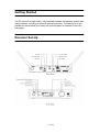
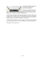
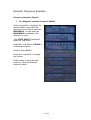
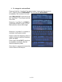
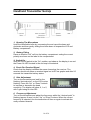
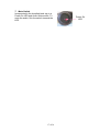
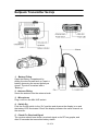
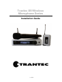
Trantec S5 Wireless
Microphone Series
Installation Guide
1 of 34
Contents
3.
Introduction, System Overview
4, 5.
Safety - Important Instructions
6 - 7.
Getting Started, Receiver Set-Up
8 - 11.
Receiver Frequency Selection
12 - 15.
Miscellaneous Settings
16, 17.
Handheld Transmitter Set-Up
18, 19.
Beltpack Transmitter Set-Up
20.
Operating Hints
21.
Troubleshooting Guide
22.
S5 System Accessories
23, 24.
S5 System Part Numbers
25, 26.
Rack Mount Kit
27.
Multi-Channel Configuration with ADU
28.
Antenna Head Amplifiers
29, 30.
Mini-XLR Wiring Connections
31, 32.
Technical Specifications
33.
Warranty
34.
CE Declaration of Conformity, WEEE Statement
2 of 34
Introduction
The Trantec S5 series represents our commitment to our customers by
providing high-quality, reliable Wireless audio links using our considerable
design expertise gained over many years as a leading edge manufacturer.
We would like to thank you for purchasing this product and would like you to
study this guide, especially the safety instructions before installing and using
this equipment.
S5 Series System Overview
The S5 series is a professional UHF wireless microphone system with
features including:
•
•
•
•
•
•
•
•
•
•
•
•
•
24 channel simultaneous operation (S5.3 12 channel)
10 preset banks including 1 custom user (S5.3 9 Banks)
True “dual receiver” diversity – to minimise drop-outs
Intuitive LCD and operating system on both receiver and transmitter
Infra-red programming for fast system set-up
Software transmitter function locks
Headphone monitoring as standard
XLR (switchable mic and line) and ¼ “jack AF outputs
AF processing menu (S5.5 only)
Over 1400 customer selectable channels
Fully integrated PC software monitoring facility via USB port
All metal construction of receiver and transmitters
Rack kit and front mounting antenna adaptors included (S5.5 only)
3 of 34
Safety
Our aim is to supply you with a product that provides you with countless
hours of trouble-free use. In order to achieve this goal we recommend the
following:
•
•
•
•
•
•
•
•
•
•
•
•
Keep the system away from direct sources of heat, e.g. Central heating
radiators, heaters and direct sunlight.
Do not expose the unit to an environment where it could be splashed
with liquids as this may result in fire or electric shocks.
Should the transmitters remain unused for an extended period of time
we recommend that the batteries are removed to avoid any potential
leakage.
Keep the system clean by using a slightly damp cloth. Never use
household cleaning agents or solvents.
Avoid using or storing the system in damp conditions.
Always use the AC power adaptor supplied with the receiver and
always disconnect from the AC outlet when not in use. Never remove
the external covers of the equipment, exposing the electronics, or
modify the unit in any way.
Do not handle the mains lead with wet hands
Never pull the cord of the AC adaptor, always grasp the main body of
the unit when connecting/disconnecting to an AC power outlet.
Route the AC power lead in such a way that it is not likely to be
stepped on or tripped over.
Do not use if the AC power lead becomes damaged. A damaged AC
lead may cause fire or give you an electric shock.
Never touch any part of the system during a thunderstorm as this may
result in severe electric shock.
Dispose of batteries responsibly. Do not break open or incinerate, and
do not place in household waste. Consult your local waste authority for
advice on disposal.
Should the covers be removed or there is any other breach of the above
instructions, the warranty becomes null and void, in addition to personal
risk from burns and/or electric shock.
If any of the following conditions occur when using the unit, switch off and
remove the AC adaptor from the AC outlet immediately and contact your
nearest dealer.
•
•
•
Smoke or unusual smell
Water or foreign metallic object inside unit
Physically damaged housings
4 of 34
5 of 34
Getting Started
The S5 series is a high quality, fully featured wireless microphone system with
many features, including an intuitive operating system. To enable you to get
started we recommend you initially set up the system as outlined in the next
few pages.
Receiver Set-Up
6 of 34
1. Attach the 2 supplied antennae to
the rear panel TNC antenna
connectors as shown left.
2. Connect the AC/DC adaptor into
the DC inlet as marked on the rear
panel, feeding the cable through the attached strain relief. Observe that the
front panel on-off switch surround is illuminated red.
3. Connect the rear panel audio output from either the ¼” jack or XLR to your
mixing console or amplifier. Note: the XLR balanced output can be switched
for either mic or line. The system can be also monitored from the headphone
socket, using the “Jog-Wheel” to adjust the volume level.
4. Switch the On/Off switch to the “On” position. The switch surround will now
be illuminated green and the receiver will default to its initial setting (BK1.01).
The system is now ready for use.
7 of 34
Receiver Frequency Selection
Frequency Selection Options
1. To change the selected channel in BANK1
Press and hold the “Jog-wheel” for
approximately 3 seconds if the
receiver is not in mute to enter the
MAIN MENU. You will enter the
MAIN MENU immediately if the
receiver is in mute.
With FREQ SELECT underlined
press the “Jog Wheel”.
Rotate the “Jog Wheel” till BANK is
underlined and press.
Press to select BANK1.
Rotate the “Jog-wheel” to change
the channel.
Finally, press to select the new
frequency. (See the attached
frequency table).
8 of 34
2. To change the selected Bank
Press and hold the “Jog-wheel” for approximately 3 seconds if the receiver is
not in `34as to enter the MAIN MENU. You will enter the MAIN MENU
immediately if the receiver is in mute.
With FREQ SELECT underlined press
the “Jog Wheel”. This will give you the
next menu.
Rotate the “Jog Wheel” until BANK is
underlined and press to give you the
Bank selection screen below right.
Rotate the “Jog Wheel” to underline a
new bank, then press to select.
Press to select the frequency shown or
rotate to change to another frequency
within this bank.
Press again with ACCEPT underlined
to accept the new bank. (See the
attached frequency table).
Go to step 4 to program the transmitter
via the receiver infra-red port.
9 of 34
3. To change the selected channel to a Custom single frequency
This option allows the customer to select 1 of over 1400 available channels.
Press and hold the “Jog-wheel” for approximately 3 seconds if the receiver is
not in mute to enter the MAIN MENU. You will enter the MAIN MENU
immediately if the receiver is in mute.
With FREQ SELECT underlined,
press the “Jog-wheel”. With SINGLE
underlined press the “Jog-wheel”.
With EDIT underlined press the “Jogwheel”. The first part of the frequency
will be flashing. Rotate the “JogWheel” to select this section of a new
frequency and press to accept. The
second part of the frequency will now
start flashing. Change the second part
of the new frequency as above. You
can then change each letter of the
user name in the same way. All ASCII characters are available for the user
name.
If you wish to exit this menu at any time, press and hold the “Jog-Wheel”.
Press the “Jog-Wheel” for 1 second to exit then rotate till ACCEPT is
underlined and press to select the new custom frequency and user name. Go
to the next step to program a transmitter via the receiver infra-red port.
Please note:
For S5.3 product the single user frequency will be added to the transmitter
with receiver Bank1. The S5.3 does not have USER bank.
In the case of the S5.5 it will be added to the Custom USER bank. You can
download USER banks via the Trantec software. Please refer to the software
manual on this CD for more information.
Units for the Japanese market do not have USER or SINGLE options in the
FREQUENCY SELECT menu.
10 of 34
4. Program a transmitter with Bank information via receiver Infra-red
port
Press and hold the “Jog-wheel” for approximately 3 seconds if the receiver is
not in mute to enter the MAIN MENU. You will enter the MAIN MENU
immediately if the receiver is in mute.
Rotate the “Jog Wheel” till TX SET is
underlined and press to enter TX
SETTINGS. With FREQUENCY
underlined, press the “Jog Wheel”.
Align the transmitter and receiver
infra-red windows with the
transmitter no more than 15 cm from
the receiver. With SEND underlined,
press the “Jog Wheel” and wait a few
seconds. All frequencies in the bank selected will be transferred to the
transmitter and its current frequency will be set to match the receiver’s current
frequency. The receiver will return to its main display.
For S5.5 - If the receiver is currently in a SINGLE or USER frequency, it will
transfer the USER bank.
For Japanese units - only fixed banks 1 to 6 are available.
For S5.3 - If the receiver is currently in a SINGLE frequency, it will transfer
Bank1.
11 of 34
Miscellaneous Settings
RX Settings
Mute/Squelch Settings
The S5 series uses sophisticated internal mute functions including Pilot Tone,
Noise and RSSI to prevent noise break through from external sources when
the transmitter is in the “OFF” position.
The RSSI (Received signal strength) portion is user adjustable via the RX
SETTINGS MENU. To Access this press the “Jog-Wheel” for 1 second and
enter the MAIN MENU, or for 3 seconds if not in mute.
Rotate till RX SET is underlined and
press. With MUTE underlined, press
the “Jog-Wheel”. Now rotate the “JogWheel” to adjust the mute setting
between 1 and 10, then press. A
marker shows the current mute setting
in relation to the RF A and B scales.
Please note: high mute settings will
decrease range and low mute settings
increase the interference potential. We
recommend a setting of 4 to 6. The
mute level changes in real time as the
setting is varied.
Audio Processing (S5.5 only)
Press the “Jog-Wheel” to enter the
MAIN MENU. Rotate till RX SET is
underlined then press. On the RX
SETTINGS menu, rotate till AUDIO is
underlined and press. Options
available here are PHASE REV,
LoCUT, and HiBOOST. The default
factory setting for all these options is
OFF. Navigate to each option by rotating the “Jog-Wheel” and press to check
the box for each option when it is underlined.
PHASE REV – reverses the audio output phase.
LoCUT – reduces the low frequency response.
HiBOOST – increases the high frequency response.
12 of 34
All three of the above functions
change in real time as the option is
selected. Rotate the “Jog-Wheel” to
underline EXIT after making your
selections, and press to return to the main screen.
Headphone Volume
Rotate the “Jog-Wheel” while the
main screen is showing to go to the
headphone volume adjustment. A bar
graph of the volume is shown and can
be altered by again turning the “Jog-Wheel”. Push to exit and return to the
main screen. The unit will return to the main screen automatically if there is no
user intervention for approximately 2 seconds. Any change you have made
will be saved.
Scanning
The scanning feature can determine which frequencies are currently being
used in the vicinity of your receiver.
From the main screen press the “JogWheel” to go to MAIN MENU, rotate
till FREQ SEL, is underlined and
push. Then rotate till SCAN is
underlined and push. The scanning
process takes about 10 seconds and
you will then be shown the Bank
selection screen. If interference is
found on a frequency during the scan,
the bank containing that frequency is
made unavailable on the receiver.
You can then select any bank from
those available, and any frequencies from within those banks.
13 of 34
Pilot Tone
The S5 series has the ability to
disable the pilot tone as a means of
either identifying outside interference
or allowing compatibility with non-pilot
tone devices. The default factory
setting is ON.
To disable Pilot Tone press the “JogWheel” to go to MAIN MENU. Rotate
till RX SET is underlined and push to
go to the RX SETTINGS menu.
Rotate the “Jog-Wheel” to underline
PILOT and press to uncheck the box.
Rotate the “Jog-Wheel” to exit this
screen, and press to return to the
main screen.
Phantom Power
DC added to the antenna inputs for
powering head amplifiers. The default
factory setting is OFF. Push the “JogWheel” to show the MAIN MENU.
Rotate the “Jog-Wheel” to underline
RX SETTINGS, and push to show the
next menu. Rotate to underline
PHANTOM, and push. Press to check
the PHANTOM PWR box. Rotate and
then press to choose EXIT and return
to the main screen.
LCD Contrast
Push the “Jog-Wheel” to bring up the
MAIN MENU. Rotate the “Jog-Wheel”
to underline RX SETTINGS. Rotate to
underline LCD and push, then rotate
the “Jog-Wheel” to alter the LCD
CONTRAST. Push to exit and return to the main screen. The unit will return to
the main screen automatically if there is no user intervention for approximately
2 seconds. Any change you have made will be saved.
14 of 34
TX Settings
Lock TX Switch
To prevent unauthorised or accidental changes of frequency or gain on a
transmitter, or accidentally turning a transmitter off during a performance you
can lock these features from the receiver.
Press the “Jog-Wheel” to show the
MAIN MENU. Rotate the “Jog-Wheel”
to underline TX SET and push to select
this option. Rotate the “Jog-Wheel” till
LOCK is underlined and push to select
this. Push the “Jog-Wheel” to check the
box for POWER if required, or rotate to
go to FREQ/GAIN and push to check
this box if required.
Rotate till EXIT is underlined and push.
You will then have the option to SEND
the TX Locks you have selected, to a
transmitter or CANCEL. If you are
sending Locks to a transmitter you
should hold it within 15cm of the
receiver and with the infra-red windows
of each aligned.
15 of 34
Handheld Transmitter Set-Up
1. Opening The Microphone
Undo the handheld sleeve by unscrewing the end cap at the base anticlockwise and then gently sliding the sleeve down to expose the LCD and
Battery compartment.
2. Battery Fitting
Place an Alkaline “AA” cell into the battery compartment noting the correct
polarity as shown on the label in the compartment.
3. Switch On
Slide the On/Off switch to the “On” position and observe the display is on and
the Power On LED located in the end cap is illuminated.
4. Check For Received Signal
Check that the display indicates the same channel as the receiver. The
receiver should now show a received signal on its RF bar graphs and after 20
seconds the transmitter battery status.
5. Gain Adjustment
Turn on the transmitter and wait for the
flashing “decimal point” on the LCD to stop
flashing. Press the “Up” or “Down” buttons
to increase or decrease the head
sensitivity. The display will show 0, 1 or 2,
with 0 gain being for max SPL.
6. Frequency Adjustment
Turn on the transmitter and adjust the frequency whilst the “decimal point” is
flashing (approx 6 secs) via the “Up” or “Down” buttons. When the correct
frequency is selected, turn the transmitter off then on again to activate the
newly selected channel.
16 of 34
7. Mute Switch
Incorporated in the handheld end cap is a
Power On LED and Audio Mute switch. To
mute the audio, flick the switch towards the
LED.
17 of 34
Power On
LED
Beltpack Transmitter Set-Up
1. Battery Fitting
Open the battery compartment by
sliding the door forward and up. Insert a
battery observing the correct polarity as
shown. The door is marked with a
“Battery +”.
2. Antenna Fitting
Screw the antenna into the antenna bush
3. Microphone
Plug a mic into the Mini-XLR socket.
4. Switch On
Flick the On/Off switch to the “On” position and observe the display is on and
the battery LED illuminated. Check the display indicates the same channel as
the receiver.
5. Check For Received Signal
The receiver should now show a received signal on its RF bar graphs, and
after 20 seconds the transmitter battery status.
18 of 34
6. Beltpack AF Gain Adjusment
Turn the transmitter on and wait for the flashing “decimal point” on the LCD to
stop flashing. Press the “Up” or “Down” buttons firmly to increase or decrease
the AF gain. There are 10 steps with “0” being minimum.
7. Frequency Adjustment
Turn the transmitter on and adjust the frequency while the “decimal point” is
flashing (approx 6 secs) via the “Up” or “Down” buttons. When the correct
frequency is selected, turn the transmitter off then on again to activate the
newly selected channel.
19 of 34
Operating Hints
To maximise operating performance Trantec recommends the following:
•
Ensure good line of sight between the receiver antennae and
transmitter, and avoid obstructions, e.g. concrete walls and metal
structures.
•
Always ensure the receiver antennae are at least 3 M (10 ft) away from
the transmitters at all times.
•
Always ensure the transmitters are separated by at least 50 cm.
•
Never position the transmitter antenna directly against the body or the
hand. This will reduce the operating range.
•
Ensure the correct setting of the Mute for effective control of
interference whilst the transmitter is turned off. The default is normally
4-6 but may need to be increased with multi-channel set-ups.
•
Do not mix separate Banks in multi-channel set-ups.
•
Use the SCAN function to check for external interference.
•
Set the transmitter AF gain so the receiver VU indicates 0 db with
occasional peaks to +6 dB.
•
Keep the microphone/instrument lead away from the antenna on the
beltpack.
•
Do not mix with other brands of Wireless Microphone as Trantec
cannot guarantee multi-channel compatibility.
20 of 34
Troubleshooting Guide
• No operation of Transmitter
Replace the current battery with a fresh one of the correct Alkaline “AA”
type.
• No RF signal on receiver
Check the transmitter and receiver are “Tuned” to the same channel.
• Poor range
Check the mute level setting. For normal range we recommend a mute
setting of 4-6.
• AF Signal distorted
Check the receiver XLR mic-line switch for a correct match to your
Mixer/Amplifier. Reduce the gain of the transmitter if the VU meter shows
over 6dB.
• AF Signal low level with high background noise
Adjust the transmitter gain so the VU bar graph shows 0dB with 6dB
peaks.
• External Head amplifiers not operating
Check for shorts in the leads and ensure the receiver PHANTOM PWR is
switched on via the RX SETTINGS menu.
• Receiver LCD contrast poor
Enter the receiver RX SETTINGS menu, select LCD and press then rotate
the “Jog-Wheel” to adjust the contrast. The receiver will automatically exit
after a few seconds.
21 of 34
S5 System Accessories
S5RACK
S/PSU-U
S/ADU-D3-U
ACC/S4.16RK
LD/SMC-TNC
LD/TNC-TNC5M
LD/TNC-TNC10M
LD/N-TNC5M
LD/N-TNC10M
19" Rack mount kit for S5 Receivers (complete with Antenna Mount)
5-way power supply for 4 x S5.3 / S5.5 Receivers & 1 x S/ADU (UK
version)
Antenna Distribution for 4 x S5.3 / S5.5 Receivers (D3 band UK)
19" Rack mount kit for 2 x S/ADU-D3-U
Cable, Receiver > ADU, 37cm
Cable: 5M, RG58 TNC - TNC
Cable: 10M, RG58 TNC - TNC
Cable: 5M, RG213 N type - TNC
Cable: 10M, RG213 N type - TNC
ANT/UHF-GP
ANT/6000RD
ANT/BOOST2
ANT/BRK
ACC/HL-06A3
ACC/5BPCLIP
Ground plane antenna (bands available: A1/B1, C1/D3)
UHF wideband remote dipole antenna (bands available: A1/B1, C1/D3)
Antenna amplifier for S/ADU (bands available: A1, B1, C1, D3)
Stand adaptor/mounting bracket for antenna amplifier (ANT/BOOST)
Microphone clip for wireless handheld transmitter
Spare beltpack clip assembly
ACC/6K-POUCH
Grey microphone pouch for S5 HDX/HCX
ACC/5KLTX-POUCH Leather pouch for S5 LTX
ANT/UHF-RA-5
ANT/5.5LTX
Spare antenna for S5.3 / S5.5 Receiver (bands A1/B1 & C1/D3)
Spare antenna for S5.3 / S5.5 LTX (bands A1/B1 & C1/D3)
PS/S115UK
PS/S115EU
PS/S115AU
PS/S115US
Power supply 220Vac > 13Vdc (UK 3 pin)
Power supply 220Vac> 13Vdc (European 2 pin)
Power supply 220Vac > 13Vdc (Australian 2 pin)
Power supply 110Vac > 13Vdc (American 2 pin)
MIC/X2
ACC/LP2-TC
MIC/X259
MIC/X55
MIC/X212
Lavalier Microphone
Spare tie clip for MIC/X2 Lavalier Microphone
Lavalier Microphone
Lavalier Microphone
Lavalier Hi-Q microphone in Black or Pink with or without 12dB pad
MIC/X10
MIC/X66
MIC/X22-B
Headworn Omni-Directional Microphone
Aerobic Headworn Microphone - in Black, Blue or Yellow
Headworn Hi-Q Microphone – Black & Pink, with or without 12dB pad
MIC/DA09
DA-CAPPO Single Ear Microphone
ACC/MXLR-JAC
Guitar Lead (1/4” Jack – 4 Pin Mini-XLR Plug)
PLG/MXLR
4 Pin Mini-XLR Plug
22 of 34
S5 System Part Numbers
S5.3 Product Codes & Description
Model No
Description
Pwr Supply
Frequency
S5.3-HD-D2U
S5.3-HC-D2U
S5.3-L-D2U
S5.3-LH-D2U
S5.3-RX-D2U
S5.3-HDX-D2W
S5.3-HCX-D2W
S5.3-LTX-D2W
UHF Handheld System c/w Cardioid Dynamic Capsule
UHF Handheld System c/w Condenser Capsule
UHF Lapel System c/w Lavalier Microphone
UHF Aerobic System c/w Aerobic Headmic
UHF Receiver
UHF Handheld Transmitter (Dynamic Cardioid Capsule)
UHF Handheld Transmitter (Condenser Capsule)
UHF Beltpack Transmitter (c/w Lavalier Microphone)
UK
UK
UK
UK
UK
n/a
n/a
n/a
854-865MHz
854-865MHz
854-865MHz
854-865MHz
854-865MHz
854-865MHz
854-865MHz
854-865MHz
S5.3-HD-D2E
S5.3-HC-D2E
S5.3-L-D2E
S5.3-LH-D2E
S5.3-RX-D2E
UHF Handheld System c/w Cardioid Dynamic Capsule
UHF Handheld System c/w Condenser Capsule
UHF Lapel System c/w Lavalier Microphone
UHF Aerobic System c/w Aerobic Headmic
UHF Receiver
EU
EU
EU
EU
EU
854-865MHz
854-865MHz
854-865MHz
854-865MHz
854-865MHz
S5.5 Product Codes & Description
Model No
Description
Pwr Supply
Frequency
S5.5-HD-D3U
S5.5-HC-D3U
S5.5-L-D3U
S5.5-LH-D3U
S5.5-RX-D3U
S5.5-HDX-D3W
S5.5-HCX-D3W
S5.5-LTX-D3W
UHF Handheld System c/w Cardioid Dynamic Capsule
UHF Handheld System c/w Condenser Capsule
UHF Lapel System c/w Lavalier Microphone
UHF Aerobic System c/w Aerobic Headmic
UHF Receiver
UHF Handheld Transmitter (Dynamic Cardioid Capsule)
UHF Handheld Transmitter (Condenser Capsule)
UHF Beltpack Transmitter (c/w Lavalier Microphone)
UK
UK
UK
UK
UK
n/a
n/a
n/a
830-865MHz
830-865MHz
830-865MHz
830-865MHz
830-865MHz
830-865MHz
830-865MHz
830-865MHz
S5.5-HD-D3E
S5.5-HC-D3E
S5.5-L-D3E
S5.5-LH-D3E
S5.5-RX-D3E
UHF Handheld System c/w Cardioid Dynamic Capsule
UHF Handheld System c/w Condenser Capsule
UHF Lapel System c/w Lavalier Microphone
UHF Aerobic System c/w Aerobic Headmic
UHF Receiver
EU
EU
EU
EU
EU
830-865MHz
830-865MHz
830-865MHz
830-865MHz
830-865MHz
S5.5-HD-C1U
S5.5-HC-C1U
S5.5-L-C1U
S5.5-LH-C1U
S5.5-RX-C1U
S5.5-HDX-C1W
S5.5-HCX-C1W
S5.5-LTX-C1W
UHF Handheld System c/w Cardioid Dynamic Capsule
UHF Handheld System c/w Condenser Capsule
UHF Lapel System c/w Lavalier Microphone
UHF Aerobic System c/w Aerobic Headmic
UHF Receiver
UHF Handheld Transmitter (Dynamic Cardioid Capsule)
UHF Handheld Transmitter (Condenser Capsule)
UHF Beltpack Transmitter (c/w Lavalier Microphone)
UK
UK
UK
UK
UK
n/a
n/a
n/a
794-830MHz
794-830MHz
794-830MHz
794-830MHz
794-830MHz
794-830MHz
794-830MHz
794-830MHz
Cont…
23 of 34
S5.5 Product Codes & Description, cont.
Model No
Description
Pwr Supply
S5.5-HD-C1E
S5.5-HC-C1E
S5.5-L-C1E
S5.5-LH-C1E
S5.5-RX-C1E
UHF Handheld System c/w Cardioid Dynamic Capsule
UHF Handheld System c/w Condenser Capsule
UHF Lapel System c/w Lavalier Microphone
UHF Aerobic System c/w Aerobic Headmic
UHF Receiver
EU
EU
EU
EU
EU
794-830MHz
794-830MHz
794-830MHz
794-830MHz
794-830MHz
S5.5-HD-C1A
S5.5-HC-C1A
S5.5-L-C1A
S5.5-LH-C1A
S5.5-RX-C1A
UHF Handheld System c/w Cardioid Dynamic Capsule
UHF Handheld System c/w Condenser Capsule
UHF Lapel System c/w Lavalier Microphone
UHF Aerobic System c/w Aerobic Headmic
UHF Receiver
AU
AU
AU
AU
AU
794-830MHz
794-830MHz
794-830MHz
794-830MHz
794-830MHz
S5.5-HD-B1A
S5.5-HC-B1A
S5.5-L-B1A
S5.5-LH-B1A
S5.5-RX-B1A
S5.5-HDX-B1W
S5.5-HCX-B1W
S5.5-LTX-B1W
UHF Handheld System c/w Cardioid Dynamic Capsule
UHF Handheld System c/w Condenser Capsule
UHF Lapel System c/w Lavalier Microphone
UHF Aerobic System c/w Aerobic Headmic
UHF Receiver
UHF Handheld Transmitter (Dynamic Cardioid Capsule)
UHF Handheld Transmitter (Condenser Capsule)
UHF Beltpack Transmitter (c/w Lavalier Microphone)
AU
AU
AU
AU
AU
n/a
n/a
n/a
722-752MHz
722-752MHz
722-752MHz
722-752MHz
722-752MHz
722-752MHz
722-752MHz
722-752MHz
S5.5-HD-B1S
S5.5-HC-B1S
S5.5-L-B1S
S5.5-LH-B1S
S5.5-RX-B1S
UHF Handheld System c/w Cardioid Dynamic Capsule
UHF Handheld System c/w Condenser Capsule
UHF Lapel System c/w Lavalier Microphone
UHF Aerobic System c/w Aerobic Headmic
UHF Receiver
US
US
US
US
US
722-752MHz
722-752MHz
722-752MHz
722-752MHz
722-752MHz
S5.5-HD-A1S
S5.5-HC-A1S
S5.5-L-A1S
S5.5-LH-A1S
S5.5-RX-A1S
S5.5-HDX-A1W
S5.5-HCX-A1W
S5.5-LTX-A1W
UHF Handheld System c/w Cardioid Dynamic Capsule
UHF Handheld System c/w Condenser Capsule
UHF Lapel System c/w Lavalier Microphone
UHF Aerobic System c/w Aerobic Headmic
UHF Receiver
UHF Handheld Transmitter (Dynamic Cardioid Capsule)
UHF Handheld Transmitter (Condenser Capsule)
UHF Beltpack Transmitter (c/w Lavalier Microphone)
US
US
US
US
US
n/a
n/a
n/a
692-722MHz
692-722MHz
692-722MHz
692-722MHz
692-722MHz
692-722MHz
692-722MHz
692-722MHz
24 of 34
Frequency
S5 Series Rack Mount Kit
19” Rack Mounting for 2 x S5 Series Receivers
The rack mounting kit is supplied as standard with S5.5 systems, or is
available as an accessory for S5.3 systems.
1. Unscrew the front 3 lid retaining screws from opposite
sides of each receiver case and fit the angled rack
brackets, using the supplied screws. There are 3 of these
supplied with each receiver.
2. Remove the 2 plastic plugs from the top of the receiver
lid and fit a metal joining strip (2 supplied per receiver) in the slots at the side
of each lid of the 2 receivers. Carefully fit the M3x6 screws (1 supplied with
each receiver, coloured black).
3. Fit 2 joining strips across the bottom of the receiver chassis
using 4 M3x6 CSK screws (2 supplied per receiver).
25 of 34
19” Rack 1 x S5 Series Receiver with Front Mount Antennae
The rack mounting kit is supplied as standard with S5.5 systems, or is
available as an accessory for S5.3 systems.
1. Unscrew 3 x lid retaining screws (M3x6) from the front left side of the
chassis (viewed from the front) and fit the small angled rack bracket, using
the supplied screws. There are 3 of these supplied with each receiver.
2. Unscrew 3 x lid retaining
screws (M3x6) from the front
right side of the chassis and fit
the supplied long angled
bracket using the screws
supplied.
3. Fit the 2 supplied antenna
extension cables into the front panel long bracket and tighten their TNC
nuts. Screw the TNC plugs of each into the antenna sockets on the rear of
the receiver. Should front mount antennae not be required, fit the 2 plastic
blanking plugs supplied into the spare holes.
26 of 34
Multi-Channel Configuration with ADU
The S5 series is designed for simultaneous use of several systems. Ensure
each system is assigned a different operating channel. Use only channels
from one bank to ensure multi-channel compatibility. Try to ensure that each
transmitter is separated by 0.5 M (1.5 ft) during operation.
It is recommended that for systems with 4 or more channels the Trantec
Antenna Distribution Unit (ADU) is used. This allows the use of only one set of
antennae to feed several receivers. Each ADU is capable of driving 4 units
simultaneously with separate outputs for additional ADU units.
The diagram below shows a typical 12 channel installation. Each ADU comes
complete with all necessary connecting leads for 4 channels. A 19” rack tray is
available as an accessory for mounting one or two ADU units. Trantec
recommends that a maximum of 12 channels is wired as illustrated below. For
larger installations please consult www.trantec.co.uk
To channels 9 - 12
ANT B
ANT A
ADU1
ADU2
27 of 34
Antenna Head Amplifiers
Trantec head amplifiers are designed to reduce the effect of long RF antenna
cable runs between the receivers or ADUs and remote antennae. The S/ADU
and S5 Series Receiver can supply power to the head amplifier.
Please note: head amplifiers can introduce some unwanted effects, such as
RF blocking and increased intermodulation, especially in multi-channel
applications. To minimise such effects Trantec offers the following guidelines:
1. For cable runs of greater than 10 M and less than 20 M, when using RG58
cable, insert a head amplifier (attenuation @ 830 MHz is approx 5 dB per
10 M).
2. For cable runs of greater than 20 M and less than 40 M, when using
RG213 cable, insert a head amplifier (attenuation @ 830 MHz is approx
2.5 dB per 10 M). 40 M is the recommended maximum length of cable run.
3. Ensure that transmitters are always at least 3 M from the remote receiver
antennae at any time.
4. Always test the installation without the use of head amplifiers first. Only
insert these if the range is found to be inadequate and below normal
operating range.
5. Always ensure that the overall system RF gain does not exceed 6 dB.
6. Always insert head amplifiers at the remote antenna end of the installation.
7. The antenna head amplifier is NOT designed for outdoor installation and
should not be operated in damp conditions.
28 of 34
Mini-XLR Wiring Connections
Beltpack Audio Mini-XLR Connections
1.
2.
3.
4.
Ground
Bias 5 V
AF Hi-Z
AF Load Resistor
Solder connections for Mini-XLR flying socket
4
3
1
2
29 of 34
Wiring for Mini-XLR Flying Socket
2 Wire Mic
Pin 1: Ground
Pin 2: 5 V
Pin 3: AF
Pin 4: Internal AF load resistor
Link pins 3 and 4 and add a 10 K bias
resistor as illustrated
3 Wire Mic
Pin 1: Ground
Pin 2: 5 V
Pin 3: AF
Pin 4: Internal AF load resistor
Link pins 3 and 4 as illustrated
Hi Impedance Guitar/Instrument
Pin 1: Ground
Pin 2: 5 V - Not connected
Pin 3: AF Hi Z
Pin 4: Not connected
Connect screened cable to pin 1
ground and pin 3 AF Hi-Z
Lo Impedance Microphone (No Phantom)
Pin 1: Ground
Pin 2: 5 V - Not connected
Pin 3: AF Hi-Z
Pin 4: Internal AF load resistor
Link pins 3 and 4 and connect screened cable to
pin 1 ground and pins 3 and 4 as illustrated
30 of 34
Technical Specifications
Overall System
Frequency Bands available:
D1 863-865 MHz, D2 854-865 MHz (S5.3 only)
D3 830-865 MHz, C1 794-830 MHz
B1 722-752 MHz, A1 692-722 MHz
RF Switching BW: 36 MHz typ.
RF grid spacing: 25 kHz
RF Bandwidth: < 200 kHz
AF Frequency response: 60 Hz – 20 kHz
AF Distortion: < 0.8% at nom deviation 22 kHz
AF Dynamic range: >110 dBA
AF Noise reduction: Trantec proprietary
Temperature range: -10 °C to +55°C
Receiver Specification
Type: Dual Diversity featuring PLL Dual Double conversion receivers
IF Freq: 1st IF 55.875 MHz; 2nd IF 10.7 MHz
Sensitivity: < 1 uV/12 dB SINAD
Ist Image: >70 dB
RSSI range: 10 steps 30 dB range
Antenna Inputs: TNC 50 Ohms
AF switches: Low Cut – High Boost – Phase Reversal (S5.5 only)
AF Output level: XLR Line +15 dBm max; XLR Mic -25 dBm max; Unbalanced ¼”
jack socket +9 dBm max
Antenna Phantom: 9 V @ 60 mA short-circuit protected on each RF port
Bank Specification: 10 banks x 24 channels (S5.5) (6 banks Japanese version); 9
banks x 12 channels S5.3
Infra-Red Link: Range 15 cm max
Computer Interface: Computer monitoring via rear panel USB interface
Power Consumption: 300 mA @ 12 Vdc nominal
Transmitter Specification
Power Supply: Single Alkaline “AA” cell 1.5 V nom.
Power consumption: typically 120 mA
Operating time: typically 8 - 10 hrs min.
Controls: On-Off, AF Gain Adjust, Frequency adjust, AF Mute (Handheld)
Gain Range: Beltpack +2 dBm to -20 dBm in 10 steps. Handheld 3 steps 6 dB
Handheld dimensions: 32 mm x 250 mm; Weight 350 g; Grille diameter 51 mm
Beltpack dimensions: 55 mm x 80 mm x 20 mm; Weight 110 g
Due to our continual policy of research and development we reserve the right to alter
specifications without prior notice.
31 of 34
Handheld Capsule Specification
Type: Audio-Technica MU-36B
Polar Pattern: Hyper Cardioid
Sensitivity: -51 dB ± 3 dB
Element: Moving Coil (dynamic)
Frequency Response: 100 – 10000 Hz
Impedance: 600 Ohms ± 30% at 1 kHz
Lavalier Microphone Specification
Directional Characteristics: Omni-Directional
Element: Back Electret-Condenser
Impedance: 4 kOhms ± 30% at 1kHz
Cable: 1.3 M x 2.2 mm
Weight: 20.5 g (excl accessories)
Frequency: 50 Hz – 18 kHz
Sensitivity: -54 dB ± 3 dB
Dimensions: 10.5 x 24.7 mm
Connector: 4 Pin Mini-XLR
Due to our continual policy of research and development we reserve the right to alter
specifications without prior notice.
32 of 34
Warranty
All Trantec products are guaranteed for a period of 12 months from the date of
purchase against defects in materials and workmanship. In the event of a
claim under guarantee the product should be returned in its original packing to
an Authorised Service Centre or BBM Electronics, together with proof of
purchase, i.e. sales purchase receipt from an authorised dealer.
BBM will repair or replace the device at its discretion. BBM offers no warranty
whatsoever under the following circumstances: mechanical damage, incorrect
operation, incorrect voltage, wear and tear, and defects that were known at
the time of purchase. In addition, the warranty will be null and void in the
event of unauthorised repair or modification, including removal of any of its
covers.
E&OE. Due to our continual policy of research and development we reserve
the right to alter specifications without prior notice.
Trantec Systems
BBM Electronics Group Ltd
Kestrel House
Garth Road
Morden
Surrey
SM4 4LP
UK
Tel: +44 (0) 20 8330 3111
Fax: +44 (0) 20 8330 3222
E-Mail: enquiries@trantec.co.uk
Web: http://www.trantec.co.uk
33 of 34
CE Declaration of Conformity
This equipment is in compliance with the essential requirements and other relevant
provisions of Directives 1999/5/EC, 89/336/EC or 73/23/EC.
More information is available from www.trantec.co.uk
IMPORTANT NOTICE. Before using this wireless microphone system, please
observe the requirements of each country with respect to frequency allocations and
individual licensing requirements.
WEEE Statement
This symbol indicates that this piece of electrical/electronic equipment
must be disposed of separately from normal waste at the end of its
operational life. Please dispose of this product by taking it to your
local recycling or collection point.
BBM Electronics Group Ltd
www.trantec.co.uk
34 of 34
A subsidiary of TOA Corporation