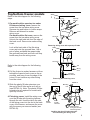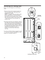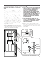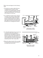
1
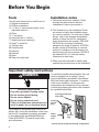
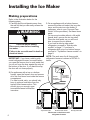
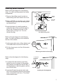
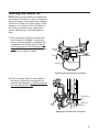
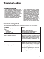
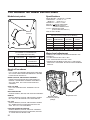
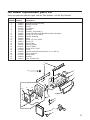
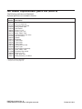
Home
Appliances
Installation
G
U
I
D
E
Table of Contents
(complete) ................... 2
Requesting Assistance
or Service ....................... 2
Important Information ... 3
Before You Begin .......... 4
Installing the
Ice Maker ........................ 6
Installing the
Water Line .................... 16
Final Installation .......... 22
Starting the
Ice Maker ...................... 24
Troubleshooting .......... 25
MODULAR ICE MAKER KIT
PART NO. 2181913 Rev. A
www.whirlpool.com
Table of
Contents
Page
Requesting Assistance or Service ........... 2
Important Information .............................. 3
Before You Begin ....................................... 4
Tools ........................................................ 4
Installation notes ...................................... 4
Important safety instructions .................... 4
Components ............................................ 5
Installing the Ice Maker .............................. 6
Making preparations ................................ 6
Side-by-side models ................................ 7
Top/bottom freezer models ...................... 9
Installing the tubing clips ....................... 10
Preparing the water valve tubing
(for bottom freezers only)....................... 11
Mounting the water valve ....................... 12
Connecting the water valve tubing......... 13
Mounting the ice maker ......................... 14
Requesting
Assistance or
Service
If you need assistance, contact your dealer,
or call the Whirlpool Consumer Assistance
Center toll-free, 1-800-253-1301, 24 hours a
day.
2
Page
Routing the copper tubing ..................... 17
Installing the shut-off valve .................... 18
Connecting the copper tubing
to the shut-off valve ............................... 19
Connecting the copper tubing
to the water valve................................... 20
Turning the water on .............................. 21
Final Installation ....................................... 22
Installing the access cover and
forming the copper tubing ...................... 22
Connecting the power/
leveling the unit ...................................... 23
Starting the Ice Maker .............................. 24
Troubleshooting ....................................... 25
Operational notes .................................. 25
Troubleshooting chart ............................ 25
The modular ice maker service sheet .... 26
Ice maker replacement parts list ............ 27
Important Information
The following information is used throughout this Installation Guide. Read it carefully so you
are familiar with it.
Your safety and the safety of others are very important.
We have provided many important safety messages in this manual and on your
appliance. Always read and obey all safety messages.
This is the safety alert symbol.
This symbol alerts you to potential hazards that can kill or hurt you
and others.
All safety messages will follow the safety alert symbol and either the
word “DANGER” or “WARNING.” These words mean:
DANGER
You can be killed or seriously injured if
you don’t immediately follow
instructions.
WARNING
You can be killed or seriously injured if
you don’t follow instructions.
All safety messages will tell you what the potential hazard is, tell you how to
reduce the chance of injury, and tell you what can happen if the instructions are
not followed.
• This Installation Guide gives you complete
instructions on how to install the Ice Maker
Kit in your refrigerator-freezer and connect
a water line to it. Please read the guide
carefully and follow the instructions exactly
as described. Also, make sure that you
observe all of the “safety” instructions.
• This kit is designed so that almost anyone
can install it; however, a certain amount of
mechanical ability is required.
• Before you start to install your Ice Maker
Kit, you will have to purchase a copper
tubing kit that contains a “Regular Valve
and Clamp Assembly” (for refrigerators with
an automatic ice maker, or self-filling trays).
The kit contains all of the hardware
necessary to connect your ice maker to the
water supply. You can purchase one at
most hardware or plumbing supply stores.
• DO NOT USE PIERCING-TYPE, OR 3⁄16"
SHUT-OFF VALVES. They reduce the flow
of water to the ice maker, and are easily
clogged.
• DO NOT USE POLYETHYLENE TUBING
to connect the ice maker to the water line.
Use only 1⁄4" (O.D.) copper tubing.
CUSTOMER INSTALLATION IS NOT
WARRANTED BY THE REFRIGERATOR
OR ICE MAKER MANUFACTURER.
3
Before You Begin
Tools
Installation notes
You will need these tools to install your kit.
1. Regular screwdriver
2. Phillips screwdriver
3. 7⁄16" and 1⁄2" open-end wrenches (or an
adjustable wrench)
4. Pliers
5. 1⁄4" nut driver
6. Hand drill with 1⁄4" drill bit
7. Small hand level (optional)
8. Small 3⁄4-round file
9. Tubing cutter
10.Center punch
11.Hammer
12.Scissors
13.Ruler
14.Step stool (optional)
1. Follow the instructions carefully. Read
through the entire step so that you
understand it before you perform it.
2. The illustrations in this Installation Guide
are meant to clarify the installation steps
you need to perform. For each set of steps
shown, refer to the diagram immediately
beside or below the text for clarification.
Some illustrations also contain “DETAILS.”
DETAILS are contained in bubbles
alongside the larger illustration. A DETAIL
shows a close-up illustration of a certain
portion of a diagram or an illustration of a
specific step you are to perform. DETAILS
are labeled A, B, or C and are clearly
referenced in each step.
3. When you are instructed to install a part,
position the part as shown in the illustration.
Important safety instructions
WARNING
Electrical Shock Hazard
Plug into a grounded 3 prong outlet.
Do not remove ground prong.
Do not use an adapter.
Do not use an extension cord.
Failure to follow these instructions can
result in death, fire, or electrical shock.
If you intend to use power tools, such as an
electric drill, during the installation, make sure
that the AC receptacle is properly grounded
in accordance with the National Electrical
Code (ANSI/NFPA 70) and all local codes
and ordinances.
To minimize possible shock hazard, the cord
must be plugged into a mating 3-prong
ground-type outlet, grounded in accordance
with local codes and ordinances. If a mating
outlet is not available, it is the personal
responsibility and obligation of the customer
to have the properly grounded outlet installed
by a qualified electrician.
3-prong ground-type
wall outlet
3-prong
ground
plug
Power
supply
cord
Ground
plug
Correct power receptacle and plug configuration
4
BEFORE YOU BEGIN
Components
Remove the contents from the shipping carton
and set them on a table where they can be
easily identified and located. Check all of the
components in the kit against the following list
to help you become familiar with them. When
you identify a component, place a check
mark ( 3) after it. The KEY numbers
correspond to the “Component Illustrations.”
IMPORTANT: When you remove the water
valve and flexible tubing from the styrofoam
packing insert, do not remove the tubing from
the valve. It has been factory-installed and
leak-tested. Do not disturb the compression
nut that connects the tubing to the valve, or
the valve may leak after you connect it to the
water supply.
Do not discard any of the packing material
until you account for all of the components. If
you need to order a replacement part for the
Ice Maker, a replacement parts list is provided
on page 27.
COMPONENT ILLUSTRATIONS
KEY QTY. DESCRIPTION
1
2
3
4
5
6
7
8
9
10
11
12
13
14
1
1
1
1
1
1
1
2
2
1
1
4
2
2
Ice maker
Ice bucket
Water valve w/tubing
Fill tube
Gasket
Short extension tube
Long extension tube*
Ice maker clips*
Tubing clips
Metal water tube insert
Water valve tubing clamp
1⁄2" hex-head sheet-metal screws
1⁄2" hex-head machine screws
3⁄4" hex-head sheet-metal screws
* For installation in Side-By-Side Models only.
➀
➁
➃
➄
➂
➆
➉
11
➇
➈
14
➅
12
13
5
Installing the Ice Maker
Making preparations
Refer to the illustration below for the
following steps.
1. Carefully pull the refrigerator away from
the wall so that you can easily access the
rear panel.
WARNING
Electrical Shock Hazard
Disconnect power before installing
ice maker.
Failure to do so could result in death or
electrical shock.
IMPORTANT: If you have a side-by-side
model refrigerator-freezer, be careful when
you open the freezer door to work inside that
you do not force the door against the stop at
the bottom of the door. If you bend the stop,
the door will not close properly.
3. On an appliance with a bottom freezer,
remove the slide-out basket, the ice cube
trays, and the wire ice cube holder (if
necessary, refer to your “Use and Care
Guide” for the procedure). Set these items
aside.
On top-mount models without a full-width
freezer shelf, remove the ice tray shelf.
Place the shelf aside, as you will use it
later to support the ice bucket.
If you have a side-by-side model
refrigerator, proceed to “Side-by-side
models” on page 7. If you have a
refrigerator with a top or a bottom freezer,
proceed to “Top/bottom freezer models” on
page 9.
NOTE: The work area for all three model
refrigerator-freezers is shown in DETAIL A
below.
Detail
2. On appliances with a top or a bottom
freezer, open the freezer door and remove
all of the food items from inside the freezer
compartment.
For side-by-side units, you should only
have to remove food items from the
top half of the freezer section. This
should give you enough room
to access the areas to install the
ice maker.
Rear wall
left side
of freezer
compartment
Rear wall
Power
cord
plug and
receptacle
Power
cord
plug and
receptacle
Top freezer model
6
You will be
working in
these areas
Rear wall
Power
cord
plug and
receptacle
Bottom freezer model
Work areas on the three model
refrigerator-freezers
Side-by-side model
INSTALLING THE ICE MAKER
Side-by-side models
Refer to the side diagram for the following
steps. You will be working inside the freezer
compartment.
1. Remove the phillips screw from the ice
maker wiring cover and remove the cover.
Insert pin
into hole
Hole
Pin
Hole cover
Slot
Wiring
harness
2. Refer to DETAIL A, and with a pair of pliers,
break away the tabs from the wiring cover
and discard them.
Tab
DETAIL A
3. Insert the blade of a small screwdriver
under the edge of the round hole plug for
the fill tube, (located at the back of the
freezer liner), and pry it out. You can
discard the plug.
Phillips
screw
Insert tab
into slot
Wiring
cover
Break off and discard
Ice maker wiring cover
Refer to the side diagram for the following
steps. You will be working on the outside at
the rear of the cabinet.
1. In the upper right corner of the cabinet, peel
off the label that is over the fill tube hole.
Remove
this label
for Ice Maker
installation
2. Pull the foam insert out of the fill tube hole
and discard it.
Foam insert
Label
Removing the label and foam plug
Refer to the side diagram for the following
steps.
1. Locate the fill tube and the round foam
gasket from the ice maker kit (the gasket
may already be installed on the fill tube). If
not already done, slide the gasket over the
end of the fill tube.
2. Insert the fill tube through the hole in the
rear of the refrigerator with the spout facing
down, and secure it with two 1⁄2" hex-head
sheet-metal screws.
1
⁄2" hex-head
sheet-metal
screws
Fill tube
Spout
Foam
gasket
Installing the fill tube/gasket
7
Refer to the side diagram for the following
step. You will be working inside the freezer
compartment.
1. Install the plastic extension by sliding it over
the fill tube as far as it will go.
Fill tube
Slot
Wiring harness
Long fill
tube extension
Installing the long fill tube extension
Refer back to the side diagram for the
following step.
Insert pin
into hole
Pin
Hole cover
Hole
2. Position the wiring harness so that it is
through the slot in the wiring cover. Insert
the tab at the back of the wiring cover into
the freezer liner slot. Press the pin on the
side of the wiring cover into the hole in the
side of the freezer liner so it locks into
place. Secure the wiring cover with the
phillips screw you removed earlier.
Proceed to “Installing the tubing clips” on
page 10.
Slot
Wiring
harness
Tab
Phillips
screw
Insert tab
into slot
Wiring
cover
Break off and discard
Replacing the ice maker wiring cover
8
Top/bottom freezer models
Refer to the side diagram for the following
steps.
Mounting hole
1. On models with a open-top ice maker
fill tube and wiring cover, remove the
screw from the ice maker wiring cover.
Squeeze top and bottom to loosen snaps.
Remove and discard ice maker
wiring cover.
On models with a flat cover, remove the
screw from the ice maker wiring cover.
Unhook the right side tab from the edge of
the back cover. Remove ice maker wiring
cover.
Open top
fill tube
Snaps
Cover
Hex screw
Snap
Removing wiring cover with open-top fill tube
Look at the back side of the flat wiring
cover and note the grooved lines. Use a
pair of pliers and bend the areas inside
the grooved lines back and forth until they
break away from the wiring cover.
Mounting
hole
Hex screw
Refer to the side diagram for the following
steps.
Tab
Wiring
cover
2. Pull the 4-wire ice maker harness out from
behind the freezer’s back cover as far as
possible, and hang it over the edge of the
cutout. Do not remove any other wiring
from the cutout.
Break off
and discard.
Removing the flat wiring cover
4. Flat wiring cover: Install the wiring cover
over the fill tube with the wiring harness
through the slot. Hook the tab in the side
of the wiring cover into the slot in the back
cover of the freezer, and secure the cover
with the screw you removed earlier (see
DETAIL B).
DETAIL B
DETAIL A
3. Slide the plastic fill tube extension over
the end of the fill tube as far as it will go
(see DETAIL A). Note: The plastic fill tube
extension is not required for models with
open-top fill tube.
Mounting
hole
Edge of
cover
Fill
tube
Wiring
harness
Short
fill tube
extension
Hex screw
Tab
Route harness
through slot and fill
tube through hole
Installing the short fill tube extension
and reinstalling the wiring cover
9
Installing the tubing clips
Refer to the side diagram for the following
steps.
DETAIL C
Alternate
fill tube
design
1. Remove the seven hex-head screws from
the rear access cover, then remove the
cover and set it aside.
NOTE: If you have a later unit with a metal
panel, (see DETAIL A), remove the hexhead screw from the access cover. Discard
the cover and its screw. Do not remove the
7 hex-head screws from the larger rear
access cover.
Fill tube for
top and SXS
freezers only
Right
channel
2. Peel the backing from the adhesive sides of
the tubing clips. Press the clips against the
back of the cabinet in the right channel at
the approximate locations shown in DETAIL
B. Center the clips between the fill tube (an
alternate fill tube design is shown in
DETAIL C) and the top of the access
opening.
If you have a bottom freezer, proceed to page
11. If you have a side-by-side (SXS) or a top
freezer unit, proceed to page 12.
DETAIL B
Tubing
clip
Top and SXS
freezers
Fill tube for bottom
freezer models
Tubing
clip
Bottom
freezers
Remove 7 hexhead screws
from rear
access cover
Metal panel
Access
cover
Remove hexhead screw
from rear
access cover
DETAIL A
Installing the tubing clips
10
Preparing the water valve tubing
(for bottom freezers only)
Refer to the side diagram for the following
steps.
CUT TUBING
HERE
1. Untape the coiled flexible tubing coming
from the water valve and straighten it.
2. Starting at the top of the compression nut
on the water valve, measure the tubing for
30", and mark the location on the tubing
with a pen.
30"
3. Use a pair of scissors or a hobby knife, and
make an even cut across the water valve
tubing at the 30" mark you made in the
previous step. Discard the excess tubing.
MAKE AN
EVEN CUT
ACROSS
TOP
Compression nut
Water valve
Preparing the water valve tubing
(for bottom freezers only)
11
Mounting the water valve
Refer to the diagram below for the following
steps.
1. Locate the 2-pin water valve solenoid
connector (with the brown and two white
wires) that is taped to the main wiring
harness at the lower right corner of the rear
access (see DETAIL A).
3. Refer to DETAIL B and mount the water
valve to the mounting holes in the cabinet
frame with two 1⁄2" hex-head machine
screws. Make sure that you tighten these
two screws securely.
2. Refer to DETAIL B and insert the 2-pin
connector over the water valve solenoid
terminals as far as possible (if the harness
is not long enough, break the tape holding it
to the main harness). You can position the
connector with the wires at either terminal.
DETAIL A
2-pin connector
Brown
(2) White
DETAIL B
2-pin connector
12
⁄ " hex-head
machine screws
Water valve
Mounting the water valve
12
Connecting the water valve tubing
Refer to the diagram below for the following
steps.
1. Refer to the inset in DETAIL A and pull the
plastic insert out of the fill tube spout and
discard it.
2. Locate the water valve tubing clamp (from
the ice maker kit), and note that one of the
flanges is made for a threaded screw and
the other side has a round hole. Position
this clamp with the round hole side facing
up, and slide it over the end of the spout
(see DETAILS A and B). Thread a 1⁄2" hexhead sheet metal screw into the clamp with
your fingers as far as possible. You will
tighten the screw later.
3. Refer to DETAIL A, and position the metal
water tube insert as shown, then press it all
the way into the water valve tubing.
4. Refer to DETAIL B, and slide the end of the
tubing into the end of the fill tube spout as
far as it will go (if the tubing does not
reach, pull as much as necessary up
through the clips), then tighten the tubing
clamp screw as much as possible. Pull on
the tubing to make sure that it is secure. If
it slides out of the spout, push it back in,
and tighten the clamp screw further until
the tubing is secure.
5. Press the tubing into the two clips (see
DETAIL C) you installed earlier on the back
of the cabinet. You will connect the free
end of the tubing later.
6. Pull any excess tubing near the fill tube
down through the two clamps so it forms a
straight line with a loop at the bottom of the
water valve.
DETAIL B
Fill tube
To
Insert end of
tubing into this
fill tube (for top/
SXS freezers)
Slide clamp
over spout
p/
SX
S
fre
ez
er
s
Fill tube
spout
Water
valve
tubing
Insert end of
tubing into this
fill tube (for
bottom freezers)
Remove
plastic
insert
INSET
tto
Insert tubing
into spout
as far as
possible
DETAIL A
Tubing
clip
DETAIL C
Bo
Tighten
screw on
spout as
much as
possible
Fill tube
spout
Water valve
tubing clamp
m
fre
ez
er
12
⁄ " hex-head
sheet-metal
screw
s
Water tube insert
Water valve
tubing
Connecting the water valve tubing to the fill tube
13
Mounting the ice maker
Refer to the side diagram for the following
step.
1. Look at the ice maker’s fill cup and note
that the rear of the cup has a “U” shaped
groove (either of the sides may also be
grooved). Use your fingers, (or a pair of
pliers, if it is easier), and remove only the
rear “knock-out” from the cup. Bend the
area back and forth inside the groove until it
breaks free. The fill tube will fit through this
cutout when you install the ice maker.
Remove knock-out
Fill cup at rear
of ice maker
Removing the knock-out
Refer to the side diagram for the following
steps.
DETAIL A
SXS MODELS
ONLY
1. Remove and discard the blank connector
from the wiring harness. To remove it, lift
the locking arm on the side of the blank
connector so it is over the tab of the wiring
harness connector, and pull the blank
connector off.
2. Insert the end of a small-bladed screwdriver
under the edges of each of the three ice
maker mounting hole plugs in the side of
the freezer liner, and pry them out of their
holes. You can discard the plugs.
3. For Top/Bottom Freezers Only: Partially
install two 3⁄4" hex-head sheet-metal screws
into the two top mounting holes (shown in
the diagram) of the freezer liner. You will
hang the ice maker over these two screws
later, so make sure that they protrude out
far enough.
4. For Side-By-Side Models Only: Refer to
DETAIL A and mount the two mounting
clips (from the ice maker kit) to the top
mounting holes of the freezer liner with two
3⁄4" hex-head sheet-metal screws. Make
sure that both clips hang straight down and
then tighten the screws.
14
3
⁄4" hex-head
sheet-metal
screws
Ice maker
clips
Hole
plugs
Lift locking
arm over tab
Blank connector
(remove and
discard)
Tab
Wiring
harness
connector
Installing the ice maker clips
Refer to the side diagrams for the following
steps.
1. Position the ice maker inside the freezer
compartment and connect its wiring
connector to the wiring harness connector
so they lock together (the locking arm will
snap over the raised tab). The connectors
will fit together only one way.
2. For Top/Bottom Freezers Only: Hang the
ice maker over the two hex-head screws
you installed earlier. Make sure that the
bottom mounting bracket hole is aligned
with the mounting hole in the freezer liner,
then tighten the two top hex head screws.
Be careful not to overtighten the screws.
Screws
Tabs
Bottom
mounting
bracket
3. For Side-By-Side Models Only: Position the
ice maker so that its top and bottom
mounting tabs are flat against the side of
the freezer liner. Center the top tabs under
the two mounting clips, and push the ice
maker straight up so that the mounting clips
snap over the tabs and lock into place (you
should hear them “click” as they lock).
4. Mount the bottom bracket of the ice maker
to the freezer liner mounting hole with a 3⁄4"
hex-head sheet-metal screw.
1/2" hex-head
sheet-metal
screw
Mounting the ice maker
(top and bottom freezers)
Ice maker
Slide tabs
under clips
Bottom
mounting
bracket
Wiring
harness
connectors
Insert fill
tube into
cup
1⁄2" hex-head
sheet-metal
screw
Wiring
harness
connectors
Mounting the ice maker
(side-by-side models)
15
Installing the Water Line
Choosing a location
1. Open the copper tubing kit that you
purchased earlier, and lay the contents
neatly on a table where you can identify
them easily. The parts from the kit that you
will use are as follows:
1 Regular Valve (not the steelpiercing type)
2 Compression Sleeves
2 Compression Nuts
2 Clamps
2 Screws
2 Nuts
1 Gasket Seal
1 Length of Coiled Copper Tubing
NOTE: When you work with the soft copper
tubing, be careful not to kink it. If you
accidentally kink the tubing, do not use it.
IMPORTANT: Do not install water line tubing
in a location where the temperature may fall
below freezing; otherwise, property damage
could occur.
2. Choose a suitable water pipe location to
install the water shut-off valve (see side
diagram for some suggested locations). We
recommend installing the valve on a vertical
length of cold (not hot) water pipe that is
nearest your refrigerator. If a vertical length
of pipe is not nearby, you can use a
horizontal length of water pipe, however,
you will have to drill the access hole for the
valve into the top or side of the pipe (not the
bottom). This will keep water in the pipe
from flowing down onto the drill, and also
keep sediment from collecting in the valve
later.
NOTE: Depending on the location of the
horizontal pipe in relation to the floor and
wall, drilling into it may not be possible.
3. Drill a 3⁄8" hole through the floor or wall to
the water pipe.
16
Through
floor to
basement
cold water
pipe
Under sink
to cold
water pipe
Through
wall to
utility room
cold water
pipe
Typical water pipe locations
In crawl
space
under
home to
cold water
pipe
Routing the copper tubing
Refer to the side diagram for the following
steps.
1. Uncoil the necessary length of copper
tubing and straighten it, then route the end
of the tubing through the access hole you
drilled to the location you have chosen to
install the shut-off valve. Straighten only
enough of the copper tubing to reach this
location. Leave the rest coiled near the
access hole.
2. At this time, make sure that you have been
supplied with enough tubing so that when
you are finished connecting the water line,
you will have enough coiled behind the
refrigerator to easily move it forward far
enough to clean behind it. Also make sure
that the coils are large enough so that when
the unit is pulled forward, the windings will
not stretch too far and kink.
;
;
;
;;;;;
;;;;;
Allow 4 to 5 feet of
coiled tubing for
moving refrigerator
Back wall
Coiled copper
tubing
Drill 3⁄8" access
hole for tubing
Water
valve
Refrigerator
Drill 1⁄4" hole in
front side of
vertical water
pipe
Routing the copper tubing
3. Turn off the cold water supply going to the
water pipe where you will be installing the
shut-off valve.
4. Open a cold water tap that is connected to
the selected water pipe and bleed off the
water pressure. Leave the tap open until
after you complete the water line hook up.
5. Use a hammer and a center punch, and
mark the location of the hole for the shut-off
valve. If you are marking copper tubing, do
not strike the punch hard enough to bend it.
6. Install a 1⁄4" bit in the drill, and carefully
drill an access hole through just the front
side (not through both sides) of the cold
water pipe.
7. Check the hole and make sure that you
have drilled completely through one side of
the pipe. The edges of the hole should be
smooth and round. If necessary, use a
small 3⁄4-round file to remove any rough
edges from inside the hole, and any burrs
from around the top of the hole.
17
Installing the shut-off valve
Refer to the diagram below for the following
steps.
1. Locate the shut-off valve and the front pipe
clamp (with the threaded hole in the center)
from the copper tubing kit. Then, being
careful not to crossthread the valve, screw
the end with the pilot tube into the threaded
hole of the clamp. Hand-tighten the valve
as far as it will go (the threaded shaft is
slightly tapered and can only be tightened
so far).
2. Use a 1⁄2" open-end (or adjustable) wrench,
and turn the body of the shut-off valve an
additional 1⁄8 -turn to secure it to the clamp.
4. Carefully slide the pilot tube of the shut-off
valve into the water pipe access hole so it
is against the seal gasket, and install the
back pipe clamp over the water pipe.
Secure the clamps to the pipe with the two
screws and nuts that were supplied with
the copper tubing kit. Tighten the nuts
equally so that the space between the
clamps is the same (see DETAIL A). DO
NOT OVERTIGHTEN the nuts, or you
could deform the clamps and damage the
seal gasket.
DETAIL A
Keep spacing
equal
3. Slide the rubber seal gasket (from the
copper tubing kit) over the pilot tube (the
unthreaded portion) of the shut-off valve.
Nut
Back pipe
clamp
Seal gasket
Front pipe
clamp
Screw
Vertical cold
water pipe
Pilot tube
Shut-off valve
Mounting the shut-off valve
to the water pipe
Connecting the copper tubing to the shut-off valve
Refer to the diagram below for the following
steps.
1. Straighten a 2" section of copper tubing and
make sure that the opening is round and
cut evenly across the end. If necessary, use
a tubing cutter (or a hacksaw) and cut the
end off, then file it so it is even, and remove
any burrs from around the inside and outside edges so it is smooth and round. When
you are finished, clean the filings from
inside the tubing as much as possible.
5. Use a 1⁄2" open-end wrench, and further
tighten the compression nut on the shut-off
valve one additional turn. If necessary, you
will tighten the nut further after you turn on
the water supply.
6. Turn the T-handle on the shut-off valve to
its fully “open” (counterclockwise rotation)
position.
2. Position the compression nut as shown,
and slide it over the end of the copper
tubing.
3. Slide a compression sleeve over the
copper tubing until it is approximately
1" from the end.
4. Insert the end of the copper tubing into the
outlet connector of the shut-off valve as far
as it will go, and then hand tighten the
compression nut as much as possible.
Compression nut
Shut-off
valve
Open
T-handle
Outlet
connector
Compression
sleeve
Connecting the copper tubing to the shut-off valve
Copper
tubing
Connecting the copper tubing to the water valve
Refer to the diagram below for the following
steps.
1. Check to make sure that the free end of
the tubing is round and cut even. If necessary, prepare the end in the same manner
as you did earlier. Be sure to clean the
filings from inside the tubing after you
prepare the end.
When you perform the next step, be careful
not to kink the copper tubing.
2. Starting at the free end, straighten approximately 20" of the copper tubing.
9. Insert the end of the tubing into the water
inlet connector at the top of the water
valve as far as it will go, and hand tighten
the compression nut as much as possible.
10. Use a 1⁄2" open-end wrench, and further
tighten the compression nut on the water
inlet connector one additional turn. If
necessary, you will tighten the nut further
after you turn on the water supply.
11. Mount the strain relief clamp to the back
of the cabinet with the hex-head screw
you removed earlier.
3. Close the water tap you left open earlier to
bleed the water lines.
4. Insert the end of the copper tubing into a
pail, and have someone turn on the water
supply. Allow enough water to flow
through the lines to thoroughly flush them
out. Once the water runs clear, turn off the
supply and bleed the lines.
Copper
tubing clamp
Mounting screw
5. Remove the strain relief clamp from the
rear of the cabinet and slide it over the end
of the copper tubing. Make sure you position the flanges as shown.
Copper tubing
Compression
nut
6. Slide a compression nut over the free
end of the copper tubing.
7. Slide a compression sleeve over the
copper tubing and position it 1" from
the end.
Compression
sleeve
Water valve
Water inlet
fitting
8. If one is installed, remove the plastic cap
from the water inlet fitting on the water
valve and discard the cap.
Connecting the copper tubing
to the water valve
20
Turning the water on
NOTE: Be very careful when you tighten the
compression nuts that you do not overtighten
them and destroy the compression sleeving
and the end of the soft copper tubing. If this
happens, you will have to cut off the end of
the tubing, purchase a new compression
sleeve, and start over. Be careful and go
slow!
1. Turn on the water supply and check the
shut-off valve for leakage. If necessary,
refer to the side diagram, and tighten the
compression nut on the shut-off valve in
small increments until the leakage just
stops. Wipe off the connection with a cloth
each time you check for leaks.
Shut-off
valve
Water flow
Open
Compression nut
T-handle
Tightening the shut-off valve connection
WATER
2. Check the water valve for any leakage. If
necessary, tighten the compression nut
(see the side diagram) in small increments
until the leaking just stops.
Compression
nut
Water
valve
Water inlet
fitting
Tightening the water valve connection
21
Final Installation
Installing the access cover and forming the
copper tubing
1. Reinstall the rear access cover on the
refrigerator so the water valve tubing is
inside the cover, and the copper water line
is outside (see the diagram below), then
secure the cover with the seven hex-head
screws you removed earlier.
2. Loop the copper tubing coming from the
water valve as shown. Position the coiled
copper tubing near the center of the unit so
that it forms an “accordion-fold” (as shown
in the diagram below) when it is moved toand-from the wall.
Form tubing
loops as
shown
Copper tubing
Place water
valve tubing
behind cover
Hex-head
screws
Rear access
cover
Installing the access cover and forming the copper tubing
22
Hex-head
screws
Connecting the power/leveling the unit
1. Plug the power cord into its AC outlet, and
carefully push the refrigerator back against
the wall.
2. Place a level on top of the cabinet. If you
need to relevel the refrigerator, follow the
procedure to adjust the front casters, as
outlined in your refrigerator’s “Use and Care
Guide.”
3. Check the position of the ice maker. If it is
crooked and needs to be adjusted, loosen
the bottom bracket screws (see the side
diagram) and position the unit as desired,
then tighten the bracket screws.
Bracket
Sheet-metal screw
Leveling screw
Leveling the ice maker
23
Starting the Ice Maker
1. Wash out the ice bucket, and then slide it
under the ice maker (see the side diagram)
as far as it will go. The ice bucket will be
sitting on top of the freezer shelf.
Ice maker
Ice bucket
Installing the ice bucket
IMPORTANT: On top-mount models without a
full-width freezer shelf, you will need to place
the ice bucket on top of the inverted ice tray
shelf. First, position the ice tray shelf face
down so that the shorter side is alongside the
freezer wall (see DETAIL A). Then insert the
tabs on the shorter side of the shelf into the
slots on the edge of the freezer floor. This will
hold the shelf in position. Next, place the ice
bucket on top of the inverted ice tray shelf and
slide it under the ice maker (see side diagram). The ice maker will not function properly
if the ice bucket is placed directly on the
freezer floor.
DETAIL A
Tabs
Slots
2. Place the items back into the freezer
compartment.
3. Lower the arm on the ice maker (see the
side diagram) to its “on” position, and close
the freezer door. The ice maker will begin to
make ice within 24 hours.
Off
On
Raise arm to
stop ice
Lower arm to
start it
NOTE: It usually takes approximately 24
hours for the ice maker to begin producing
ice. Once ice is available, you may notice that
it has an “off taste.” If this happens, make two
or three batches of ice and discard them.
After that, the “off-taste” should be gone. If
you have any problems, refer to “Troubleshooting” on page 25.
This completes the installation of your Ice
Maker.
24
Turning the ice maker on
Troubleshooting
Operational notes
1. The Ice Maker water valve contains a flow
washer that acts like a pressure regulator to
control the water flow. For the Ice Maker to
work properly, the water pressure in your
home must be between 20 and 120 pounds
per-square-inch (psi). If you encounter
problems with your Ice Maker’s ability to
produce ice, call your water utility company
and have the water pressure checked.
2. The Ice Maker’s water valve is equipped
with two strainers: a plastic basket type
and a wire-mesh screen. Both of these
can be cleaned by turning off the water
and disassembling the water valve (your
service center should be able to provide
this service). If local water conditions
require periodic cleaning, or if you use a
well as a water source, you should consider installing a second water strainer in
the water line. You can obtain a water
strainer from your local appliance dealer.
Troubleshooting chart
The following chart lists several common problems that could occur with your Ice Maker.
PROBLEM
CAUSE
One or more of the following sounds is
heard:
• Buzzing
• Trickling water
• Thud (clatter of ice)
The water valve is operating.
Water is entering the Ice Maker fill cup.
Ice is being dumped into the ice bin.
Ice tastes stale.
The ice is old. Make a new batch.
Water in Ice Maker overflows.
Refrigerator or Ice Maker is not level. If the Ice
Maker still overflows after leveling, turn off the
Ice Maker’s water supply at the shut-off valve,
and raise the Ice Maker’s bail arm to the “off”
position (see page 24); then contact your local
service center.
Not enough ice.
It will take 48 hours to fill the ice bucket. The ice
maker will make ice every 2 to 3 hours. For more
ice, adjust the freezer control for a colder setting.
Ice making has stopped.
Be sure that the bail arm is lowered into the ice
bucket (see page 24).
Make sure that the water shut-off valve is on.
The water shut-off valve or the water valve
screen is clogged (contact your local service
center).
25
The modular ice maker service sheet
Module test points
Specifications
MOLD HEATER – 185 WATTS, 72 OHMS
THERMOSTAT – CLOSE 17° ± 3 °
(BIMETAL)
OPEN 32° ± 3°
WATER FILL – 140CC, 7.5 SEC.
MOTOR – 1.5 WATTS, 8800 OHMS
MODULE – STAMPED CIRCUIT,
PLUG-IN CONNECTORS
CYCLE – ONE REVOLUTION
(EJECTS AND WATER FILL)
FOR 120 VOLT MODEL
N
M
Removal
screws (3)
MODULE VOLTAGE CHECKS WITH METER
OR TEST LIGHT (POWER TO ICE MAKER)
TEST
LINE
0
POINTS
COMPONENT
VOLTAGE
VOLTS
V
L-N
T-H
L-H
L-M
N-V
H
L
TEST
POINTS
T
MODULE OHMMETER CHECKS
(NO POWER TO ICE MAKER AND
EJECTOR BLADES IN PARK)
MODULE
COMPONENT
POSITION
L-H
MOLD HEATER
L-M
MOTOR
ATTACHED
TO SUPPORT
DISCONNECT
FROM SUPPORT
MODULE
BIMETAL
HEATER
MOTOR
WATER VALVE
POWER OK
OPEN
ON
ON
ON
NO POWER
CLOSED
OFF
OFF
OFF
Water level adjustment
OHMS
72
8800
TURNING THE SCREW CLOCKWISE DECREASES THE
WATER FILL.
• 1⁄2 TURN EQUALS 20CC OR 1.2 SEC.
• FULL TURN EQUALS 40CC OR 2.4 SEC.
• MAXIMUM ADJUSTMENT IS ONE FULL TURN EITHER
DIRECTION. ADDITIONAL ROTATION COULD DAMAGE
MODULE.
Service Procedures
COVER
PULL WATER ADJUSTMENT KNOB FIRST AND SNAP
OFF COVER. INDEX KNOB AND REINSTALL IN SAME
POSITION FOR WATER FILL.
MODULE, MOTOR, AND SUPPORT ASSEMBLY
INSERT PHILLIPS DRIVER IN ACCESS PORTS IN
MODULE. LOOSEN BOTH SCREWS. DISCONNECT
SHUT-OFF ARM. PULL MOLD FROM SUPPORT
ASSEMBLY.
Shut-off arm
SHUT-OFF ARM
PULL OUT FROM SUPPORT. REINSERT TO FULL
DEPTH.
MOLD AND HEATER
REMOVE MODULE, MOTOR, AND SUPPORT ASSEMBLY.
BIMETAL
REMOVE MODULE, MOTOR, AND SUPPORT ASSEMBLY. PULL OUT RETAINING CLIPS WITH BIMETAL.
FILL CUP
REMOVE MODULE, MOTOR, AND SUPPORT ASSEMBLY. REMOVE EJECTOR BLADES AND SHUT-OFF
ARM. PULL FILL CUP FROM MOLD.
EJECTOR BLADES OR STRIPPER
REMOVE MODULE, MOTOR, SUPPORT ASSEMBLY.
WHEN REINSTALLING EJECTOR BLADES, REALIGN
“D” COUPLING WITH MODEL CAM.
26
Mold attachment
screw access ports (2)
(Phillips)
Adjustment screw
Ice maker replacement parts list
When you place an order for a part, use the “Part Number,” not the “Key Number.”
Key
Number
1
3
4
5
6
7
8
9
10
11
12
13
14
15
16
17
18
19
20
21
22
23
Part
Number
628228
628356
627843
627788
627790
627796
627985
489322
628358
628258
489136
489276
627792
628256
2155021
489128
1115846
628366
627929
1115844
628229
628379
Description
Mold and Heater Assembly
Bearing and Inlet
Ejector
Ice Stripper
Support
Retainer, Thermostat (2)
Thermostat (also Order #542369 Cement Alumilastic)
Screw, (2) 10-32 x 49/64"
Module, Assembly
Motor
Screw, (2) 3-24 x 23/64"
Screw, (3)
Shut-off Arm
Wiring, Harness
Clip, Ice Maker
Screw, 8-32 x 27/64"
Cover
Module Assembly (Includes Items 10, 11, and 12)
Valve, Solenoid
Knob, Water
Bracket
Clip, Thermal Fuse
4
15
16
3
1
5
23
7
10
11
12
14
8
19
22
9
6
17
13
20
18
21
27
Ice maker replacement parts list (cont’d)
The following parts are not illustrated.
Optional parts are not included in this list.
Part
Number
939529
837142
1121997
*836489
*1106508
*488645
*488649
*841707
*627854
*537588
*488292
*836074
*510716
*488366
*488878
*549193
*653499
*627018
*841707
**1121995
**489069
**939027
944811
Description
Ice Cube Pan
Trim, Ice Cube Pan
Accessory Bag, Outside
Fitting, Water Tube
Seal Gasket
Screw, 8 x 1/2"
Screw, 8-32 x 1/2"
Insert, Plastic Tube
Tube Assembly, Inlet Valve
Nut, Inlet Valve
Washer
Dampener
Tube Clamp
Tube Clamp
Tube Clamp
Clamp, Service Cord
Plastic Tube
Nut and Sleeve Assembly
Insert, Plastic Tube
Accessory Bag, Inside
Screw, 8 x 1/2"
Tube, Water Inlet
Wiring Assembly, Ice Maker
* Components of Accessory Bag Outside.
** Components of Accessory Bag Inside.
PART NO. 2181913 Rev. A
©2000 Whirlpool Corporation. All rights reserved.
Printed in U.S.A.