1
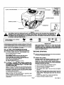
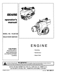
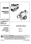
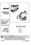
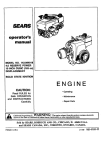
SEARS
operator's
manual
MODE_L NO. 143.991004
SOLID STATE IGNITION
ENGINE
CAUTION:
• Operating
Read RULES for
Safe OPERA:IION
and INSTRUCTIONS
• Maintenance
• Repair Parts
Carefully
A
WARNING: Tho
o._ne
California
Proposition
65
xhaustreproductive
from this product
known to the
State of California
to cause cancer, birth defects oreother
harm. contains chemicals
Sold by SEARS, ROEBUCK AND _O., CHICAGO, IL 60684 U.S.A.
and SEARS CANADA, INC., TORONTO, ONTARIO, CANAD A
Printed in U.S.A.
3-1-9p
181-1192-11
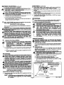
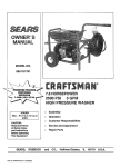
SCREEN
OIL FILL PLUG AND DIPSTICK
MODELAND
D.O.M. DECAL
LEVERS & LINKAGE
SPARK PLUG WIRE
SPARK PLUG'
OIL D
PLUG
MUFFLER
.:
,_IL
Figure 1
PERSONAL SAFETYAND/OR PROPERYT OF YOURSELF AND OTHERS. READAND FOLLOWALL INSTRUCTIONS IN
THIS S'MBOL POINTS OUT IMPORTANTSAFETY INSTRUCTIONS WHICH IF NOT FOLLOWEDCOULDENDANGERTHE ,_hb
, THIS MANUAL AND ANY PROBID_ED.WJTI.i'_TH_.
EqUIpMENT ON WHICH THIS ENGINEIS USEDBEFOREATTEMPTING
TO OPERATEYJ)UR _CRAFTSMAN'
E"NG1NE"
"
" ....
"
....
I,,osoo--O.SM,,,,,,,
ON THE ENGINE:
FAST
®
SLOW
OIL & FUEL RECOMMENDATIONS
OIL.
Be sure original container is marked:
A.P.I. service "SF'=-'SJ".
FOR SUMMER (ABOVE 32°F;0°C) USE SAE 30 OIL
Using muitigrade oil will increase oil consumption.,
FOR WINTER (BELOW 32°F;0=C) USE SAE 5W30 OIL.
(SAE lOW is an acceptable substitute.)
DO NOT USE SAE 10W40 OIL
OIL SUMP CAPACITY: 32 ounces (2 pints).
(_
CHOKE FULL
KEEP THIS MANUAL HANDY AT ALL TIMES FOR FUTURE
REFERENCE. READ IT CAREFULLY AND FAMILIARIZE
YOURSELF WITH THE OPERATING, MAINTENANCE AND
SAFETY INSTRUCTIONS. THIS MANUAL ALSO CONTAINS A
COMPLETE PARTS LISTING.
operate on regular unleaded gasoline. Include the following emission control
system(s): EM, TWC (if so equipped); Do not include any user adjustable
features - therefore no other adjustments are needed
(_ A CLEAN, HIGH QUALITY, DETERGENT
OFF
IMPORTANT
ENGINES WHICH ARE CERTIRED TO COMPLY WITH CALIFORNIA AND
U.S, EPA EMISSION REGULATIONS FOR ULGE ENGINES: Are certified to
TO OPERATE ENGINE, YOU WILL NEED THE FOLLOWING:
mnB
STOP
"BEFORE STARTING
_JJ READALL INSTRUCTIONS PROVIDED WITH THE EQUIPMENT
ON WHICH THIS ENGINE IS USED.
(_) CHECK OIL LEVEL:
CAUTION: NEVER RUN ENGINE UNLESS OIL LEVEL IS
BE'PNEEN "FULL" AND "ADD" MARKS ON DIPSTICK.
CHECK OIL LEVEL OFTEN DURING ENGINE BREAK-IN,
NEVER RUN ENGINE UNLESS OIL RLL PLUG IS TIGHTENED
SECURELY INTO OIL FILL HOLE.
A FRESH.
CLEAN,.94 |iter
UNLEADED
REGULAR,
UNLEADED
PREMIUM,
OR REFORMULATED
AUTOMOTIVE
GASOLINE ONLY. DO NOT USE
LEADED GASOLINE.
A. POSITION EQUIPMENT SO ENGINE IS LEVEL.
B. Clean area around oiltill plug (see Figure 1).
NOTE: DO NOT USE GASOLINE CONTAINING METHANOL
(WOOD ALCOHOL). Gasoline containing up to 10% ethanol or
grain alcohol ("Gasohoi'), or up to 15% M'I'BE (Methyl Tertiary
Butyl Ether), may be used butrequiresspecial care when engine
is unused for extended periods.
C. Remove oil fillplug and dipstick.
D. Wipe dipstick clean, insert it into oil fill hole and tighten
securely.
E. Remove oil till plug and check oil level. If level is not up to
"FULL" mark on dipstick, add recommended oil, until it is.
POUR SLOWLY. Wipe dipstickclean each time oil level is
checked.
Sea "STORAGE" instructionco Page 4.
NOTE: Use clean oil and fuel and store in approved, clean
covered containers. Use clean till funnels.
DO NOT FILL ABOVE "FULL" MARK ON DIPSTICK.
Never use "stale"gasoline leftover from last season or storedfor
long periods.
F. Replace oil tillplug and tighten securely.
Page 1
181-1192-11
BEFORE STARTING (Continued)
STARTING (Continued)
TO ENSURE ADEQUATE OIL SUPPLY:
G. DISCONNECT SPARK PLUG WIRE FROM SPARK PLUG I
I
AND KEEP IT AWAY FROM SPARK PLUG.
_'k
H. Crank engine a few times with starter.
,1_
I
NOTE
NOT USE MOWER
CU'I'I"ING
BLADE OR
OTHER- DO
A'rrACHMENT
ON POWER
TAKE-OFF
ENDANY
OF
CRANKSHAFT TO CRANK ENGINE.
I. Re-check oil level per instructionsC, D, E and F.÷
B. Press starter button or tum ignition switch key per equipment
manufacturer's instructionsto crank engine until it fires.
C. When engine starts move control to FAST and then to RUN
RANGE.
D. If engine falters, move control to CHOKE, then to FAST and then
to RUN RANGE.
NOTE: If engine fires, but does not continue to run, move control
to FAST and crank engine until it starts.
E. If engine still does not start, move control to CHOKE and repeat
instructionsB and C again.
J. Connect spark plug wire to spark plug.
See =MAINTENANCE" section for any future oil level and oil
change instructions(see Page 2).
!
(_
FILL FUEL TAN K withgaso,ne as specified in the preceding
"OIL & FUEL RECOMMENDATIONS," item 2.
NEVER MIX OIL WITH GASOLINE
Move equipment control or any ignitionstop switch on engine to
STOP or OFF (see equipment manufacturer's instructions).
(_ AFTER ENGINE IS STOPPED:
Never use Ustale"gasoline leftover from last season or storedfor
long periods.
NEVER FILL FUELTANKINDOORS. NEVER FILL FUELTANK
WHEN ENGINE IS RUNNING OR HOT. DO NOT SMOKE WHEN
FILLING FUEL TANK.
_
_k
,_A.
DISCONNECT
SPARKFROM
PLUG SPARK
WIRE FROM
AND
KEEP IT AWAY
PLUG.SPARK PLUG
_.
TURN
KEY (IFKEY
SO FROM
EQUIPPED)
TO
"OFF" IGNITION
POSITION SWITCH
AND REMOVE
SWITCH.
THIS
WILL
REDUCE
THE
POSSIBILITY
OF
UNAUTHORIZED
STARTING
OF ENGINE WHILE
EQUIPMENT IS NOT IN USE.
NEVER STORE ENGINE WITH FUEL IN TANK IN DOORS
OR IN ENCLOSED, POORLY VENTILATED AREAS,
WHERE FUEL FUMES MAY REACH AN OPEN FLAME,
SPARK OR PILOT LIGHT AS ON A FURNACE, WATER
HEATER,
CLOTHES
DRYER OR OTHER
GAS
APPLIANCE.
NEVER FILL FUEL TANK COMPLETELY. FILL TANK TO 1/2"
BELOW Bo'rroM OF FILLER NECK TO PROVIDE SPACE
I
.
OPPING
FOR
FUEL EXPANSION.
WIPE
ANY FUEL
SPILLAGE
FROM
ENGINE-AND
EQUIPMENT
BEFORE
STARTING
ENGINE.
_1_ ANY LIQUEFIED PETROLEUM
(LPG) OR NATURAL
GASl
m I-FUEL
S_fSTEMCODES
MUST AND
BE REGULATIONS.
LEAKPROOF AND MEET ALL I
APPLICABLE
(_)
CHECK
_ILA.
THE
FOLLOWING:
MAINTENANCE
_WARN
NG TEMPERATURE OF MUFFLER AND NEARBY
AREAS MAY EXCEED 150°F (650C). AVOID THESE AREAS. J
BE
SURE EQUIPMENT
IS INAND
NEUTRAL
WITH I
CLUTCHES,
BELTS, CHAINS
SAFETYGEAR
SWITCHESI
DISENGAGED.
(FOLLOW
EQUIPMENT I
MANUFACTURER'S INSTRUCTIONS). THIS SHOULD
POSITION.PLACE
ANY SAFETY SWITCHES IN SAFE STARTING
B. Be sure spark plug wire is attached to spark plug (see Figure
1).
C. Be sure any ignitionswitchon angine or equipment is in ON,
RUN or START position.
_.)
CHECK OIL LEVEL:
Check oillevel every five (5) operatinghoursor each time engine
is used. See "2CHECK OIL LEVEL" in "BEFORE STARTING" on
Page 1.
(_
CHANGE
OIL:
Change oil after first two (2) operating hours and every 25
operating hours thereafter, more often if operated in extremely
dusty or dirty conditions.
Chanoe oil while enoine is still warm from recent runnine.
_'
,_A.
STARTING
,_
NEVER RUN ENGINE INDOORS OR IN ENCLOSED, POORLY
VENTILATED
AREAS. ENGINE EXHAUST CONTAINS
CARBON MONOXIDE, AN ODORLESS AND DEADLY GAS
(CARBON MONOXIDE IS ALSO PRESENT IN ENGINE
EXHAUST FROM LIQUID PETROLEUM (LPG) AND NATURAL
GAS FUEL SYSTEMS).
,_
KEEP HANDS, FEET, HAIR AND LOOSE CLOTHING AWAY
FROM ANY MOVING PARTS ON ENGINE AND EQUIPMENT.
,_BE
SURE AIR INTAKE SCREEN (see Fig. 1) IS SECURELY IN
PLACE TO AVOID CONTACT WITH MOVING PARTS.
DISCONNECT
SPARKFROM
PLUGSPARK
WIRE FROM
AND KEEP IT AWAY
PLUG. SPARK PLUG
B. Positionequipment so engine oildrain plug is lowest point on
engine.
C. Remove oil drain plug and oilfill plug to drain oil.
D. Replace oil drain plug and tighten securely.
E. Fill oil sump with recommended oil. See "OIL & FUEL
RECOMMENDATIONS" and "CHECK OIL LEVEL" on Page
I.
F. Replace oil fillplug and tighten securely.
G. Connect spark plug wire to spark plug.
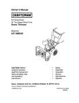
CONTROLBRACKET
CONTROLLEVER- IN FAST
POSITION(HOLE
IN BRACKETIN
LINEWiTH
SLOTON
LEVER)
REMOTECONTROL
_WARNING
TEMPERATURE OF MUFFLER AND NEARBY
AREAS MAY EXCEED 15(PF (65°C). AVOID THESE AREAS.
NOTE:
If angine is mmotely controlled,seeequipmentmanufacturer's
instructionsfor remote controlpositionswhich correspondto
engine control positionsin Figure 2.
ELECTRIC
STARTER
12 VOLT D.C.:
A. Move anglne control lever (see Figure 2) or equipment control to
'_
CHOKE or START.
NOTE:
IF RESTARTING A WA'RM ENGINE, AFTER A SHORT
SHUTDOWN, MOVE CONTROL TO "FAST" INSTEAD
OF "CHOKE."
Page 2
_CHOKE
IDLE
Figure 2
181-1192-1
MAINTENANCE
(_)
(Continued)
MAINTENANCE
(ConUnued)
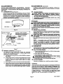
AIR CLEANER:
IMPORTANT: NEVER RUN ENGINE WITHOUT COMPLETE AIR
CLEANER INSTALLED ON ENGINE.
(_ SPARK
This spark ignition system meets all requirements of the
Canadian Interference-Causing EquipmentRegulations. This
engine complies with all current Australian and New Zealand
limitationsregardingelectromagneticinterference.Checkspark
plug yeady or every 100 operating hours.
A. TO SERVICE FILTER(S) (see Figure 3):
1. FOAM FILTER:
Clean and re-oilevery three (3) monthsor every 25 operating
hours. Clean and re-oil daily if used in extremely dusty
conditions.
A. Clean area around spark plug.
S. Remove and inspect spark plug.
C. Replace spark plugif electrodes are pitted,bumed or porcelain
is cracked. For replacement use Champion RJ-19LM or
equivalent.
a.
Wash in water and detergent solution and squeeze
(don't twist) until all dirt is removed.
b.
Rinse thoroughly in clear water.
c.
Wrap in a clean cloth and squeeze (don't twist) until
completely dry.
NOTE: A resistorspark plug must be used for replacemonL
Saturate with engine oil and squeeze (don't twist) to
distributeoil and remove excess oil.
D. Check electrode gapwith wire feeler gauge andset gapat .030
if necessary.
d.
2.
PLUG (see Figure 4):
E. Install spark plug, tighten securely.
PAPER OR FOAM/SCREEN RLTERS:
DO NOT A'rFEMPT TO CLEAN OR OIL FILTER.
ELECTRODES
Replace once a year or every 100 operating hours, more
often if used in extremely dusty conditions.
Replacement filters are available at any nearby Sears
Rcebuck_and Co. (or Seam Canada, Inc.)_ervice Center.
B. TO REMOVE AND INSTALL FILTER(S):
1. Remova wing nuts and cover.
2. Slide FILTER A Off.l_it.TF?l_l
3. Inspect tilter(s) fordiscoloration or dirt accumulation. If either
is present, service per preceding "TO SERVICE FILTER(S)"
instructions.
B.
:
.030 GAP
Figure 4
_)
ALTERNATOR
AND BATTERY
(ifso equipped):
/L ALTERNATOR:
4. Remove nuts and FILTER B. Discard FILTER B and nuts (if
service is necessary).
5. Clean inside of cover and body thoroughly.
6. Install new FILTER B and new nuts. Tighten nuts fingertight
and then turn one (1) more complete turn.
7. Slide foam filter over paper tilter.
8. Install cover and wing nuts. Tighten wing nuts.
WING NUTS
COVER
\
.RLTER A
I_)
For electrical problems such 8s inoperative starter or
dischargedbattery, see your nearbySears Roebuck and Ca.
(or Sears Canada, Inc.) Service Center for fuse replacement
(if so equipped), maintenance and repairs.
B. BATTERY:
1. Whan earvicin9 battery, always connect cablssto battery
exactly as they were before removal (ground cable to
batterynegative [- or neg.] post). If incorrecgyconnected,
alternator won't charge battery. If thishappens, see your
Sears Roebuck and Co. (or Sears Canada, Inc.) Sewise
Center.
2. Never expose engine ignitionsystem to battery power. If
battery cable or any live wire contacts ignition system
groundwire, engine ignition system may be damaged.
3. If external battery charger is used, disconnectpositive(+
or pos.) cable from battery to prevent possibledamage.
4. See battery manufacturer's instructions for service end
storage.
COOLING
SYSTEM;
IMPORTANT: Frequently remove any grass clippings, dirt and
debris from coolingfins, air intake screen and levers and linkage
(see Figures 1 and 5), This will helpensure adequate coolingand
correct engine speed.
AIR INTAKESCREEN
6
FILTER B
(_
_lL
J
Figure 3
Page3
Figure 5
CHECK ENGINE AND EQUIPMENT OFTEN FOR LOOSE NUTSJ
BOLTS AND ATTACHMENTS AND KEEP THESE ITEMS_
TIGHTENED.
/
t81-1192-11
ADJUSTMENTS
ADJUSTMENTS
DO NOT MAKE UNNECESSARY ADJUSTMENTS.
FACTORY
SETTINGS ARE SATISFACTORY FOR MOST APPLICATIONS AND
CONDITIONS. IF ADJUSTMENTS ARE NEEDED, PROCEED AS
_LLOWS:
CARBURETOR
(_
(see Figure 6):
(Continued)
If additional control adjustments are necessary, contact your
nearby Sears Roebuck and Co. (or Sears Canada, Inc.) Service
Center.
If you think your carburetor needs adjusting, see your nearest
SEARS, ROEBUCK AND CO. (OR SEARS CANADA, INC.)
SERVICE CENTER. Engine performance should notbe affected
at altitudes up to 7,000 feet. For operation at higher elevations,
contact your nearest SEARS, ROEBUCK AND CO. (OR SEARS
CANADA, INC.) SERVICE CENTER.
ENGINE SPEED:
FACTORY
SET FOR PROPER
ENGINE
SPEED. l
OVERSPEEDING ENGINE ABOVE FACTORY HIGH SPEED I
SETTING CAN BE DANGEROUS.
I
NEVER TAMPER
WITH ENGINE GOVERNOR
WHICH
ISl
CHANGING
OF ENGINE-GOVERNED
SPEED WILL
VOID
ENGINE WARRANTY.
_
STORAGE
CARBURETOR_
IN ENCLOSED, POORLY VEN'nLATED AREAS, WHERE FUEL I
FUMES MAY REACH AN OPEN FLAME, SPARK OR PILOT I
LIGHT
ON A
FURNACE,
CLOTHES
NEVER AS
STORE
ENGINE
WITH WATER
FUEL IN HEATER,
TANK INDOORS
OR
DRYER OR OTHER GAS APPL ANCE.
_
_
BOWLDRAIN
IF ENGINEISTO BEUNUSEDFOR 30 DAYSOR MORE,PREPARE
_FOLLOWS:
DRAIN FUEL SYSTEM:
Figure 6
CONTROLBRACKET
Remove all gasolinefromcerburetor and fueltank to preventgum
deposits from forming on these parts and causing possible
malfunction of engine.
DRAIN FUEL INTO APPROVED CONTAINER OUTDOORS,
AWAY FROM OPEN FLAME. BE SURE ENGINE IS COOL DO
CONTROL LEVER - IN FAST
POSITION (HOLE IN BRACKETIN
LINE WITH SLOT ON LEVER)
,_
I
NOT SMOKE.
Run engine untilfuel tank is empty and engine stops due to lack
of fuel.
ABLE CLAMP
NOTE:
Fuel stabilizer (such as STA-BIL) is an acceptable
aitemative in minimizing the formation of gum deposits during
storage. Add stabilizer to gasoline in fuel tank or storage
container. Always fallow mix ratio found on stabilizer container.
Run engine at least 10 minutes after adding stabilizer to allow it
to reach carburetor.
LAMP SCREW
_CHOKE
FAST
(_) CHANGE
Change oil if it has not been changed in the last three (3) months.
See "CHANGE OIL" instructions in "MAINTENANCE" section.
Figure 7
(_) REMOTE
CONTROL
OIL CYLINDER
(see Figure7):
Set equipment contro/at FAST or HIGH SPEED and keep in
this position.
B. Loosen clamp screw so remote control cable can be moved
in cable clamp (do not remove cable clamp from control
bracket or disconnect remote control cable from engine
control lever).
BORE:
A. Remove sperkplug. Squirt one (1) oz. (30 ml) of clean engine
oil into spark plug hole.
For satisfactory engine performance, engine and equipment
controls must be adjusted properly. To check engine control
adjustments, proceed as follows:
A.
OIL:
B. Cover spark plug hole with a reg.
C. Crank engine over, slowly, several times.
,_
AVOID SPRAY
CRANKING
ENGINE
FROM
OVER
SPARK
SLOWLY.
PLUG HOLE WHEN I
D. Install spark plug. Do not connect spark plug wire.
(_
CLEAN ENGINE:
Remove any clippings,dirt, or chaff from extedor of engine.
C. Move engine control lover into FAST and hold In thisposition.
D. Tightan clamp screw sscuraly so cable clamp will hold cable
casing in place when equipment control is used. The engine
shouldnow runat the desired speed when equipment control
is set at FAST, and should choke engine when in CHOKE.
GENERAL
Just as yourautomobile needs professionalmechanical maintenance
from time to time, sodoes your Craftsmen engine. Replacement ofthe
spark plug and air cleaner is made necessary by NORMAL use.
Professional Air-Cooled Engine Service is as dose as your nearest
Sears Roebuck and Co. (or Sears Canada, Inc.) Service Center.
A yearly chsck-up or tune-up by Sears is a good idea to avoid
breakdowns or delay.., do it at the end of the season, then you'_re
[eady for the next. We even prepare it for storage for you.
Page 4
181-1192-11
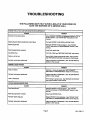
TROUBLESHOOTING
THE FOLLOWING MAY HELP AVOID A DELAY IN YOUR WORK OR
SAVE THE EXPENSE OF A SERVICE CALL.
i ENGINE FALLS TO START OR STARTS WITH DIFFICULTY
CAUSE
REMEDY
Controls not in start position.
Move ENGINE CONTROL or equipment control to "HI" or
START postion. See "STARTING" instructionsin this
manual.
Spark plug wire disconnected from spark plug.
Connect SPARK PLUG WIRE to SPARK PLUG.
Spark plug fouled.
Remove SPARK PLUG and clean it. See "SPARK
PLUG" instructionsin "MAINTENANCE" section In this
manual.
Spark plug porcelain precked÷
Instal! new spark plug.
Insufficientfuel;
Fill FUEL TANI_ per "BEFORE STARTING" instructions.
Water or dirt in fuel.
Drain FUEL TANK end re-fill with clean, fresh gasoline.
See "BEFORE STARTING" instructionsin this manual.
Impropercarburetoradjustment
Adjust carburetor (if applicable). See "ADJUSTMENTS"
section in this manual.
ENGINE LACKS POWER
CAUSE
REMEDY
Dirtyair cleaner.
Replace or clean air cleaner per 'AIR CLEANER"
instructions in "MAINTENANCE" section in this manual.
Improper carburetor adjustment.
Adjustcarburetor (ifapplicable).See 'ADJUSTMENTS"
sectionin thismanual.
Lack of lubricaiton.
Fill oil sump to proper level. See "BEFORE STARTING"
instructionssection in this manual.
..
ENGINE MISSES UNDER LOAD
CAUSE
REMEDY
Spark plug fouled.
Remove SPARK PLUG and clean it. See 'SPARK
PLUG" instructionsin "MAINTENANCE" section in this
manual.
Sparkplugporcelaincracked.
In=allnew SPARK PLUG.
Impropersparkpluggap.
Regap SPARK PLUG electrodes. See "SPARK PLUG'
instnJctlonsin "MAINTENANCE" section in this manual.
Improper carburetor adjustment
Adjust carburetor (if applicable). See "ADJUSTMENTS"
section in this manual.
Page 5
181-1192-11
SEARS, ROEBUCK AND CO.
Federal
and California
Utility
Emission
and Lawn
Control Systems Limited
and Garden Engines
CALIFORNIA & US EPA EMISSION CONTROL
WARRANTY STATEMENT
The U. S. En_ronmental Protection Agency {'EPA"), the California Air Resources
Board ('CAR B") and Sears, Roebuck and Co. am pleased to explain the Federal and
Caltfomla Emission Control Systems Warranty on your new utility or lawn and garden
equipment engine. In Calltomle, new 1995 and later utll'dll,y
and lawn and garden
equipment engines must be designed, builtand equipped te meet the State's
stdngent anlt-smng standards. In other states, new 1997 and later modal year
engines must be designed, built and equipped, at the tme of sale, to meet the U.S.
EPA regulations for small non-r_ad engines. Sears, Roebuck and Co. willwarrant
the emission conta_ system on your utilityor lawn and garden equipment engine for
the periods of time listed below, provided there has been no abuse, neglect.
unapwoved modltk:aticn, or improper malnter_nce of your utilityor lawn and garden
equlpment engine.
Warranty
B. GENERAL EMISSIONS WARRANTY COVERAGE: Seam, Roebuck and CO.
warrants to the original, end.use purchaser of the new engine ot equipment and to
each subsequent purchaser that each of its utility and lawn and garden equipment
engines is:
1. Designeq, builtand equipped so as te conform with all applicabla regulations
adopted by the Air Resources Board pursuant to its authority in Chapters 1
and 2, Part 5, DMsion 26 of the Heaffh and Safety Code, and
2. Free flora defects in materials and workmanship whk;h, at any time dud_ the
ECS Warranty Pedod, will cause a warranted emP'_sions-ndatedpart to fall to
he identical in all matedal respects to the pad as described in the engine
manufacturefs appltcaben for certification.
C, The ECSWarrantyonlypertainsto emissions-related
dartsonyourengine,as
follows:
Your emission control system may k_clude ports such _ the carburetor, ignition
system and exhaust system. Also instuded may be the compression release system
and other emlaskm-mlated assembles.
1. Anywan'anted,er_sslans-related
partswhich ate natscheduledfor
replacementas requiredmaintenanceIn theOwner'sManualshaltbe
warrantedforthe ECSwarrantyPeriod.if any suchpadfailsduringthe ECS
WanantyPabod,if shallbe redalredor replaceqby Sears,RoabuckandCO.
accordingtoSubeecton4 beinw. Any suchpartrepa!reqor rabtecedunder
theEC3 Warrantyshallbe warrantedforany remainderoftheECSWarranty
Period.
Where a warrantable condition exists, Sears, Roebuck and Co. will repair your utility
c_ lawn and garden equipment engine at no cost to you for diagnosis, parts and labor.
MANUFACTURER'S EMISSION CONTROL SYSTEM
WARRANTY COVERAGE
2. Any warranted, emisalons-ralateq gart which is sofleduleq only for regular
I_
_ I_pedfled in the Owner's Manual shall be watmated foe the ECS
Warr_
Pabed. A mtement ta _ch wriften _
to the effeof of
"re_
or reptece as necess_y', shall not reduce the ECS Warranty Pedod.
Any sush pad repalreq or replaced under the ECS Wan-anty shstl be
wananteq for the rernalndet of the ECS Warranty Pedod.
Emlaalon contrbl systems on 1995 and later modal year Caltomla ofilty and tawn and
ga,-den equipn_nt engines am wananteq tee two yearn as beminafter noted, in other
states. 1997 andlater modalye_'engthes,, am alsowarraateq for two years, if, during
such wananty bedod, any em,..ss_on-mlatedpad on your engine is dafectve in
matedale or workmanship, the part will be repaired o_"teqlaced by S_us, P,oabuck
and CO.
3. Anywarranteq,emlaalons-rstated
bert whkthisschedofedforreplacemantas
requiredmaintenanceintheOwner'sManual,shallbe warrantedforthe
bedodof tane WIorte thetirstscheduledreplacementgairdfor _at parL If the
parHallspriortothe firstscheduladreplacement,the partsh_ be mpeired or
replacedby Sears,RoebuckandCO.accordingtoSubsection4 below. Any
oucher!!salons-related
part repairedor replacedundattheECSWarranty,
shallbe warrantedforthe remainderoftheECS WarrantyPerladpriortothe
firstscheduledreplacementpointforsuchemisalons-ralateq
part.
OWNER'S WARRANTY RESPONSIBILITIES
As the utti_'or lawn and garden equipment engine owner, you are responsible for the
rlarmance of the required maintenance r_sted in your Owner's Manual, but Sears,
_: _eo_uck aed CO. will not deny warranty solely due te the lack of recstpta or fo_your
failure to provide written evidence of the performance of all scheduled maintenance.
As the utilityor lawn and garden equipment engine owner, you should, however, be
aware that Sears, Roebuck and Co. may deny you warranty coverage if your utility
or
lawn and garden equipment or a part thereof has fallad due to abuse, negleof,
improper maintenance or unepproved modifications.
4. Repair or replacement of any warranted, emisalons-ralateq part under thle
ECS Warranty shall be performed at no charge to the owner at a Sears,
Roebuck and Co. Authorized Setvioe OutlaL
You are respor_siblafor beDsentng your utilityor lawn and garden equlpmest engine
to a Sears, Roebuck and Co. Authorized Setvtae Outlet as soon as a problem exists.
The warranty repairs should be completed in a reasonable amount of time, n_ to
exceed 30 days.
5. The owner shall not be chergad for dlagnostta labor which laeds to the
dsterminatla_ that aapartcoveredby the ECS Wanandy is in fact defective,
provided that such diegno_tc workis pedorrned at a ,_ears, Roebuck and Co.
Authodzed Service Outlet.
Warranty ser_ce can be ananged by contacting either a Sears, Roebuck and Co.
Authorized Service Outlet, or by contacting Sears, Roebuck and Co. at 1-800-4737247.
6. Sears, RoebuckandCo. shellbe liablefordamagesto otheroriginalengine
components
or approvedmodificationspro_dmataly
causedby a failure under
warranty
ofanemlsalon-related
part
coveredbytheECS Warranty.
IMPORTANT NO'RE
7. Throughout the ECS Warranty Period, Seam, R_b_ck and Co. shall rnalntaln
a supply of warranted erblsalo_-related parts surf'dent to meet the expected
demand for such emisalo_-related parts.
This warranty statement explains your rights and obl_a_ons under the Emission
Control System Warran_ ('ECS Warranty") which is provided to you by Sears,
Roebuck and Co. pursuant to California law. S_e also the Sears, Roebuck and Co.
Umiteq Warranties for Sears, Roebuck and Co. which is enclosed therewith on a
separste sheet and also is provk_ to you by Seers, Roequck and Co. Tbe ECS
Warranty abplles only to the emisalon conth_l system of you,"new engine. Totbe
extent that there is any conflict in terms between the ECS WaNananty
and the Sears,
Roebuck and CO.Warranty, the ECS Warranty shall apply excab_ in any circumstances in which the Sears, Roebuck and Co. Wan an_ rnay _
a ldnger warranty
period. Both the ECS Warranty and the Sears, Roabuck and CO. Warranty describe
importent rights and obligations.wlthrespect to your new engine.
Warranty service can only be performed by a Sears, Roebuck and CO.Authorized
Service Outlet. At the time of requesting warranty sewice, evidence must be
presented of the date of sale to the original pumhaser. The purchaser shall pay any
charges for maldng service ca,s and/or for transpo_ng the products to and fTOmthe
place whom the inspection and/or warranty wed_ is bet foctned. The p_chaser shall
De responsible for any damage or loss incurred in connection with the transportation
of any engine or any pstt(s) thereof supm_ed fo_inspeclto_ angler warranty work.
8. Any Sears, Roebuck and CO. authodzeq and abp
ed emisston-relateq
reglacemeat pad ma;/be used in the berfonnanoe of any ECS Warraaty
maintenance or raba_rand will be prm_bed w_hout charge to the owner. Such
use shall not reduce Sears, Roebuck and Co. ECS Warranty ob_lgaltons.
9. Unapproved odd-on or modltied parts may not be used to mndlty or repair a
Sears, Roebuck and Co. engine. Such use voids this ECS Warranty and shall
be sufficient grounds for disallowing an ECS Warranty claim. Seam, Roebuck
and CO. shall not be Ilabla hereunder for failures of any warranted parts of a
Seam, Roebuck and Co. engine caused by the use of such an unapproved
odd-on or modlhnd pad.
EMISSION-RELATED
PARTS INCLUDE THE FOLLOWING:
1. Carburetor Assembly and its Internal Components
Cerbundor
gaskets
! Fual
tilter
Intake
pipe
If you have any questons regardingyour warranty rights and respenall_ltbes, you
should contact Sears, Roebuck and Co. at 1-800-473-7247.
2. Air Cleaner Assembly
a) Air filter element
EMISSION CONTROL SYSTEM WARRANTY
3. ignition System, inblud_:
a) spe_pl.g
Emtas_n Control System Warranty ('ECS Warranty_ for 1995 and later model year
Calif c<nlautility and lawn and garaen equipment engines (for other states, t 997 and
later model year entries):
b I niton module
A. APPLICABILITY: This warrant'/shall apply to 1995 and later model year
California utllty and lawn and gamen equipment engines (for other states, 1997 and
later modal year en_nes). The ECS Warrant'/Period shall begin on the date the new
engine or equipment Is deliVered to its odginal,
end-use purchaser and shall continue
for 24 consecutive months thereafter.
4. Cota.lyUc Muffler Of so eqUil_Oed)
a Mufflar gaskst 0f so equtobeo)
b Exhaust manifold (tiso equipped}
5. Crankcase Breather Assembly and its Components
a) Breather conneofkm tabe
7,22.97 E_A_ARB
Sears, Roebuck and Co., Hqffman Estates, IL 60179
Page 6
U.S.A.
181-1192-1!
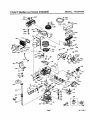
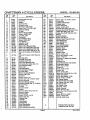
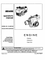
CRAFTSMAN
4-CYCLE ENGINE
MODEL:143.991004
i _......_298
263
347
e.......-93
,258
286
29o<_
234
262
261
.240
238
_,,.,,.325B
_t325A
18
280
151
126
40
277
41
395
j_
Page 7
181-1192-11
CRAFTSMAN
Ref.
No.
Part
No.
1
2
14
15
16
17
18
19
20
25
26
28
30
31
35
36
37
38
4O
4O
4O
41
41
35421
27652
28277
35082
36494
29916
651028
36495
35319
35424
650561
30322
35429A
35327
29826
29918
29216
29642
35776A
35777A
35778A
"35773A
, 35774A
41
35775A
42
42
42
43
45
47
48
5O
51
52
6O
62
63
65
66
68
69
7O
72
75
8O
81
82
83
84
86
88
89
9O
92
93
100
101
102
35779
35780
35781
35772
36895
651033
34034
35381
35315A
31356
33273A
650760
28545
650128
650990
33356
*35317
35711A
31927
35319
35783
30590A
35378
30588A
29193
650833
31707A
32589
611093
650880
650881
35135
610118
651024
4-CYCLE
ENGINE
Part Name
Cylinder (Incl. 2 & 20)
Dowel Pin
Washer
Governor Rod
Governor Lever
Governor Lever Clamp
Screw, Torx %16, 8-32 x 3/8"
Extension Spring
-_
Oil Seal
Blower Housing Baffle
Screw, 1/4-20 x 5/8"
Lock Nut, 8-32
Crankshaft
Counterblance Gear
Screw, 10-32 x 3/4"
Lock Washer
Lock Nut, 10-32
Retaining Ring
Piston, Pin & Ring Set (Std.)
Piston, Pin & Ring Set (.010" OS)
Piston, Pin & Ring Set (.020" OS)
Piston & Pin Ass'y. (Std.) (Incl. 43)
Piston & Pin Ass'y. (.010" OS) (Incl.
43)
Piston & Pin Ass'y. (.020' OS) (Incl.
43)
Ring Set (Std.)
Ring Set (.010" OS)
Ring Set (.020" OS)
Piston Pin Retaining Ring
Connecting Rod Ass'y. (incl. 47)
Connecting Rod Bolt
Valve Lifter
Camshaft (MCR)
Counterbalance Weight
Oil Pump Ass'y.
Blower Housing Extension
Screw, 8-32 x 3/8"
Grommet
Screw, 10-24 x 1/2"
Screw, TorxT-30, 1/4-20 X 15/32"
Greund Terminal
Mounting Flange Gasket
Mounting Flange (Incl. 72, 75 & 80)
Oil Drain Plug
Oil Seal
Governor Shaft
Washer
Governor Gear Ass'y. (Incl. 81)
Governor Spool
Retaining Ring
Screw, 1/4-20 x 1-3/16"
Spacer (Incl. 8!)
Flywheel Key
Flywheel
Lock Washer
Flywheel Nut
Solid State Ignition
Spark Plug Cover
Solid State Mounting Stud
MODEL:143.991004
Ref.
No.
103
110
119
120
123
124
125
125
126
126
127
128
130
135
149
149A
150
151
169
170
171
172
173
174
178
182
184
185
186
200
203
204
207
209
210
211 ',
223
224
234
238
239
240
245
245A
250
251
260
261
262
263
264
264A
265
Pad
No.
Pad Name
651007
Screw, Torx T-15, 10-24 x 15/16"
35234
Ground Wire
*36451
Cylinder Head Gasket
36449
Cylinder Head
33261
Intake Pipe Brace
651031
Screw, 1/4-20 x 9/16"
27878A
Exhaust Valve (Std.) (Incl. 151)
27880A
Exhaust Valve (1/32" OS) (Incl. 151)
34035
Intake Valve (Std.) (Incl. 151)
34036
Intake Valve (1/32" OS) (Incl. 151)
650691
Washer
650690
BelleviUe Washer
650694A
Screw, 5/16-18 x 2"
33636
Resistor Spark Plug (RJ17LM)
27882
Valve Spring Cap
35862
Valve Spdng Cap
27881
Valve Spring
32581
Valve Spdng Keeper
"27896A
Valve Cover Gasket
28423
Breather Body
28424
Breather Element
28425
" Valve Cover
35350
Breather Tube
650128
Screw, 10-24 x 1/3"
29752
Nut & Lock Washer, 1/4-28
30088A
Screw, 1/4-28 x 1°
*33263
Carburetor To Intake Pipe Gasket
34926
Intake Pipe
33860
Governor Link
35956
Control Bracket (Incl. 203 & 204)
36482
Compression Spring
650777
Screw, 6-32 x 21/32"
35989
Choke Link
650902
Screw, 10-32 x 7/16"
27793
Conduit Clip
28942
Screw, 10-32 x 318"
650378
Screw, Torx %30, 5/16-18 x 1-1/8"
"27915A
Intake Pipe Gasket
650825
Nut & Lock Washer, 1/4-20
650834
Screw, 10-32 x 1-17/32"
"33629
Air Cleaner Gasket
35538B
Air Cleaner Body (Incl. 239)
35403
Air Cleaner Filter (Incl. 234)
35404
Air Cleaner Filter
35961
Air Cleaner Cover
650886
Wing Nut, 1/4-20
36266
Blower Housing
650788
Screw, 5/16-18 x 3/4"
29747B
Screw, Torx T-40, 5/16-24 x 21/32"
35963
Trim Ring
650990
Screw, 5/16-18 x 15/32"
650802
Screw, 1/4-20 x 5/8"
33272B
Cylinder Head Cover
*Indicates Parts Included in
Gasket Set, Ref. No. 400.
Page 8
181-1192-11
CRAFTSMAN
Ref.
No.
Part
No.
276
40003
276
277
281
282
286
290
292
298
300
301
305
307
308
310
314
315
31588
650729
33013
650760
35962
30705
26460
28763
33583B
36246
35574
35499
35437
35576
650873
611113
321
332
323
324
325
4-CYCLE ENGI N E
Part Name
I Muffler
Locking Plate
Screw, 5/16-18 x 3-3/16"
Starter Bubble Cover
Screw, 8-32 x 3/8"
Cup & Screen
Fuel Line
Fuel Line Clamp
Screw, 10-32 x 35/64"
Fuel Tank (loci. 292, 298 & 301 )
Fuel Cap
Oil Fill Tube
"O" Ring
RII Tube Clip
Dipstick
Screw, 1/4-20 x 3/4"
Alternator Coil (3 Amp) (IncL 321 323)
611161
Diode
610921
Connector Body
610922
Terminal
33177--_ .Tdm)inaP_
29443... : .Wire'Cltp
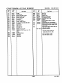
MODEL:143.991004
Ref.
No.
Part
No.
325A
27275
34246
36210
650949
35274
640091A
650948
36680
325B
326
347
370G
380
394,6,
395
400
416
900
900
Part Name
Wire Clip
Wire Clip
Screen Plug
Screw, 10-32x9/16"
Oil Instruction Decal
Carburetor (Incl. 184)
Washer
Electdc Starter Motor (12 Volt)
(Optional)
36452A
Gasket Set (Incl. Items Marked *)
34479A
Spark Arrestor Screen Kit (Optional)
Replacement Engine 752329, order
from 71-999
Replacement Short Block 752312A,
order from 71-999
181-1192-11 Operator's Manual
*Indicates Parts Included in
Gasket Set, Ref. No. 400.
RPM High 3250 to 3550
RPM Low 2000 to 2300
!
!
Page 9
181-1192-11
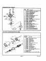
CARBURETOR
NO. 640091A
Ref.
No.
1
2
4
5
6
7
10
11
12
13
14
18
17
18
20
20A
25
27
28
29
30
31
36
37
4O
44
47
48
6O
2o L 2o
4s__
27
Yx37
J,//"
STARTER
_'_36
/
@
ELECTRIC
////
25
Pert
No.
Part Name
640091A
631776A
631970
*631184
"63t 183
640109
*650506
632580
632473
"631184
*631183
631881
632527
651025
630766
640027
64OO53
631887
*631024
632019
*631028
*631021
631022
640113
"632547
640128
27110A
"630748
*631627
632760
Carburetor (Incl. 184 of Engine Parts List)
Throttle Shaft & Lever Assembly
Throttle Retum Spdng
Dust Seal Washer
Dust Seal ('l'hmttle)
Throttle Shutter
Shutter Screw
Choke Shaft & Lever Assembly
Choke Return Spdng
Dust Seal Washer
Dust Seal (Choke)
Choke Shutter
Fuel Fitting
Throttle Crack Screw/Idle Speed Screw
Tension Spdng
Idle Restdctor Screw
Idle Restdclor Screw Cap
Float Bowl
Roat Shaft
Float
Float Bowl "O" Ring
Inlet Needle, Seat & Clip (Incl. 31)
Spdng Clip
Main Nozzle Tube
"O" Ring, Main NozTJe Tube
High Speed Bowl Nut
Bowl Nut Washer
Welch Plug, Idle Mlxtum Well :
Welch Plug, Atmospheric Vent
Repair kit (Incl. Items Marked *)
Part
No.
Part Name
MOTOR NO. 36680
i Ref.
No.
15
L
1
2
3
4
5
6
7
8
9
10
12
14
15
16
36680
33451
33842
33430
33854
33432
35893
33450
35894
35895
36699
35896
35897
35898
35899
17
18
20
65016_
650864
650990
Electric Starter (12 Volt)
Dust Cover
Retainer Ring
Spring Retainer
Anti-driftSpring
Gear
Nut & Retainer (Incl. No. 2)
Lock Nut
Ddve End Cap Ass'y
Armature
Housing Ass'y
Brush & Spdng Kit
Thrust Washer
Bolt, 10-32 x 4-11/64"
End Cap & Brush Card Ass'y (Incr.
12, 14, 17& 18)
Washer
Nut
Screw, Torx T-30, 1/4-20 x 15/32
i
Page 10
181-1192-11
How to ORDER Repair Parts
The Model Number can be found on a decal on the blower housing
(See Figure 1). Always mention the Model Number when requesting
service or repair parts for your Craftsman Engine.
SEARS
All parts listed herein may be ordered from any SEARS, ROEBUCK
AND CO. or SEARS CANADA, INC. retail or catalog store. If the
parts you need are not stocked locally,your order will be electronically transmitted to a Sears Repair Parts DistributionCenter for
expedited handling.
operator's
manual
WHEN ORDERING REPAIR PARTS, ALWAYS GIVE THE FOLLOWING INFORMATION AS SHOWN IN THIS LIST.
1. The PART NUMBER
2.
The PART DESCRIPTION
.°_
3. The MODEL NUMBER
-4.
The NAME OF ITEM - ENGINE
MODEL NO. 143.991004
SOLID STATE IGNITION
CAUTION:
Read RULES for
Safe OPERATION
and INSTRUCTIONS
Carefully
"Your Sears merchandise has added value when you consider that Sears has
se_ce units nationwide staffed with Sears trained technicians.., professional
technicians specifically trained on Seam products, having the parts, tools and
equipment to insurethat we meet our pledge to you ... we servicewhat we selL"
Sold by SEARS, ROEBUCK AND CO., CHICAGO, IL 60684 U.S.A.
and SEARS CANADA, INC., TORONTO, ONTARIO, CANADA
181-1192-_11