1
MITSUBISHI
THE BIG SCREEN
COMPANY
TM
RISK OF ELECTRIC SHOCK
DO NOT OPEN
CAUTION:
TO REDUCE THE RISK OF ELECTRIC
(OR BACK).
NO USER-SERVlCEABLE
REFER SERVICING
SHOCK,
DO NOT
REMOVE COVER
PARTS INSIDE.
TO QUALIFIED
SERVICE PERSONNEL.
/_The
the user
lightning
to the
flash
presence
with arrowhead
of uninsulated"dangerous
symbol within anvoltage
equilateral
within
triangle
the products
is intendedenclosure
to alert
that may be of sufficient magnitude to constitute a risk of electric shock.
//_
The
presence
exclamation
of important
point operating
within an and
equilateral
maintenance
triangle(servicing)
is intendedinstructions
to alert thein user
the literature
to the
accompanying the appliance.
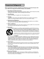
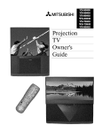
Warning:
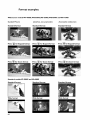
To avoid permanently imprinting a fixed image onto yourTV screen, pleasedo not display the same
stationary images on the screen for more than 15%of your total TV viewing in one week. Examplesof stationary
images are letterbox top/bottom bars from DVD disc or other video sources,side bars when showing standard TV
pictures on widescreen TV's, stock market reports, video game patterns, station logs, web sites or stationary computer images. Such patterns can unevenly agethe picture tubes causing permanent damageto theTV. Pleasesee
page 56 for a detailed explanation.
Note: This equipment has been tested and found to comply with the limits for a Class B digital
device, pursuant to part 15 of the FCC Rules. These limits are designed to provide reasonable
protection against harmful interference in a residential installation. This equipment generates, uses
and can radiate radio frequency energy and, if not installed and used in accordance with the instructions, may cause harmful interference to radio communications.
However, there is no guarantee that
interference will not occur in a particular installation.
If this equipment does cause harmful interference to radio or television reception, which can be determined by turning the equipment off and on,
the user is encouraged to try to correct the interference by one or more of the following measures:
• Reorient or reJocate the receiving antenna
• Increase the separation between the equipment
and receiver
• Connect
the equipment
into an outlet on a circuit different from
that to which the receiver is connected
• Consult the dealer or an experienced
radio/TV
technician for help
Changes or modifications
this equipment.
not expressly approved by Mitsubishi could void the user's authority
WARNING:
TO REDUCETHE RISK OF FIREOR ELECTRIC SHOCK, DO NOT EXPOSETHISAPPLIANCETO
MOISTURE.
to operate
RAIN OR
CAUTION:
TO PREVENT ELECTRIC SHOCK, MATCH WIDE BLADE OF PLUGTO WIDE SLOT,FULLY INSERT.
NOTE TO CATV SYSTEM INSTALLER:
THIS REMINDER IS PROVIDEDTO CALLTHE CATV SYSTEM INSTALLER'SATTENTION TO ARTICLE 820-40 OF
THE NEC THAT PROVIDESGUIDELINES FOR PROPERGROUNDING AND, IN PARTICULAR, SPECIFIESTHAT
THE CABLE GROUND SHALL BE CONNECTEDTOTHE GROUNDING SYSTEM OFTHE BUILDING,AS CLOSE
TOTHE POINT OF CABLE ENTRYAS PRACTICAL.
Contents
Important
Safeguards
5
Instructions on safety and proper handling of your Mitsubishi television
Special
Features
7
Distinctive features, items included with your Mitsubishi television and hookup guidelines
Shortcuts
8
A quick reference list
Connections
9
Basic hookups to an antenna, cable, components, IR emitter and HDTV receiver
Remote
Control
Functions
18
Features of the remote control, programming to work with other audio and video products,
explanation of buttons, controlling the sleep timer
The
I_l_Menu
System
25
Explanation of the on-screen menu system and all menu screens and how to use the menus
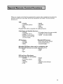
Special
Remote
Control
Functions
59
Using the remote with other products, using the PIP (Picture-in-Picture), Side-by-side
and POP (Picture-outside-Picture)
features, Formats, Mitsubishi's Active AV Network
and Home Theater IR system control
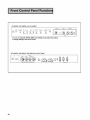
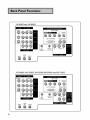
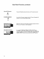
Control
Panel
Functions
68
Explanation of the front control panel buttons and the back panel terminals
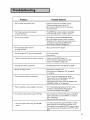
Troubleshooting
Common
73
problems, notes on caring and cleaningfor your Mitsubishi television and how to obtain
service
Appendices
Diamond Shield TM removal and installation, remote control programming codes, bypassing
the parent lock, INPUT-3 component video and HDTV video connection compatibility
77
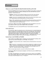
Please read all these instructions regarding your television set and retain for future
ence. Follow all warnings and instructions marked on the television.
refer-
I.
Read, Retain and Follow Instructions
Read alt safety and operating instructionsbefore operating the appliance. Retain the safety and operating
instructionsfor future reference. Follow all operating and use instructions.
2.
Heed Warnings
Adhere to alt warnings on the applianceand in the operating instructions.
3.
Cleaning
Unplug this TV receiver from the wall outlet before cleaning. Do not use liquid or aerosol cleaners.
Cleaners can permanently damagethe cabinet or screen. Use a damp cloth for cleaning.
4. Attachments
and Equipment
Never add any attachments and/or equipment without approval of the manufacturer as such additions
may result in the risk of fire, electric shock or other personal injury.
5. Water and Moisture
Do not usethis TV receiver where contact with or immersionin water is possible. Do not use near bath
tubs, wash bowls, kitchen sinks, laundry tubs, swimming pools, etc.
6. Accessories
Do not place this TV receiver on an unstable cart, stand,tripod, bracket, or table. The TV receiver may
fall, causing serious injury to a child or adult, and serious damageto the appliance. Use only
with a cart, stand,tripod, bracket, or table recommended by the manufacturer,or sold
with the TV receiver. Any mounting of the appliance should follow the manufacturer's
instructions,and should use a mounting accessory recommended by the manufacturer.
@
An applianceand cart combination should be moved with care. Quick stops, excessive
force, and uneven surfaces may cause the applianceand cart combination to overturn.
7. Ventilation
Slots and openings in the cabinet are provided for ventilation and to ensure reliable operation of theTV
receiver and to protect it from overheating. Do not block these openings or allow them to be blocked
by placing the TV receiver on a bed,sofa, rug,or other similar surface. Nor should it be placed over a
radiator or heat register. If the TV receiver is to be placed in a rack or bookcase, ensure that there is
adequate ventilation and that the manufacturer's instructionshave been adhered to.
.
.
Power Source
ThisTV receiver should be operated only from the type of power source indicatedon the marking label.
If you are not sure of the type of power supplied to your home, consult your appliance dealer or local
power company.
Grounding or Polarization
ThisTV receiver is equipped with a polarized alternating current line plug havingone blade wider than
the other. This plug will fit into the power outlet only one way. If you are unable to insert the plug fully
into the outlet, try reversing the plug. If the plug should still fail to fit, contact your electrician to replace
your obsolete outlet. Do not defeat the safety purpose of the polarized plug.
I O. Power-Cord
Protection
Power-supply cords should be routed so that they are not likely to be walked on or pinched by items
placed upon or against them, paying particular attention to cords at plugs, convenience receptacles, and
the point where they exit from the appliance.
I I. Lightning
For added protection for thisTV receiver during a lightningstorm, or when it is left unattendedand unused for
longperiods of time, unplug it from the wait outlet and disconnect the antenna or cable system. This will prevent
damageto theTV receiver due to lightning and power-line surges.
12. Power Lines
An outside antenna system should not be locatedin the vicinity of overhead power lines or other electric light
or power circuits, or where it can fall into such power linesor circuits. When installingan outside antenna
system,extreme care should be taken to keep from touching such power lines or circuits as contact with them
might be fatal.
13. Overloading
Do not overload wait outlets and extension cords as this can result in a risk of fire or electric shock.
14. Object and Liquid Entry
Never push objects of any kind into this TV receiver through openings as they may touch dangerous voltage
points or short-out parts that could result in a fire or electric shock. Never spill liquidof any kind on theTV
receiver.
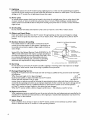
15. Outdoor Antenna
Grounding
If an outside antenna or cable system is connected to the TV
receiver, be sure the antenna or cable system isgrounded so as
to provide some protection againstvoltage surges and built-up
static charges.
EXAMPLE
OF ANTENNA
GROUNDING
LEAD
GROUND
CLAMP
IN WkRE
ANTENNA
ANTENNA
(
DISCHARGE
Section 810 of the National Electrical Code,ANSI/NFPA No. 701984,provides informationwith respect to proper grounding of
the mast and supporting structure, grounding of the lead in wire
to an antenna discharge unit, size of grounding conductors,
locationof antenna discharge unit, connection to grounding
electrodes, and requirements for the grounding electrode.
UNiT
GROUNDING
CONDUCTORS
(NEC
(NEC
SECTkON
SECTION
OUND
_ _"'_'_"_,_
p OWE R SERVICE
ELECTRODE
NEC
._ NATkONAL
ELECTRICAL
CODE
(NEC
ART
8_0-21)
8_0-20)
CLAMPS
GROUNDING
SYSTEM
250,
PART
H)
16. Servicing
Do not attempt to service this TV receiver yourself asopening or removing covers may expose you to dangerous voltage or other hazards. Refer atl servicing to qualified service personnel.
17. Damage Requiring Service
Unplug this TV receiver from the walloutlet and refer servicing to qualified service personnel under the following conditions:
(a)
When the power-supply cord or plug is damaged.
(b) If
liquid has been spilled, or objects havefallen into theTV receiver.
(c) If theTV
receiver has been exposed to rain or water.
(d) If theTV
receiver does not operate normally by following the operating instructions,adjust onty those controls that are
covered by the operating instructionsas an improper adjustment of other controls may result in damageand witl
often require extensive work by a qualified technician to restore theTV receiver to its normal operation.
(e) If theTV receiver has been dropped or the cabinet has been damaged.
(f)
When theTV receiver exhibits a distinct change in performance -- this indicatesa need for service.
18. Replacement
Parts
When replacement parts are required, be sure the service technician has used replacement parts specified by the
manufacturer or have the same characteristics as the original part. Unauthorized substitutions may result in fire,
electric shock or other hazards.
19. Safety Check
Upon completion of any service or repairs to this TV receiver, ask the service technician to perform safety
checks to determine that the TV receiver isin safe operating condition.
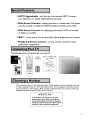
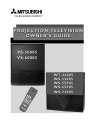
0 HDTV
Upgradeable
your television
0Wide
ratio
- with the use of an optional
can display High Definition
Screen
Television-
for models
displays
0 IRIS
TM
audio/video
in a widescreen
anamorphic
- room sensor that automatically
0 Multibrand
The following
pictures
displaying
Remote
Control
receiver,
pictures
WT-46805,WS-55805,WS-55905,WS-65905
0Wide
Screen
Formats-for
VS-50805 and VS-60805
HDTV
16:9 aspect
andWS-73905
DVDs
on models
adjusts brightness
- use one remote control
and contrast
for many
components
items are included with your newTV:
b
2 AAA
O
Active A/V Network Cable
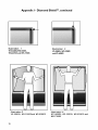
Dialnond
Shiekd (may
aiready
be _nst akled )
batteries
IR Emitter Cable
The connections shown in this book are general. Cable systems as well as individual audio and/
or video components can vary from those shown here. The first diagrams show basic connections to antenna or cable systems. After you have completed these, you can then connect any
additional components (stereo, DVD, AV receiver, etc.).
IMPORTANT
To maximize
your system for its best
performance,
your dealer can help you
customize hookups and sell you any additional connection
accessories that may be
needed for your individual equipment.
0 Connecting
theTV
0 Connecting
an HD-1080
0 Remote
control
to an antenna
functions
0 Menu
screen summaries
0 Setup
Menu
0 Setting
receiver
cable
- page 15
- pages 18-19
- pages 26-28
- pages 29-35
theV-Chip
parent
lock - pages 44-48
0 Using PIP and POP features
0Troubleshooting-
page 73
0 DVD
video
component
compatibility
or wall outlet
- page 83
- page 60
and HDTV
video connection
- page 9
TV to Antenna
Separate
UHF
andVHF
or Wall
Outlet
Cable
antennas
I, Connect the UHF andVHF
antenna leads to the UHF/VHF
combiner,
VHF A_te_na
(Chanr_ls
UHF Antenr_a
2-_3)
(Ch_nels
14_69)
TVback
2, Push the combiner onto ANT-A
on the TV back panel.
Back
Twin lead antenna
For antenna
or wall outlet
panel
SUe
cable
with twin flat leads
I. Connect the 300 ohm twin leads
to the transformer.
TV back panel
2. Push the 75 ohm side of the
transformer onto ANT-A on the
TV back panel.
For cable or antenna
coaxial lead
lwln Le_d
30O Ohm FF_t
with
_
Connect the incoming cable
to ANT-A on the TV back
panel.
Olxiona_ 30O Oh_ _o75 Ohm
M_tch_ T_ansfc_me_
Connection
of TV to Cable Box
I. Connect the incoming cable to
ANT-A on the TV back panel.
2. Connect two coaxial cables as
follows:
• One from LOOP-OUT
TW_d¢_
mln_
on theTV
back panel to IN on the back of
the cable box.
• One from OUT on the back of
the cable box to ANT-B on the
TV back panel.
9
Connection
of TV to VCR and Cable Box
I. Connect the incoming cable toANT-A
on theTV back panel.
2. Connect three coaxial cables as fol{ows:
• One from LOOP-OUT on theTV back
panel to IN on the back of the cable
box.
• One from OUT on the back of the
cable box toANTENNA
IN on the
VCR back panel.
R_
• One from ANTENNA
Ten_nar_
OUT on the
VCR back panel to ANT-B on the TV
back panel.
Audio Video
Connections
I. Connect a video cable from VIDEO,
OUT on theVCR back panel to VIDEO,
INPUT-I or INPUT-2 on theTV back
panel.
If you have a S-VHS VCR, follow the
same steps, using the S-Video terminals
on theVCR and TV.
2. Connect a set of audio cables from
AUDIO, OUT on the VCR back panel
to AUDIO, INPUT- I or INPUT-2 on the
TV back panel. The red cable connects
to the R (right) channel and the white
cable connects to the L (left). If your
VCR is non-stereo, connect only the L
(left) cable.
10
@@@@®
Connection
Wall Outlet
Antenna/Cable
of TV to VCR and Antenna
Cable
or
Connections
I. Connect the incoming cable to ANT-A on
theTV back panel.
2. Connect two coaxial cables as follows:
• One from LOOP-OUT on theTV back
panel to ANTENNA IN on theVCR back
panel.
• One fromVCR back panelANTENNA
to ANT-B on the TV back panel.
OUT
.....................
i
o_/o_F
Audio/Video
_t_
_t _ OFF
Connections
I. Connect a video cable fromVIDEO, OUT
on theVCR back panel toVIDEO, INPUT- I
or INPUT-2 on the TV back panel (INPUTI shown).
If you have a S-VHS VCR, follow the same
steps, using the S-Video terminals on the
VCR and TV.
2. Connect a set of audio cables from AUDIO OUT on theVCR back panel to
AUDIO, INPUT-I or INPUT-2 on theTV
back panel. The red cable connects to the
R (right) channel and the white cable
connects to the L (left). If yourVCR is
non-stereo, only connect the L (left) cable
(Input-I shown).
II
Connection
of TV to Stereo
Audio
I. Connect the audio cables from AUDIO,
MONITOR OUTPUT on the TV back panel to
TV IN orAUX IN terminals on the back of the
audio system. The red cable connects to the R
(right) channel and the white cable connects to
the L (left) channel.
System
Audio system b_
2, Turn off the TV'S speakers through the AV
CONNECTION
Menu (pages 32-34).
p_ne_ s_a_
TV_kpan_
3, Set the audio system's input to theTV orAUX
position to hear the TV's audio through your
stereo system.
@@@
Connection
To control
your Mitsubishi
of TV to the Active
audio and/or video products
AJV Network
with one remote
Connect the A/V network cable from ACTIVE
A/V NETWORK on theTV back panel to IN
on the back of a Mitsubishi VCR that hasA/V
network terminal
Mitsubishi Component
Turn the ACTIVE A/V NETWORK on through
theAV CONNECTION
menu (pages 32-34).
TV back panel
IMPORTANT
Check the Owner's Guide of your
added Mitsubishi components
to
ensure the best possible connections.
12
control
back panel section
Connection
of TV to AV Receiver
I, Connect a video cable fromVIDEO,
MONITOR OUT on the back of the AV
Receiver toVIDEO, INPUT-I on theTV
back panel using aVIDEO cable,
2, Connect a video cable fromVIDEO,
MONITOR OUTPUT on the TV back
panel to VIDEO TV IN on the back of the
AV Receiver,
3, Connect a set of audio cables from AUDIO,
MONITOR OUTPUT on the TV back panel
toAUDIOTV
IN on the back of the AV
Receiver, The red cable connects to the R
(right) channel and the white cable connects to the L (left) channel,
Connection of TV to a Mitsubishi AV Receiver Infrared
Emitter (IR) for Home Theater Control
I, Connect the IR emitter cable to IR HOME
THEATER on the back of the television,
TV back panel
2, Place the IR emitter cable under or along side
of theAV receiver, Place the IR lens directly
in front of the infrared location of the AV
receiver, Infrared locations are usually on the
front glass section of the receiver,
3, Place the unused transmitter
way location,
in an out-of-the-
4, For permanent installation of the IR emitter
cable, use the included adhesive tape to
secure the bottom of the emitter to the
anchoring object you choose,
IMPORTANT
Mitsubishi
AV Receiver
I
See pages 67-68 for details on using I
the TV s IR emitter to control a
M tsub sh AV rece vet.
I
13
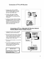
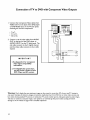
Connection of TV to DVD with Component
Video Outputs
I. Connect the ComponentVideo
cables from
VIDEO OUT on the back of the DVD player
to DVDVIDEO input on theTV back panel,
matching the correct components:
• YtoY,
• Cr to Cr,
• Cb to Cb,
2. Connect a set of audio cables from AUDIO
OUT on the back of the DVD player to
AUDIO, INPUT-3 on theTV back panel. The
red cable connects to the R (right) channel
and the white cable connects to the L (left)
channel.
IMPORTANT
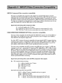
h SeeAppendix
4 for component
video signal compatibility
information.
2. For DigitalAudio connections,
see the Owner's Guides of your
DVD Player and AV receiver.
Warning:
Don't display the same stationary images on the screen for more than 15%of your total TV viewing in
one week. Examplesof stationary images are letterbox top/bottom bars from DVD disc or other video sources, side
bars when showing standard TV pictures on widescreen TV's,stock market reports, video game patterns, station Iogos,
web sites or stationary computer images. Such patterns can unevenly age the picture tubes causing permanent
damageto the T_. Pleasesee page 74 for a detailed explanation.
14
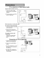
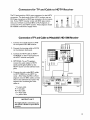
Connectors
for TV and Cable to HDTV
The TV back panel has 5 RCA type connectors, for the HDTV
connection. The back panel of your HDTV receiver may use
RCA type connectors or BNC type connectors for its connection. If your HDTV receiver comes with BNC type connections, you will have to purchase BNC to RCA adaptors, to
connect theTV to the HDTV receiver. These adaptors should
be available at electronics supply stores.
BNC to
RCA
Adaptor
Receiver
BNC
Adaptol
Fitted to
Connector
Connection
RCA
Connec_r
Connection of TV and Cable to Mitsubishrs HD-1080 Receiver
I. Connect the outside antenna toANT
on the optional HD-1080 receiver.
2. Connect the incoming cable toANT-A
on the television back panel.
3. Connect the HDTV cable to HDTV
CONTROL on the TV back panel and
the HDTV receiver back panel.
4. OPTIONAL: To useTV speakers,
connect the audio cables to HDTV
L(left) and R(right) AUDIO on the
HDTV receiver and the television back
panel.
5. Connect the color coded BNC cables
to HDTVVIDEO on the HDTV receiver. After fitting the BNC to RCA
adaptors onto the BNC cables, connect
them to the television back panel. The
sequence for connecting the color
cables is:
Y =
Pr =
Pb =
H =
V =
IIIIIIIIIIIIIIII
0111111011111111
IIIIIIIIIIIIIIII
IIIIIIIIIIIIIIII
green cable
red cable
blue cable
white cable
yellow cable
IMPORTANT
For Digital Audio connections, see
the Owner's Guides of your HDTV
receiver.
15
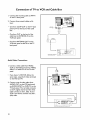
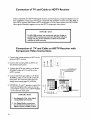
Connection
of TV and Cable to HDTV
Receiver
Industry Standards for HDTV RGB signals systems, synchronizations and signal strengths have not
been established. These inputs will not be compatible with all HDTV receivers that offer RGB. If
your HDTV receiver offers both a HDTV component (Y, Pr, Pb) video system and a HDTV RGB
video signals, Mitsubishi suggests you use the HDTV component video system.
IMPORTANT
If a HD-1080
receiver was connected and you change to
another DTV receiver, you must turn the Power off, then
unplug and plug in the television to allow the new HD
receiver to work correctly.
Connection
Component
of TV and Cable to HDTV
Video Connections
Receiver
with
I. Connect the outside antenna to ANT on the
optional HDTV receiver.
2. Connect the incoming cable to ANT-A on
the television back panel.
3. Connect the RCA type cables or the fitted
RCA/BNC cables toY, Pr and Pb on the
HDTV receiver.
4. Connect the RCA type cables or the fitted
RCA/BNC cables toY, Pr, and Pb on theTV
back panel. You must also select the DTV
Assign Input setting (page 35) of YPrPb.
5. OPTIONAL: To useTV speakers, connect the
L(left) and R(right) audio cables to the optional HDTV receiver and to HDTVAUDIO
on the television back panel.
IMPORTANT
I. SeeAppendix
compatibility
4 for video signal
information.
2. For Digital Audio connections,
see the Owner's
Guides of your
HDTV receiver
and AV receiver.
16
if.......
...........
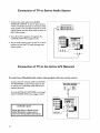
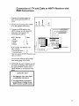
Connection of TV and Cable to HDTV
RGB Connections
I, Connect
the outside
antenna
to
HDTV
re-
ANT on the optional
ceiver.
2. Connect the incoming cable to ANTA on the television back panel.
ROA
A_p_r
a_C
Conn_tor
Receiver
with
_itt_d to
C0n_on
3. Connect the RGB cables to the
HDTV receiver and the televesion
back panel. The sequence for
connecting the cables is:
HDTV Receiver
Panel
G (green)
R (red)
B (blue)
TV Back
=
=
=
Y
Pr
Pb
If the receiver has separate sync*,
also
connect:
H (horizontal
sync) =
H
V (vertical sync)
=
V
do not connect
if HDTV Receiver
uses
"Sync on Green".
You must also select the DTVAssign
Input setting (page 35) of RGB.
4. OPTIONAL:To useTV speaker, connect
the L(left) and R(right) audio cables to
the optional HDTV receiver and to
HDTV AUDIO on the television back
panel.
IMPORTANT
I. SeeAppendix
compatibility
4 for video signal
information.
2. For DigitalAudio
see the Owner's
HDTV receiver
connections,
Guides of your
and AV receiver.
17
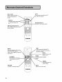
Select
Power
switch
Selects which A/V
will be controlled
remote
by the
/oT:ntShPeO
;rn?dcO.
for
, the
Numbers
Individually
or enter informasion
TV
SQV
into
QV
(SuperQuickView
lis
SUB
INPUT
Input-2,1nput-3
TM)
TM)
Scan through a memorized
favorite channels
(Ant-A,Ant-B,
(QuickView
Switchesto last channel viewed
HDTV
DTV, Input- I,
[DVD
receiver is connected,
subchannel number
component]
use to enter a
SLEEP
and Input-4)
Sets theTV
within
to turn off
2 hours
VIDEO
CHANNEL
View channels in increasing
y selects the Video
settings
or decreasing
order
AUDIO
- Individually selects the
Audio settings
VOLUME
Increases or decreases so
18
MUTE
Turns on or off the sound
Remote
Control
Functions,
continued
ADJUST
Selects menu items. Change
settings. Moves the PIP
on-screen location
ENTER
Use after selecting a
channel number or
menu item
GUIDE
When optional
HD-1080 HDTV
LIGHT
Press to light the white
buttons
receiver
is
connected,
control
CANCEL
MENU
Clear SQV and some_
menu
entries
use to
display the DTV
Channel Guide
on-screen
menu choices
PIP/POP
Use to display or
change PIP or POP
HOME
Exit on-screen
menus and
return to TV viewing
PIP INPUT
Use to select the
INFO
or POP input source
• Displays an on-screen
FORMAT
summary of currentTV
settings and V-Chip program
Change the size and
shape of the main TV
ratings
picture
PIP CH
EXCH
Change the PIP channel, for
Exchange PiP
Ant-A, Ant-B or DTV (with
and main TV picture
optional
© © © (i)
© © ©
©©O
©©©_
HD- 1080 receiver)
STOP
To stop aVCR, DVD or
REC
Manually record
programs on yourVCR
PAUSE
_Temporarily
REWIREV
stops a
VCR, DVD or CD or
freezes the PIPIPOP
Rewind and reverse search for the
VCR. Skip reverse for CD.
Reverse scan for DVD
FFIFWD
Fast forward
or forward
forward
PLAY
PlaysaVCR, DVD or CD
search for
for a CD. Fast
play for a DVD
19
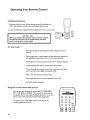
Operating
Installing
Your
Remote
Control
the batteries
I. Remove the back cover of the remote control by pushing the
tab in the direction of the arrow and sliding off the cover.
2. Load the batteries, making sure the polarities(+)
and (-) are correct.
IMPORTANT
When you replace the batteries in your remote control,
the remote may return to its initial setting. You may
need to set up your remote again.
@@
For best results
Be within
control
20 feet of the equipment
when using the remote
Don't press two or more buttons at the same time, unless you
are specifically instructed to do so in this owner's guide.
Don't allow the remote
Avoid dropping
control
the remote
to get wet or become
control
heated.
on a hard surface.
When cleaning the remote control, don't use any harsh chemicals. Use only a soft, slightly moistened
cloth.
Don't mix new batteries
with old ones.
Don't heat, take apart, or throw
Use AAA
Using the remote
control
alkaline
batteries
batteries.
with yourTV
You can use your remote to control the TV, CABLE/DBS/
DTV, VCR, DVD or AUDIO. The remote has been preset
to operate theTV and other Mitsubishi products. It can be
set to control other brands of audio/video equipment.
To operate the "IV, the select switch at the top of the
remote should be set toTV.
20
into a fire.
r_l
I-_
0000
000
O
O O
;;;oo
Remote
Control
of Other
Audio and Video
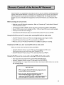
Programming
the Remote to Control
Audio and Video Products:
Other
Products
Brands of
Move the slide switch at the top of the remote to select the
audio or video product you want to control,
Press and hold the POWER button, so that it stays down when
you enter the code.
Enter the code for the equipment from the appropriate list,
exactly as stated. If there is more than one code number, try the
numbers, until you find the correct code.. After setting the code,
release the POWER button.
Point the remote at the equipment and press the POWER
button. If it is on and turns off or is off and turns on, the remote
will control the equipment. If not, try the next number.
VCR
Cable
Box
codes:
CABLE/DBS/DTVTTv]|
Cable box brand
General Instruments/
Jerrold
Oak
Pioneer
codeto enter:
111,119, 120, 121,122,
123, 124, 125, 126, 127
102, 137, 139
101, 116
Scientific Atlanta
111,112,113
Zenith
100, 117
To reset to default code. enter
Satellite
Satellite brand
Mitsubishi DTV - DBS
Dishnetwork
Huclhes*DSS
RCA*DSS
Sonv-DSS
Toshiba-DSS
Panasonic*DSS
Primestar
Receiver
000
If your
cable box
code is not
listed here,
please see
page 79
for a
complete
listinch
codes:
codeto enter:
173
175
173
176
177
170
174
178
|| _AUDtO
IMPORTANT
If you cannot turn the cable box ON
by pressing POWER, try pressing the
CHANNEL or the number buttons.
VCR
CABLE/DBS/DTV
TV
If your
satellite
code is not
listed here,
_lease see
page 79
for a
complete
listing.
To reset to default code, enter 000
VCR codes:
VCR brand
codetoenter:
Mitsubishi
Hitachi
JVC
001,002
020, 043,065
030,054, 059
043, 044, 051
041,042,043
020, 053,065
048, 049, 050
021,066
Philips/Magnavox
Panasonic
RCA
Sony
Toshiba
ro reset to default code, enter 000
If your
VCR
code is not
listed here,
please see
page 80
for a
complete
listing.
IMPORTANT
When set to TV, the PLAY, STOP,
REW/REV
and the FF/FWD
keys will
operate theVCR
after theVCR
codes
have been chosen.
21
Remote
Control
of Other
DVD
Audio
Product,
continued
Player codes:
DVD/LDP brand
codetoenter:
Mitsubishi (DVD)
Mitsubishi (LDP)
Panasonic
Pioneer DVD (LDP)
Sony
Toshiba
003
016, 017
250
252 (016, 017)
254
253
TO reset
code,
to default
AV Receiver
Audio brand
enter
000
with CD player
Kenwood
Onkyo
Pioneer
Sony
Yamaha
to default
If your
DVD code
is not
listed here,
please see
page 79
for a
complete
listing.
VCR
codes:
codeto enter:
If your
Audio
code is not
listed here,
please see
page 79
for a
complete
Mitsubishi AV receiver
To reset
and Video
010, 011
200, 208
209, 214
205, 207
222
201,202
code,
enter
O00
listing.
IMPORTANT
If the slide switch is set toTV when you enter an AV receiver code,VOLUME
and MUTE will control by theAV
receiver, rather than theTV. To return volume and mute
control to theTV, set the slide switch toTV, press and
hold POWER and enter 000.
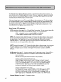
Additional
slide switch feature: -for multiple
AJV component
systems
After selecting the correct codes, you can use the slide switch to control more than one type of
A/V product. The possible equipment that can be set up for each switch position is shown in the
following table. Only one device is allowed for each slide switch position.
TV position:
• TV
• any A/V receiver
(volume, mute only)
Cable/DBS position:
• cablebox or
• satellite receiver
VCR position:
• anylisted VCR or
• Mitsubishi DVD or
player
Audio position:
• any listed AV receiver or
• Mitsubishi CD player or
• any listed cable box
DVD position:
• any listed DVD or
• any listed VCR or
• any listed cablebox
IMPORTANT
Some manufacturers may change their products, or they may use more than one remote
control system. If this is the case, your remote may not be able to operate yourVCR, DVD
Player, Cable Box, Satellite Receiver orAV Receiver.
22
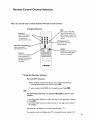
Remote
There
Control
Channel
Selection
are several ways to select channels with the remote
Changing
control:
Channels
SUB
When optional
Numbers*
i_eceiver
HD- 1080
is connected,
use
enter the number, the
after choosing
channelwill change _
in 4 seconds,or
after the third number
channel,to enter minor (sub)
channel
OQO
_QQ_
QV
(QuickView
a major DTV
TM)
press QVtosee the last
channelselected
SQV (SuperQuickView_
press to see stored
SQV channels,in order
GUIDE
,
Displays DTV Channel Guide
(when optional
Channel
press to view channe
order, including DTV
channels (when optional
HD-1080 receiver is
connected)
* Using the
ir
I
Number
For non-DTV
receiver
HD-I080
is connected)
buttons:
channels:
When changing channels directly, you can change them faster by:
I. entering three numbers; for channel 2, press 002
ENTER
2. press number and ENTER; for channel 2, press 2 then _.
OR
For DTV
nected:
channels when an optional
HD- 1080 receiver
is con-
I. Use the number buttons to select the one or two digit major channel.
SUB
2. Press _.
3. Use the number buttons to select the one or two digit minor channel
(if available).
Two asterisks will display if no minor channel exists:
17.**
Two question marks will display while TV is looking for minor channel: 12.??
23
Remote
Control
of the Sleep Timer
Setting
the SleepTimer
SLEEP
Press_
on the remote
J Sleep:
control.
TheTV
will display the message:
030 Min.
J
SLEEP
With each press of _
the time increases in 30 minute intervals
until the maximum of 120 minutes is displayed.
SLEEP
Release _
when the desired
time is set.
SLEEP
To see how much time is left until the timer goes off, press
once. The remaining time will display on-screen.
SLEEP
'
4
gg
_,rr
Canceling
......
the SleepTimer
SLEEP
Press_to
see the on-screen display.
SLEEP
Press _
until you see the message:
JSleep:
The timer will be canceled.
24
OFF
J
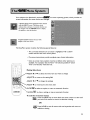
YourtelevisionhasMitsubishi's
exclusive
I_lllj_on
screen information
screenoperating
system, which provides on-
for menu choices and changes.
A picture (icon) will be highlightedwhen selected
with the ADJUST arrows. The picture (icon)
indicates that a submenu or automatic function can
be changed. Pressthe ENTER button to display
the options or start the function.
A square button indicatesthat you make
changesto this menu choice.
The ViewPoint system includes the following special features:
• The currently selected icon or button is highlighted with a yellow
outline and the text color will be yellow.
• On-screen instructions
provide complete menu choice information.
• Some on-screen menu options must be set before other options are
available. For example,"Set theTimer" will only be possible if"Clock
Time" and "Set Day" have been set.
Making Selections:
UST•
or •
to select the menu item you want to change
ADJUST _ to move to the setting field
ADJUST • or •
UST,
to change the settings
to move back to the menu item
ENTER_to
select an option, or start an automatic function
• °CANCEL.C_
Lto clear a setting, or stop an automatic function
To exit the on-screen menus:
MENU Press the MENU key to move back one menu screen at a time until
you exit all the menus to return to television viewing
OR
_
Press HOME to exit all menus with one keystroke and return to
television viewing
25
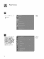
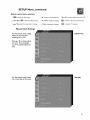
Menu
Screens
The Main Menu Screen will
always be the first screen that
appears when you press the
MAIN
Menu
MENU button.
Basicset up instructions and
procedures are available
through the SETUP menu
screens.
You can put channels
in memory,
set the time and
day, set your TV to be part of
a HomeTheater setup, view
the menus in English or
Spanish, and turn on or off
inputs connected to the
television.
26
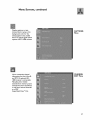
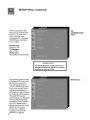
SETUP
Menu
Menu
Screens,
Display captions or text,
choose black or gray as the
background color for the
closed caption area, enable
the DTV channel guide (when
optional HDTV- 1080 receiver
Use to customize channel
information for Ant-A, Ant-B,
and DTV (if optional HD1080 receiver is connected).
Manually add or delete
channels from memory, name
channels for Ant-A and Ant-B,
or add your favorite channels
to a SQV
(SuperQuickView TM) list.
continued
CAPTIONS
Menu
CHANNEL
EDIT Menu
27
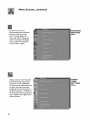
Menu
28
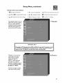
Screens,
continued
Set yourTV to turn on
automatically, block unwanted
programs with the V-Chip
lock, converge (align) the
three main colors, change the
screen resolution and display
a blue screen when showing
an input with no signal.
ADVANCED
FEATURES
Menu
Adjusts some or all of the audio
and video settings. Each input
can be set to your preferences.
AV Reset on the menu allows you
to return the audio and video
settings for the current input, to
the factory presets. AV Reset on
the front panel resets all inputs at
once. Enhance the brighter parts
of dark pictures.
AUDIO/
VIDEO
SETTINGS
Menu
Remote control menu selection:
MENU
1. _
to display
the Main Menu
4. •
to move to the setting field
5. •
or •
ENTER
2. •
or rand
_
to select the SETUP menu
to change
the setting
7.•
or •
MENU
to select
another
to return
to the previous
to return
to TV viewing.
menu
item
menu
OR
HOME
3. •or
Vto
select the menu item to change
6. • after making your changes
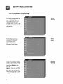
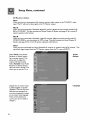
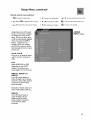
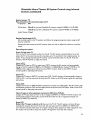
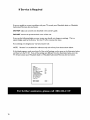
MEMORIZE
CHANNELS
This selection memorizes the
channels yourTV can receive
and skips the unused or weak
channels.
INPUT
CHANNELSTHAT CAN BE MEMORIZED
ANTENNAA AIR
2thrOugh 69
ANTENNAB AIR
2thm_Jh
ANTENNAA CABLE
I through _25
ANTENNA B CABLE
1 Lhrou_h 125
HD_1080 DTV
1 through
69
g9
IMPORTANT
DTV
Note
If you have connected a Mitsubishi HD-1080 receiver, you may use this
Memorize
Channels menu to memorize
digital channels. For any other
HDTV
receiver, you will need to use the channel memorization
system in
that receiver's
menu system.
You can stop the memorization at any time by pressing
MEMORIZE
Menu
CANCEL
Channels memorized before
canceling will stay in memory.
After channels are
memorized, your remote
control will:
PIP will not
display in
the DTV
mode
Select memorized channels in
ascending or descending
order by pressing the channel
button.
29
OR
SETUP
AUTO
Menu, continued
(automatic)
Clock
Settings
The clock setting of Auto will
automatically set the day and
time using Extended Data
Service (XDS) time data
available when tuned to a PBS
or other channel that carries
this service,
Clock
Setting
For the Auto mode you
will need to select the
correct time zone
Time
Zone
(Atlantic, Eastern, Central,
Mountain, Pacific,Alaska
In the auto mode you need
to select the Daylight Savings
Time (DST) option that your
state uses (Applies: uses
DST or
Ignores: does not use DST).
The clock time and the day
will be automatically set, after
tuning to a PBS or other
30
Daylight
Savings
SETUP
Menu, continued
Remote control menu selection:
MENU
1. _todisplaythe
Main Menu
4. •
to move to the setting field
5. •
or •
ENTER
2. •
or Vend
_
to select the SETUP menu
to change
the setting
7.•
or •
MENU
to select another
menu item OR
to return to the previous
menu OR
HOME
3. •or
Vto
select the menu item to change
Manual
Clock
6. •
after making your changes
to return
to TV
viewing,
Settings
For the Manual clock setting,
select the current time,
including AM or PM.
ClockTime
Press • or • to slowly adjust
the time. Press and hold
• or • to quickly adjust the
time,
For the manual mode, select
the current day of the week.
Set Day
31
SETUP
Menu, continued
The AV Connection Menu
allows you to customize the
way your TV works with
other audio and video
components, for a complete
Home Theater experience.
You can adjust:
AV
CONNECTION
Menu
AV Network
(Active or Off)
TV Speakers
(On or Off),
AV Receiver
(None, Mits A, Mits B, Other)
Set theAV Network to Off, if you are not
using the AV Network System, for channel
I
IMPORTANT
11
selection to work correctly.
Set to Active if you are using
a MitsubishiVCR with Active
AV Network connections.
This will simplify several
common TV/VCR operations
to just a few presses of the
remote control buttons. If
AV Network is set to Off, the
AV Network will still transfer
Mitsubishi VCR remote
control signals to a Mitsubishi
VCR that has AV Network
connections. This is useful if
theVCR is placed inside a
cabinet that blocks the direct
signal from the remote
control. For a detailed
explanation of Active AV
Network, see page 65.
32
AV Network
Setup
Menu,
continued
Remote control menu selection:
MENU
1. _
to display the Main Menu
4. I_ to move to the setting field
ENTER
2. •
or rand
_
to select the SETUP
menu
5. •
or •
to change
the setting
7.•
or •
MENU
to select another
to return
to the previous
to return
to TV viewing.
menu item OR
menu
OR
HOME
3. •or
Vto
select the menu item to change
6. • after making your changes
This selection will turn on or
off the TV's internal speakers.
You may select Off when
sending the sound through a
separate stereo system or
surround sound AV receiver.
TV Speakers
IMPORTANT
Changing theTV Speakers from OFF to ON will cause theTV speakers to turn
on. To prevent damaging theTV speakers from a sudden increase in volume,
make sure theTV volume is turned down before choosing ON.
Whether or not you have
connected the monitor
AV Receiver
video output of an AV
receiver to the TV's
INPUT- I video input, you
will need to set the AV
Receiver correctly to one of
the following: Mits-A, MitsB, Other or None.
See the next page to determine your correct choice.
33
Setup
AV Receiver
Menu,
continued
choices:
None
When you have not connected an AV receiver monitor video output to theTV INPUT-I video
input, The TV will send a video signal to the TV Monitor output,
Mits-A
When you have connected a Mitsubishi digital AV receiver (digital surround sound) model M-VR
800 or M-VRI000. This also activates the HomeTheater IR system (see page 67 for correct IR
system operation information).
Mits-B
When you have connected a Mitsubishi digital AV receiver (digital surround sound) model MVR700, M-VR900 or one introduced in 1999 or later. This also activates the HomeTheater IR
System (see page 67 for correct IR system operation information).
Other
When you have connected any other MitsubishiAV receiver or another brand of AV receiver. This
also blocks signal output from the TV Monitor output when the TV is set to INPUT- I.
Select Fixed if your Audio
Receiver or Stereo System
has a remote control. This
Audio
Output
allows you to adjust the
volume with that remote.
Select Variable if your Audio
Receiver or Stereo System
does not have a remote. This
allows you to use theTV to
Display the on-screen menus
in either English or Spanish
(Espa_ol). The first time your
television was powered on,
you were requested to select
an on-screen menu language.
If the current selection is
correct,
you
change it.
34
do
not
need
to
L_gu_e
Setup
Menu,
continued
Remote control menu selection:
MENU
1. _
to display
the Main Menu
4. •
to move to the setting field
5. •
or •
ENTER
2. •
or rand
_
to select the SETUP menu
to change
the setting
7.•
or •
MENU
to select
another
to return
to the previous
to return
to TV viewing.
menu
item
menu
OR
OR
HOME
3. •or
Vto
select the menu item to change
Assign Input turns off unused
inputs, or turns them on again,
or changes the name of the
input. If you turn off an input,
it will be automatically skipped
when you press the INPUT
button. If you have connected a DVD with component YCrCb output, it will be
automatically turned on. Input
choices are:
Ant-A,
Ant-B
turns
or off antenna
inputs
connect
antennas
or
on
used to
cable.
6. • after making your changes
ASSIGN
INPUT menu
DTV
select RGB,YPrPb or OFF,
depending on the HDTV
receiver
connections
you
made (pages 14 and 15), if any.
INPUT-I,
INPUT-2 or
INPUT-3
turns off unused inputs or
cycles through a list of preset
names for audio video product
connected to the TV back
panel terminals.
Examples of preset names are:
VCR I ,VCR2, DVD, CAM, etc...
INPUT-4
turns off unused input or
cycles through a list of
preset names for audio
video product connected
to theTV front panel
terminals.
35
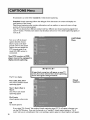
Broadcasters can send either standard
or text closed captioning,
Standard closed captioning follows the dialogue of the characters
small section of the screen.
Text closed captioning often contains information such as weather
portion of the on-screen program.
Your TV can decode four different standard and four different text
each TV station. However, each station may broadcast only one or
none at all.
on-screen and displays in a
or news and covers a large
closed captioning signals from
two closed captioning signals, or
CAPTIONS
Menu
Turn on or off the closed
caption decoder, choose
black or gray as the background color for the closed
caption area and enable the
DTV channel guide (if optional HD-1080 receiver is
connected).
Your DTV receiver or DVD
player may not be equipped
display closed captioning.
to
IMPORTANT
A large black or gray box will appear on yourTV
screen, if you have selected text closed captioning,
and no text signal is being broadcast.
The TV can display:
CC I, CC2, CC3, CC4
one of four standard closed
captioning signals
Closed
Captions
Text I ,Text 2,Text 3,
Text 4
one of four text closed
captioning signals
On if mute
closed captions when mute
Off
no closed captions
If you select"On if mute" the standard closed captioning signal (CC I) will appear whenever you
use the MUTE button. If you set the decoder to a"standard" closed caption setting or"On if
mute" and tune to a broadcaster that is not sending a caption signal, no closed captions will appear.
36
Captions
Menu, continued
Remote control menu selection:
MENU
1. _todiaplaytha
Main Menu
4. _
to move to the setting field
5. •
or •
ENTER
2.
•
or rand
_
to select CAPTIONS
menu
to change
the setting
7.•
or •
MENU
to select
another
to return
to the prewous
to return
to TV
menu
item OR
menu
OR
HOME
3. •or
Vto
select the menu item to change
6. • after making your changes
CC
Background
To make the closed captions
easier
to
read,
you
viewing,
can choose
to display the background
color as either black or gray
translucence.
IMPORTANT
The content of captions are determined
by the
broadcaster.
If your captions show strange
characters, misspellings,
or odd grammar, it is
not a malfunction
of theTV.
If connecting an optional
HD-1080 receiver, the DTV
Channel Guide can display
channel details for the currently selected station.
DTV Channel
Guide
DTV channels have both major
and minor channels capability.
A major channel may have
several minor channels. Minor
channels 01-99 are for broadcast viewing. Channel information and guide availability is
determined by the broadcast
stations.
Some HDTV broadcasts will
only contain major channels
and may not contain channel
information.
37
SelectAnt-A, Ant-B or DTV
(with optional HDTV receiver). For each antenna,
you can add or delete channels in memory, name channels and add channels to the
SQV (SuperQuickView
TM)
Antenna
list.
IMPORTANT
DTV
Note
The DTV antenna will appear
as a selection on the Channel
Edit menu when the
Mitsubishi HD-1080
H DTV
receiver
is connected.
If
another HDTV
receiver is
connected, DTV will not
appear as a selection.
Select the channel you want
to add or delete from
memory, name, or add to the
SQV list.
38
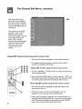
Channel
The Channel
Edit Menu, continued
Remote control menu selection:
MENU
1. _
to display the Main Menu
4. •
to move to the setting field
7.A or •
to select another menu item OR
ENTER
2.
Aorrand
_
tose]ect
CHANNEL
EDFmenu
5. A or r to change
the setting
_u
to return to the previous
menu
OR
HOME
3. Aor
•to
select the menu item to change
6. •
after making your changes
After all available channels
have been memorized with
the "Memorize Channels"
feature, weaker channels
viewed with Ant-A or Ant-B
can be added back in or
unwanted channels can be
deleted, on an individual basis.
_
to return to TV viewing,
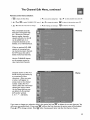
Memory
When an optional HD-1080
receiver is connected, you
can memorize major channels
for DTV input, then add or
delete memorized channels.
Use the CHANNEL button
on the remote control to
view memorized channels.
Channels shown on Ant-A or
Ant-B can be given names, up
to a maximum of four
characters. After you enter
a name, it will appear on
screen, next to the channel
number. Select Ant-A or
Ant-B. Select the memorized
Name
channel you want to name.
At the Name field, you can
use letters (A-Z), numbers
(0-9) and/or symbols
(t . &' / : * - and blank).
CANCEL
If you want to change your selection while in the option field, use _
to delete the current character. You
will move one position back. If you press CANCEL
_
while at the first character, the entire name will be deleted.
Press • or • to change a letter. Press _
after choosing each letter and after the Name is chosen.
39
The Channel
Edit Menu, continued
SQV
SQV (SuperQuickView
allows you to put together a
list of your favorite channels,
from Ant-A, Ant-B or DTV (if
optional HD-1080 receiver is
connected).
TM)
You can store up to 6 SQV
channels in each of the 9
different memory banks.
Once you've added a channel
to the SQV memory, the
letters "SQV" and the
memory bank number appear
under the channel number,
even if you tune to the
channel using another
method.
Changing SQV channels and banks using only the remote
control
I. Press the SQV button repeatedly to see the desired channel.
2. To change memory banks, press a number button within 5
seconds of pressing the SQV button.
@@
@@
@@
@@
Adding
SQV channels using only the remote
control
I. Use the CHANNEL or number buttons to select the channel you
want to add to the list.
2. Press and hold the SQV button for about 3 seconds. "SQV" and
the memory bank number will appear under the channel number,
to show that the channel has been added to SQV memory.
Removing
SQV channels using only the remote
control
I. Press the SQV button repeatedly to select the channel to be
removed from the list.
2. While the channel number and SQV indicators are still
displayed on the screen, press the CANCEL button.
3. When the SQV indicator disappears, the channel has been canceled from the SuperQuickView list. If you wait until the channel
and SQV indicators disappear automatically, then the CANCEL
button will not remove the channel from the list.
40
Remote control menu selection:
MENU
1. _
to display
the Main Menu
4. •
to move to the setting
5. •
or •
field
ENTER
2. •orVand
FEATURES
_
to select ADVANCED
menu
to change
the setting
7.•
or •
MENU
to select
another
to return
to the
to return
to TV viewing.
menu
previous
item
menu
HOME
3. •or
Vto
select the menu item to change
6. • after making
your changes
TIMER
The timer will automatically,
at a specific time, turn the TV
on, if it is off. It will tune to a
channel on:
Ant-A_
Ant-B,
DTV (if optional HD- 1080
receiver is connected)
or select:
INPUT- I, 2, 3 (DVD
component) or 4.
IMPORTANT
TheTV's
clock must be set before you can set
the timer. If you haven't set the clock and/or
day, you will see the CLOCK
Menu instead of
the Timer menu.
The timer can be turned On
or Off. If you turn On the
Timer, you need to select the
time to turn on, the day to
turn on, the input and the
channel to display. Later, if
the timer turns theTV on,
the message "Press a key for
theTV to stay on", is shown.
If you don't press a button on
the remote control or front
panel within 5 minutes, the
TV will automatically turn off.
Timer
41
OR
OR
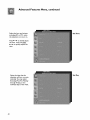
Advanced
Select the hour and minute,
Features
Menu, continued
SetTime
includingAM or PM, when
the television is to turn on,
Press • or • to slowly adjust
the time, Press and hold
• or • to quickly adjust the
time,
Select the days that the
television will turn on automatically, You may select
Everyday, Mon-Fri (Monday
through Friday), or the
individual days of the week.
42
Set Day
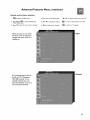
Advanced
Remote control
Features
menu selection:
MENU
1. _to
display
Menu, continued
the Main Menu
4. •
to move to the setting
5. •
or •
field
MENU
ENTER
2.
• or rand
FEATURES
3. •or
Vto
_
to select ADVANCED
menu
select the menu item to change
Select the input to use when
the timer turns on the TV, or
7.•
to change
the setting
HOME
6. • after making
your changes
or •
to select another
menu item OR
to return to the previous
menu OR
to return to TV viewing.
Input
changes the input, if the TV is
already on.
Channel
If the selected input is Ant-A,
Ant-B or DTV (if optional
HD-1080 receiver is connected) channels, you can
have the television turn on to
any memorized channel.
43
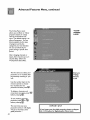
Advanced
Features
Menu, continued
V-CHIP
PARENT
LOCK
The V-Chip Parent Lock
allows you to Block or Allow
programs based on ratings
sent by the broadcast stations. The default setting is to
allow all programs. You can
block programs by the type
of program and by the
categories you want blocked.
Or you can block all programs during a specific time
period.
After changing channels or
inputs,there may be up to a 5
second delay, before the
V-Chip block takes effect.
The first time you select your
passcode, or to re-select after
permanently canceling it, you
will:
Entry to
V-Chip
Parent
Lock
Use the number keys on the
remote
control
to
choose
four numbers for the
ENTER
passcode and then press_.
To delete a character and
CANCEL
move back one space, press
ENTER
before pressing_.
To exitwithout
enterin_ a
MENU
ROME
before pressing_.
The next time you see a
passcode screen, it will display
"To go to the menu, enter
your passcode_."
44
I
IMPORTANT
If you forget your four-digit passcode, please see Appendix 3 : Procedure for Bypassing the Parent Lock.
Advanced
Features
Menu, continued
V-Chip rating information is
not currently included in all
programs sent by broadcasters. This means you may not
be able to block the programs. For a more complete
blocking system, see the
V-CHIP HOURS/LOCK BY
TIME section.
V-Chip rating information that may be included with the programs includes:
I. TV Ratings
- Are age-appropriate
as determined
by broadcasters.
2. Lettered categories - May or may not be sent as part of the V-Chip information provided by
broadcasters, along with TV Ratings. Not every lettered category will apply to everyTV Rating.
3. Programs Not Rated - Some programs may carryV-Chip information of"Not rated","N/A"
or "None". These programs may include news, sports, weather, emergency broadcast bulletins or
foreign programming.
4. Movie Ratings - For movies previously shown in theaters or Direct-to-Video
ratings are independent of anyTV or Lettered category rating.
Some programs
include:
may not carryV-Chip
information
and cannot
movies. Movie
be blocked.
These may
I. Older programs, whether on television, or videotape, disc, etc_.
2. HD and 480p programs.
TV
Ratings
for television
OFF
TV-Y
TV-Y7
TV-G
TV-PG
TV-14
TV-MA
programs
including
made-for-television
movies:
(youth)
(youth, 7 years and up)
(general audiences of all ages)
(parental guidance suggested)
(I 4 years and up)
(mature audience)
Example: If you selectTV-PG as theTV Rating then, TV-Y,TV-Y7,TV-G andTV-PG will be allowed.
45
The V-Chip
Lettered
Parent
Categories
withTV
Lock, continued
to be used
Age
Categories
Ratings:
TV-Y
TV-Y7
TV-G
TV-P
TV-14
TV-MA
FV - FantasyViolence
D - Sexual Dialog
L - Adult Language
S - Sexual Situations
V -Violence
Example: If you blockTV-MAV
Programs
Not
then, TV-PGV
Lettered categories that may
be available for blocking
FV
D,L,S,V
AL, S,V
L,S,V
andTV-14 V will also be blocked.
Rated:
This is an actual broadcast rating for programs that contain V-Chip information
"N/A" or "None".
of "Not Rated",
Example: News, sports, weather, foreign programs and emergency broadcast bulletins.
IMPORTANT
When Programs Not Rated is set to block, emergency
may be blocked along with other Not Rated programs.
when selecting this setting.
For Movies
previously
Off
G
PG
PG-13
R
NC-17
X
shown
in theaters
programs
Use care
or Direct-to-Video:
(general audience)
(parental guidance suggested)
(I 3 years and up)
(restricted)
(18 years and up)
(adult)
Example: If you select PG- 13 as the Movie Rating then, G, PG and PG - 13 will be allowed.
This example shows the
settings when the
Movie Rating is PG-I 3,
TV Rating is TV-PG and
Lettered Categories D and S
are blocked.
46
V-Chip
Example
The
V-Chip
Parent
Lock, continued
Remote control menu selection:
MENU
1. _todisplaythe
Main Menu
4. •
to move to the setting field
7.•
5. •
or •
_u
or •
to select another menu item OR
ENTER
2, •
or •
and _
to select the menu category
to change
the setting
to return to the previous
menu OR
HOME
3. •or
Vto select the menu item to change
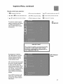
Using theV-CHIP HOURS/
LOCK BY TIME menu, you
can activate theV-Chip or
lock the entire television,
during specific hours by:
6. • after making your changes
to return to TV viewing.
V-CHIP
HOURS/
LOCK BY
TIME
I. Blocking some programs
during specific hours, using
V-Chip Start and StopTime.
or
2. Blocking all programs
during specific hours by
selecting the Lock byTime
feature with LockTime and
UnlockTime.
Use theV-CHIP
HOURS
Start and StopTimes to block
programs during specific
hours, and later have V-Chip
blocking turn off automatically. If theV-Chip start and
stop time are the same, the
V-Chip will be on 24 hours a
V-Chip
Start
Time
V-Chip
Stop
Time
day.
Press •or•
to slowly adjust
the time. Press and hold
• or • to quickly adjust the
time.
47
The
V-Chip
Parent
Lock, continued
Lock by Time is an entire TV
locking system based on
viewing times. When used,
the entireTV will be locked
Lock byTime
LockTime
UnlockTime
between the specified hours.
To use theTV during the
locked period, you must enter
your four digit passcode.
Passcode
Screen
To view a bJocked program
after using theV-Chip block,
you will have to enter your
passcode to temporarily turn
off the block_
If LockTime
and UnlockTime
are set to the same time,
the Parent Lock will be on 24 hours a day.
48
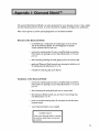
Advanced
Your Mitsubishi Projection TV
has three picture tubes with
large diameter lenses which
are aligned to properly
converge the projected light
beams on the screen. Each
picture tube projects only
one color: red, green or blue.
During production, your
television was carefully
adjusted to properly align
these colors.
Features
Menu, continued
CONVERGENCE
As a special feature, you have
the ability to adjust the color
convergence, should you
think that the red and/or blue
light beams are out of
alignment.The green beam
acts as a fixed reference for
aligning the red and blue
beams.
Convergence aligns the
whole screen at one time.
Advanced Convergence aligns
64 individual adjustment
positions.
CONVERGENCE
Menu
Select either Red Convergence or Blue Convergence
to begin alignment.
49
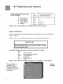
The Advanced
Features
Menu, continued
When the Red and Blue lines
are properly converged, the
on-screen crosshairs will be
white. You can useA, ,, Vor •
to move the colors toward
or away from the crosshairs,
until the crosshairs are white.
Red
Convergence
Press _
to switch between
RED and BLUE. For
Advanced Convergence, press
AUDIO
. Read the on-screen
display for further instructions.
To restore the convergence
factory settings, select Reset
Factory Default from the
CONVERGENCE
menu.
The message "Convergence
completed" will display when
the factory defaults are
restored.
50
Reset
Factory
Defaults
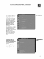
The Advanced
Features
Menu, continued
Before you can adjust the
Advanced Convergence,
you must adjust the
convergence for both Red
and Blue.
Use theA, I_ rot
Advanced
Conve_
• buttons
to move the flashing bracket
to a position that needs
adjustment.
gence
ENTER
Press _
to stop the
flashing. Use theA, I_, • or •
buttons to move the red or
blue line.
A position is converged when
all three lines combine to
make a white line.
ENTER
Press_
when aligned, the
bracket will start flashing.
UseA, ,, • or • to move to
a new position.
When finished converging
press the_
button to save
your changes,
Use then
button to
switch adjusting between the
Red and Blue lines.
liMPORTANT
There are more than 64 line
intersections.
However, the
bracket will only stop on the 64
adjustment
positions.
51
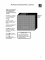
The Advanced
Your Mitsubishi television
_utomatically doubles the
lines of the standard 480i
Features
Menu, continued
Video
Display
(interlaced) pictures. This
provides a smoother, more
film like image.
The default doubling is 480p
(progressive). If you prefer,
you can choose to display the
picture as 960i (interlaced).
Video Mute lets you display a
blue or gray screen when no
signal is being received, for
INPUT-I,2, 3 or 4.
The V-Chip block will remain
off for that channel or input,
until the TV power is turned
off and turned on again
52
Video
Mute
Eachof the 7 inputshasits
ownaudiovideomemory.
Youcanadjustthe individual
audioor videosettingsfor
eachinput.Therearetwo
waysto adjustthesettings:by
usingthe remotecontrol
buttonswiththe Menu
screen,
or withtheAUDIO
orVIDEObuttononthe
remote
AUDIO/
VIDEO
SETTINGS
Menu
control.
After adjusting, every time
you select that input, the new
settings will be used.
Select the input for the audio
and/or video memory
settings you want to change.
AV
Memory
53
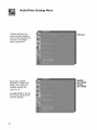
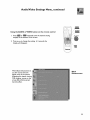
Audio/Video
AV Reset will return the
audio and video settings of
the currently selected input's
memory to the original
factory adjustments
Select either AUDIO
SETTINGS orVIDEO SETTINGS, Then adjust the
individual settings with
See pages 56-58 for descriptions of the individual audio
and video settings.
54
Settings
Menu
AV Reset
AUDIO
SETTINGS
VIDEO
SETTINGS
Audio/Video
Settings
Menu,
continued
VIDEO
f
Using the AUDIO
I.
orVIDEO
button
on the remote
Press_AUDIO or _
repeatedly until the desired setting
displays at the bottom of the screen.
AUDIO
control
ADJUST
2. Press 1orl_to change the setting. In 5 seconds the
display will disappear.
MENU
When Black Enhancement is
on, dark scenes have the
lighter parts of the picture
brightened for better viewing.
With brighter scenes on the
screen, Black Enhancement
has little effect.
Black
Enhancement
55
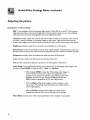
Audio/Video
Adjusting
Descriptions
Settings
Menu,
continued
the picture
of video settings
IRIS is the Intelligent Room Illumination (light) Sensor. When IRIS is on, your TV will automatically adjust the picture contrast and brightness for the best picture based on your room lighting.
When turned on, Contrast and Brightness cannot be adjusted manually.
TM
Contrast provides a slider that controls the level of white-to-black in the picture. Low contrast
will show a variety of shades in the darker images on the screen. High contrast will show the
screen's dark images more uniformly black and make the colors on the screen seem more vibrant.
Brightness
provides a slider that controls the overall brightness of the picture.
Auto Picture for Ant-A and Ant-B, senses the tuner signal strength. It adjusts picture color and
sharpness for the best picture.When turned on, sharpness and color cannot be adjusted manually.
Sharpness provides a slider that adjusts the detail and clarity of the picture.
Color provides a slider that determines the intensity of the color.
Tint provides a slider that adjusts the proportion
of red to green in the picture.
ColorTemp
(Color temperature) allows you to set how theTV will display white images. Your
choices are"Low 6500K or Low (for HD)", "High" or"Medium"
With the Low 6500K or Low (for HD) setting, white images onscreen will have a warm cast to them. This adjustment is an
average and can vary due to ambient room lighting, video scene
brightness and the TV's age. The Low 6500K represents the
6500°K industry standard for NTSC (non-HD) pictures.
• With the High setting, white images on-screen will have a cool
cast to them. This setting may provide the most realistic picture
under bright lighting.
• With the Medium setting, white images on-screen will be
balanced between the Low (warm) and High (cool) settings.
Video
56
Noise reduces minor video noise (graininess) in the broadcast or input signal.
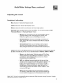
Audio/Video
Adjusting
Descriptions
Settings
Menu,
continued
the sound
of audio settings
Bass enhances or reduces low frequency sound,
Treble enhances or reduces high frequency sound
Balance adjusts the level of sound between the left and right speakers.
Surround creates simulated stereo and surround effects. You can set this setting to "Off",
"Simulated
Stereo" or "Surround
Sound". Select:
Off when you do not want to use any surround effects. Set the
surround setting to "Off" when using an A/V receiver with
Dolby _ Pro Logic Surround, or Dolby Digital Surround.
Simulated Stereo when you are watching a non-stereo program. Your TV will create a simulated stereo effect by using the
TV's speakers.
Surround Sound when you are watching a stereo program.
Your TV's internal speakers will create a simulated surround
effect, making the sound seem to extend around and behind you.
Listen to for Ant-A or Ant-B determines how your TV will receive a broadcast audio signal and
play back the sound that you hear. You can set this function to "Stereo","SAP"
or "Mono"
Stereo is the default setting. With this setting, theTV will play
stereo broadcasts in stereo an._dd
mono broadcasts in mono. The
word "Stereo" will be displayed when you tune to a channel
broadcasting stereo programming.
SAP is an additional monaural soundtrack that you can't hear
during normal TV viewing. The SAP signal might be related to the
program you are watching, such as a soundtrack in a foreign
language,or it might be unrelated such as a weather report. If
the SAP signal is broadcast, the letters "SAP" will appear onscreen when you tune to that channel. Choose "Listen to: SAP"
to hear the SAP signal.
Mono will reduce background noise and should be used if you
are receiving a weak stereo audio signal. The sound will be only
in mono even if the program you are watching has stereo audio.
"Dolby""AC-3;'"Pro Logic" and the double-D symbol are trademarks of Dolby Laboratories Licensing Corporation.
1992 Dolby Laboratories, Inc. All rights reserved.
Copyright
57
Audio/Video
Adjusting
Settings
Menu,
continued
the sound, continued
Listen to for DTV (when using optional HD-1080 receiver) allows you to determine which
language your TV will receive a broadcast in, if that language is available for the program. The
possible choices are:
•
•
•
•
English
French
Spanish
Portuguese
• German
• Italian
• Other
Listen to is not available for INPUTs
PIP Audio Output
is available on models WT-46805,WS-55805,WS-55905,WS-65905
and WS73905. Stereo, SAP,Mono or DTV languages,as available, can be heard through an amplifier or
wireless headphones connected to the PIPAUDIO outputs (on the back of the television). This
feature allows you to hear sound that is being broadcast through the displayed PIP. Once connected, if the PIP is not displayed you will be able to hear the main TV program through the headphones.
If the PIP input's Audio Output cannot be adjusted, then the letters "N/A"
when this feature is chosen.
will appear on-screen,
Level Sound automatically equalizes the volume level of programs that contain significant sound
level differences from one segment to another, for example: regular programming to commercials.
To receive the best audio fidelity for music programs, you may want to turn this setting to Off.
58
When your remote control has been programmed to operate other manufacturer's products the
functions it performs on each layer will vary by manufacturer and model. The most common
functions are:
YCl_
• POWER
• CHANNEL
• REC
• STOP
• PAUSE
up/down
• REW/REV
• PLAY
• FF/FWD
Mitsubishi VCRs will be compatible with additional buttons
Cable Boxes and Satellite
•
•
•
•
Receivers:
POWER
CHANNEL up/down
ENTER (on some models)
ADJUST up/down/left/right
(on some models)
AV Receivers:
• POWER
• VOLUME
• MUTE
• 0-9 number buttons (on some models)
• CANCEL (on some models)
• GUIDE
(on some models)
Mitsubishi
AV Receivers
• Direct Input Selection buttons
(several specific buttons,
on some models)
Mitsubishi CD Players when used in combination with
Mitsubishi AV Receivers (use audio code 010 or 01 I ):
• PLAY
• PAUSE
• FF
• STOP
• REW
DVD and Laser Disc players
(not all functions for all models):
• POWER
• 0-9 number buttons
• MENU
• CANCEL
• STOP
• PAUSE
• REW
• pLAy
• ARROW
• ENTER
up/down/left/right
59
PIP (Picture
in Picture),
Side-by-side
and POP (Picture
outside Picture)
Mode
You can display a large or small PIP (Picture-in-Picture).
For widescreen modelsWT-46805,
WS-55805, WS-55905,WS-65905 and WS-73905 you can also display a side-by-side picture, or
three or nine POP's (Picture-outside-Picture).
PIP/POP
Activating
PIP/POP
For models VS-50805 and VS-60805, press PIP/POP once to turn on PIR a second time for a smaller
size PIP and a third time to turn off PIR
For widescreen models,WT-46805,WS-55805,WS-55905,WS-65905
and WS-73905, press PIP/POP
to activate the PIP and POP modes. Each additional press within three seconds will change the PIP
to the next mode. Press PIP/POP to see a side-by-side image, again for three POP's, again to see
nine POP's, again to see a large PIP and again to see a small PIR To turn off the PIP or POP, wait
more than ten seconds and press PIP/POR
The next time
shown.
PIP INPUT
the PIP/POP
is used, the last selected
PIP or POP will be the first
PiP INPUT
To see a picture
in the PIP inset, you may need to select
an input source.
If the only input you have
connected is ANT A, then both the main picture and the PIP or POP will both be from ANT A.
If you have connected other video equipment, you may be able to view pictures coming from these
products in the PIP/POP inset or as the main picture.
Below is a list of main picture and PIP or POP sources that cannot be used together:
•
WhenAnt-A
is the main picture,Ant-B
cannot be the PIP/POP
source.
•
When DTV 480p, HD, or DVD 480p is the main
POP is not available
from
DTV is the main picture, component
INPUT-3 cannot be the PIP/POP source.
•
When
•
When
Component
picture,
PIP/
any input or antenna.
video from
INPUT-3
video from
is the main picture,
DTV cannot be the PiP/POP source.
• For widescreen models in the side-by-side
mode, the same
picture cannot be shown in the main picture and side-by-side.
To see if DTV 480p, HD or DVD 480p is the main picture, press the INFO button. The on-screen
display will list 480P or HD 16:9 when those signals are received.
60
Using PIP and POP Features,
continued
PIP INPUT
Using the PIP INPUT
button
PIP/POP
A_t_ 002 KCE_
Stand_
TV-_G DLSV
SQV4
I. To view a PIP image, press _.
plPA017
PIP INPUT
z
To see the available PIP inputs, press_
repeatedly. The input
name will be displayed on screen for about five seconds. The
equipment connected to INPUT- I, 2, 3 (DVD component), 4 or
DTV needs to be turned on to show a PIP or POP
PIP CH
Using
the
PIP
CH
button
8
When a PIP or POP channel is displayed, the PIP CH button
can change PIP or POP channels for Ant-A,Ant-B or DTV
(when optional HD-1080 receiver is connected).
PIP/POP
I. Press _.
PIP CH
2. Press
to show a different channel on the PIP or POP
ADJUST
Using the ADJUST
button
I
) with PIP or POP
PIP:
ADJUST
Press {
to move the PIP image anywhere on the screen.
POP:
ADJUST
Press
......
to change to a different"live"
POP image.
VCR
PAUSE
Using the PAUSE buttonO with PIR Side-by-Side or
POP (select switch must be inTV position)
PIP:
PAUSE
While viewing a PIP or side-by-side channel, press O to freeze
the image.
Press
P_SE again to return to a live picture.
PAUSE
To bring a frozen PIP image on-screen,
press _.
POP:
PAUSE
Press _ to keep the same active POP and stop automatic switching.
PAUSE
Press _ again to return to automatic POP switching.
61
Using PIP and POP Features,
Using the EXCH
_i _'° [_'_°_°
button
continued
with PIP
PressEXCH
_ to exchange the PIP and main picture image.
Using the PIP/POP button to display Side-by-Side
(Picture-Outside-Picture's)
for models
WT-46805,WS-55805,WS-55905,WS-65905,WS-73905
or POP'S
Your choices are to view:
Side-by-Side
Three POP's
Nine POP's
PIP,large or small
POP 1
MAIN
PICTURE
MAIN
PICTURE
Side-by-Side
POP 2
MAIN
PICTURE
POP 1
POP 2
POP 3
POP 4
POP 5
POP 6
POP 7
POP 8
POP 9
POP 3
PIP/POP
To display the PIP or POP you want, pressQ
POP sequence is displayed.
until the desired PIP or
When displaying three or nine POP's, only one image will be a moving
picture. The others will be still.
FORMAT
Press_
to remove the black bars.
Using PIPAudio for models
WT-46805,WS-55805,WS-55905,WS-65905,WS-73905
To hear PIP or POP sound when viewing a PIP or POP picture, you
need to connect an amplifier, or wireless headphones to the PIP
AUDIO OUTPUT terminal on the back of the television. If no PIP or
POP picture is displayed, the sound will be the same as the main TV
picture. Volume for PIPAUDIO OUTPUT is controlled by the amplifier or wireless headphones.
Warning:
Don't display the same stationary images on the screen for more than 15% of your total TV viewing
in one week. Examples of stationary images are letterbox top/bottom
bars from DVD disc or other video
sources, side bars when showing standard TV pictures on widescreen TV's, stock market reports, video game
patterns, station togos, web sites or stationary computer images. Such patterns can unevenly age the picture
tubes causingpermanent damage to theTM Please see page 74 for a detailed explanation.
62
Widescreen
modelsWT-46805,WS-55805,WS-55905,WS-65905
andWS-73905
Pressing the FORMAT button will cycle through the three different picture shapes or formats that
can be used with traditional TV broadcasts, videotapes, laser discs, some DVDs and some DTV
broadcasts. The three formats are:
•
Standard - The picture is the traditionalTV shape in the center of the screen with gray
sidebars. If this is a letterbox picture, there will be black bars at the top and bottom.
•
Expand - The picture is stretched left-to-right to fill the screen with no loss of picture resolution. Letterbox pictures will still have black bars at the top and bottom.
•
Zoom - After expanding the picture left-to-right, Zoom will stretch the picture top-to-bottom,
and there may be some loss of picture at the top and bottom. This format will reduce or
remove the black bars from letterbox pictures.
All HD signals (1080i) and DTV 480p or DVD 480p signals will automatically fill the screen from
top-to-bottom
and left-to-right and the FORMAT button will be disabled.
The FORMAT button can be used during POP functions if closed captions are turned off.
Anamorphic
Pictures
Some DVD discs might have anamorphic pictures. Anamorphic pictures are specially designed for
display on widescreen TVs (the DVD player should be set to "TV Shape 16:9"). We recommend
using the Expand format with these programs to enjoy the benefits of full screen display, proper
image shape and high resolution. Some anamorphic pictures are in special movie theater
widescreen shapes and might be marked "aspect ratio 2.35: I". These images will still show small
black bars at the top and bottom of the screen when displayed in the Expand format.
Standard
shape modelsVS-50805
and VS-60805
These models have two different shapes or formats for use with traditional TV broadcasts, videotapes, laser discs, standard DVD players (not DVD 480p). The formats are:
•
Standard
bottom.
-The picture fills the screen. Letterbox
pictures will have black bars at the top and
•
Wide -The picture is compressed from top-to-bottom
and black bars are added at the top and
bottom. This format is recommended only for anamorphic DVDs. This will allow full picture
resolution and correct the picture shape. It is important that the DVD player be set to"TV
Shape 16:9", otherwise the picture will appear stretched.
When the closed caption decoder is turned off, theWide
format is available.
All HD signals (1080i) will automatically be displayed in theWide
will be disabled.
format and the FORMAT button
DTV 480p or DVD 480p signals will always fill the screen from top to bottom and the FORMAT
button will be disabled, Make sure your HDTV receiver and DVD player (if using the 480p component outputs of the DVD player) are set to "TV shape 4:3".
63
Format
Widescreen
examples:
modelsWT-46805,WS-55805,WS-55905,WS-65906
Standard
Picture
Standard
format
Standard
for Expand format
Press Q
Press
FORMAT
N
Letterbox,
FORMAT
for Zoom
Standard
models
Standard
format
64
Anamorphic
format
format
VS-50805
Press
FORMAT
N
widescreen
format
Standard
for Expand format
Press N
format
for Zoom
Press _
for Zoom
Standard
format
FORMAT
FORMAT
Press N
Wide
non-anamorphic
and WS-73905
format
FORMAT
for Expand format
and VS-60805
Standard
Wide
format
format
Wide
format
format
The AV Network is a special feature that makes it easier to use your television and MitsubishiVCR
together. When the AV Network is connected, you can point the remote control at the television,
and it will pass the remote control command to your MitsubishiVCR. You will gain even more
benefits if you have a Mitsubishi VCR equipped for the Active AV Network and a Mitsubishi DVD
player.
Before you begin, be sure you have:
Made the correct AV Network
in the Connections section.
Connected yourVCR
connections.
Refer to "'Connection of TV to theActiveAV Network'"
to INPUT- I of yourTV and/or connected your DVD to DVD INPUT.
Set your VCR's remote control settings toVCR
Turned yourVCR
Using the PLAY key on theTV
Active AV Network
Network
feature in both the VCR and the TV's menu to ACTIVE.
remote,
after
will turn yourVCR
selectingVCR
with the slide switch:
on and begin playing a tape (if tape is inside).
will turn yourTV on and switch it to INPUT-I.
• When you turn your TV off, yourVCR
Displaying theVCR
has an A and B setting).
video mute setting on.
Turned the Active AV Network
• ActiveAV
or VCRA (if yourVCR
will turn off, unless it is playing or recording.
menu, after selectingVCR
with the slide switch:
When you set the remote toVCR and then press MENU:
Active AV Network will turn on your VCR if it is off and display theVCR's
(this function may not work with some older MitsubishiVCR's).
• Active AV Network
will turn on yourTV
Using the PLAY key on the remote,
menu
if it is off and switch it to INPUT- I.
after selecting
DVD with the slide switch:
Your remote must be programmed to operate Mitsubishi DVD players.
Active AV Network
will turn on yourTV and switch it to DVD INPUT-3.
If your DVD player is in range of the remote and has a disc inside, the DVD will turn on and the
disc will begin playing.
IMPORTANT
I. When using the Active A/V Network, always point your
remote control at your television.
2. If you are using the Active A/V Network with the
HomeTheater IR system control on page 66,
make sure both theTV and AV receiver are powered on
before pressing the Play button on theVCR or DVD.
65
TheMitsubishiHomeTheaterIRSystemControlis a special
feature that makes it easier to use
your television with a Mitsubishi digital AV receiver. Once your equipment is properly connected
and set up, your TV and Mitsubishi digital AV receiver will change inputs together, to match high
resolution pictures with the proper surround sound.
When you change inputs on your TV to watch different video products, your TV will send signals
via the infrared emitter to your Mitsubishi digital AV receiver and will also change inputs to hear
the sound from that product. You will automatically hear the high quality digital surround sound
from digital products like your HDTV receiver and DVD and high quality analog stereo or surround sound from non-digital products like yourVCR.
Special setups: A/V equipment:
VCR connections from pages 10 or I I,AudioVideo
Connections. Do not connect these cable
to the TV, instead connect these to the digital AV receiver to the inputs labeled:
VCR I on digital AV receivers model M-VR800 or M-VRI000
VCR on digital AV receivers model M-VR700 or M-VR900
DVD with component video cables from page 14. Connect the video cables as shown, except,
do not connect the audio cables to the TV. Instead, connect the digital output connection on
the DVD player to the digital input on the back of the digital AV receiver, for example to
DIGITAL INPUT I. If your DVD player does not have component video cables, then use a Svideo cable, do not use a regular yellow video cable.
HDTV receiver from pages 15-17. Connect the video cables as shown, except, do not connect
the audio cables to the TV. Instead, connect the digital output connection on the HDTV receiver to the digital input on the back of the digital AV receiver, for example to DIGITAL
INPUT-2.
AV Receiver from page 13. Connect as shown (use a S-video cable in step I if yourVCR is a
S-video VCR). Make sure to connect the TV outputs to the AV receivers input marked TV.
AUTO STAND BY:
ON (see the owner' guide of the AV receiver for this procedure).
DIGITAL INPUTASSIGNMENT
FOR DVD:
Assign the digital input you used for your DVD player to theAV receiver's
DVD input selector. For example, if you connected your DVD player's digital
output to the DIGITAL INPUT I, you need to then assign DIGITAL INPUT I
to the AV receiver's DVD input, so that it will automatically be used. This
procedure is explained in the owner's guide for theAV receiver.
DIGITALASSIGNMENT
FOR HDTV:
For Mitsubishi AV receiver model M-VR800 or M-VRI000, assign the HDTV
ditial input toVCR 2. VCR 2 will now be used to hear the HDTV sound.
If you have a Mitsubishi AV receiver model M-VR700 or M-VR900, assign the
HDTV digital input to CABLE/DBS, which will be used to hear HDTV sound.
Infrared
66
Emitter
from page 13, Connect as shown.
Mitsubishi
HomeTheater
IR System
Control
using Infrared
Emitter continued
Special setups: TV
Menu selection for AV connections pages 32-34
TV Speakers: Off
AV Receiver:
Mits A (if you have Mitsubishi AV receiver model M-VR800 or M-VRI000)
Mits B (if you have a Mitsubish AV receiver model M-VR700 or M-VR900)
Audio Output:
Fixed
Remote Control, pages 21-22
Set the slide switch to the TV position and follow the programming instructions
receiver code 010.
using the AV
Always point the remote at theAV receiver when you wish to adjust the volume or mute the
sound.
Operating
the system:
Power ON and watch TV
Turn on the TV to any channel on Ant-A or Ant-B. The AV receiver automatically turns on and
selects theTV as the sound source (this may take up to 15 seconds for the complete power on
cycle). As you change channels the AV receiver sound will be from Ant-A or Ant-B. Point the
remote at theAV receiver to adjust the sound.
Watch HDTV
Change the TV input to DTV to watch your H DTV receiver, the AV receiver will automatically
change toVCR 2 (models M-VR800 or M-VRI000) or CABLE/DBS (for models M-VR700 or MVR900) and the digital sound will be from the HDTV receiver. Refer to the HDTV receiver
owner's guide for operating instructions.
Watch VC R
Change theTV input to INPUT- I to watch yourVCR. TheAV receiver will automatically change to
VCR orVCR I and the sound will be from theVCR. Refer to theVCR owner's guide for operating
instructions.
Watch DVD
Change theTV input to INPUT-3/DVD component to watch your DVD player. The AV receiver will
automatically change to DVD and the digital sound will be from the DVD player. Refer to the DVD
owner's guide for operating instructions.
Watch TV again or other equipment connected to INPUT-2 or INPUT-4
Change the TV input back to Ant-A or B or change to INPUT-2 or INPUT-4. The AV receiver will
automatically change toTV and the sound will be from Ant-A or B or equipment directly connected to INPUT-2 or INPUT-4.
Power OFF
Return the TV input to Ant-A or B then turn the TV off. The AV receiver will turn off automatically five minutes after theTV turns off. (Do not leave theTV on INPUT-2 or INPUT-4 for
more than five minutes when there is no signal coming to these inputs from other equipment. The
AV receiver will turn off if it does not receive aTV signal for more than five minutes),
67
VS-50805, WS-55805 and VS-60805
S-V_DEO
TIMER
POWER
•
VOL
•
• ADJUST •
•
CH
•
4 ADJUST I1_
ENTER
ENTER
MENU
A/V
MENU
RESET
CAnCEl
VIDEO
L_A_JD_O-R
INPUT
® o®®®o
INPUT4
You can use ADJUST, ENTER, MENU and CANCEL
to change settings, while in the menus
found below the buttons
WT-46805, WS-55905, WS-65905 and WS-73905
s wD£o
68
woEo
L A_o_
_
....
'
CAt4CE
L
000
Front Control
Panel Functions,
continued
Many remote control buttons are duplicated on the front control panel. Adjust, Cancel, Enter,
Menu, Power, Volume, Channel and Input operate the same way, using either remote control or
front panel buttons. These buttons are explained in the Remote Control Functions section of this
Owner's Guide.
POWER
@
or
POWER
IRIS
Turns theTV on or off. The green timer light (modelsVS-50805,
WS-55805 and VS-60805) or power light (models WT-46805,WS55905,WS-65905 and WS-73905) shines steadily when the power is
I_
on.
TM
@
or
Intelligent Room Illumination (light) Sensor. Turn this feature on or
off using the VIDEO button on your remote. When IRIS is on, your
TV will automatically adjust picture contrast and brightness for the
best picture based on your room lighting. When on, do not block
the sensor, to ensure an optimum picture.
TIMER
TIMER
0
or
POWER
The green timer light (models VS-50805,VS-60805 and WS-55805)
or power light (models WT-46805,WS-55905,WS-65905
and WS73905) will blink when the television is off, if you set theTV to turn
on at a specific time (see Timer Menu in the Menu section).
A/V RESET
NV RESET
AN RESE_
or
CANCEL
_
Press this button to reset all seven of the AN memory categories to
the factory default settings (see AudioVideo Settings Menu in the
Menu section).
VIDEO
VIDEO
Connect the video output of a camcorder
theTV,
or other video device to
S-VIDEO
S-VIDEO
®
Connect the S-video output of a camcorder or other S-video device
to the TV. If you connect a S-video cable to this terminal, you
cannot use the adjacentVIDEO input.
L-AUDIO-R
L-AUDIO-R
Connect the audio output from a camcorder or other device to
your TV,
69
VS-50805
and VS-60805
---
_m
,hi
V
HDTV
@®®
@®®
IIH
VIDEO
a
®®®
<;
00
HDTV CONTROL
HDTV AUDIO
®'®
®@®
®®
ANT-A
LOOP
OUT
ANT-B
@@@
WT-46805,
WS-55805,
WS-55905,WS-65905
I_
and WS-73905
_m
nu_
J_
HDTV VIDEO
®0000
HDTV CONTROL
ANT-A
LOOP
OUT
ANT-B
@@@
70
]
HDTV AUDIO
Back Panel Functions,
INPUT-I
and 2 S-Video,
Video
@®
INPUT-I
and 2 audio input
INPUT-3,
S-Video, Video and
DVD component
audio input
video and
continued
The S-video terminals connect to a S-video signal from a SuperVHS
(S-VHS)VCR, laser disc player or other audio video device to the TV.
If you connect an input to S-Video, you cannot connect to standard
video. For standard video, connect the video output from a standard
VCR or other equipment to the video terminals of the TV.
Connect the audio output from aVCR or other equipment to the
TV.
Connect the S-Video or Video the same way as for INPUT-I and 2.
Or, connect the component video (Y, Cr, Cb) and audio signals from
a DVD player or other equipment with component video outputs to
the TV. If you connect the three component video terminals (DVD
VIDEO) and you wish to use the TV's built in speakers, use the
adjacent INPUT-3 audio inputs for your audio connection. (For
signal compatibility information, see Appendix 3)
If you connect the component
Video orVideo for INPUT-3.
Antenna
ANT-B)
(ANT-A, LOOP-OUT,
LOOP
ANTRA
OUT
@@@
HDTV
interface
ANT÷B
video cables you cannot use the S-
ANT-A and ANT-B receive signals from VHF/UHF antennas or a
cable system. LOOP OUT sends the ANT-A signal out to another
component (such as a cable box orVCR).
Connect a HDTV receiver to receive digital broadcast signals. The
15 pin HDTV CONTROL connection is used with the optional
Mitsubishi HD- 1080 receiver.
Some HDTV receivers do not use the H andV terminals.
Check
your HDTV receiver Owner's Guide for correct connections.
71
Back Panel Functions,
Active A/V Network
continued
Connects Mitsubishi products that have an A/V network terminal,
®
AGTIVE A/V
NE_oVORK
IR HOMETHEATER
®
Use with the IR emitter (included with this TV) and a Mitsubishi A/V
receiver to set up a HomeTheater system.
IR
HOME
THEATER
Sends the TV video and audio signals (excluding component
DTV), to an A/V receiver or other equipment.
video or
For modelsWT-46805,WS-55805,WS-55905,WS-65905
and
WS-73905. Sends the PIP's or POP's audio signal to an amplifier or
wireless headphones. If no PIP or POP picture is displayed, then PIP
AUDIO OUTPUT will be the same audio as the main TV picture.
72
Problem
Possible Solution
• The TV remote control doesn't work
• Check that the batteries are installedcorrectly.
• Check that the select switch is set to "TV".
• Be no more than 20 feet from the TV when using
the remote control.
• The TV takes severalseconds to respond
to channelcommands
• PressENTERafter a channel number to avoid delays.
• Use the three digit number,i.e. 002 for channel 2.
• You can't accessa channel
• Use number keysinsteadof CHANNEL up/down
• Besure the channel you want to view is in memory.
• Check that the TV is tuned to the correct input source
for that channel,by pressingthe INPUT button.
• Makesure the V-chip lock is off (page44).
• On-screen displaysappear eachtime
you changea function
• This is part of normal TV operation.
• You can't program the TV to turn on automatically
• The TV may be locked.
• Clock is not set..
• There's no sound evenwhen the volume is turned up
• Check to see if the MUTE button is on.
• The TV's "Listen to:" setting may be set to SAP
• Check that "TV Speakers"setting is ON.
• You forget your parent lock passcode
• See"Bypassingthe Parent Lock, Appendix 3", page8 I
• PIPdoes not displaya picture
• Makesure the V-chip lock is off.
• Not all inputs can be displayedas a PIP. Seepage60
for exceptions.
• The sound doesn't match the screen picture
• The TV's "Listen to:" setting may be set to SAP
• If usingstereo or AV receiver speakers,check input
selection on the stereo or AV receiver.
• If usingstereo or AV receiver, check that AUDIO is from
MONITOR OUTPUT on TV's back panel.
• There is a large black or gray rectangle on the screen
• The TV closed captioning hasbeen set to "text" mode,
but there is no text information beingbroadcast.
Turn Offin the CAPTION menu (page36).
• You cannot see a picture when you play a VCR tape
• If you connected your VCR with A/V cables,use the INPUT
button to select the Input source (INPUT-I or 2) that the
VCR is connected to.
• Makesure Video Mute is turned off.
• Cannot see a picture when usinga non-HD-1080
receiver
• If you havepreviously been usingan HD-1080, turn off the
power, unplug the set and then plug in andpower on TV.
• Makesure you haveconnected the HDTV receiver correctly.
Seeconnections section in this guide andthe HDTV owner's
guide.
73
Important
Notes
Warning:
Don't leave stationary or letterboxed
Mix the types of pictures shown.
images on-screen
for extended
periods of time.
The normal use of aTV should include a mixture of television picture types. The most used
pictures types should fill the screen with constantly moving images rather than stationary images
or patterns. Displaying the same stationary patterns over extended periods of time, or displaying
the same stationary pattern frequently can leave a subtle but permanent ghost image in your
picture. Note that moving images with stationary black bars can also leave a subtle but permanent
ghost image. To avoid this, mix your viewing pattern; do not show the same stationary image for
more than 15% of your total TV viewing in any one week. Display constantly moving and changing
images that fill the screen whenever possible.
This projection television uses picture tubes to project the image to the screen. All picture tubes
age with use. As they age,their light output is gradually reduced. Normal television pictures fill the
screen with constantly changing images. In these conditions, the picture tubes age at an even rate
across the entire screen. This maintains aTV picture that is evenly bright over the whole screen.
Stationary images or images that only partially fill the screen (leaving black or colored bars to fill
the screen), when used over extended periods of time or when viewed repeatedly, can cause
uneven aging of the phosphors and leave subtle ghosts of the stationary images in the picture.
Uneven
picture tube aging is not covered
by the warranty.
Still or stationary images may be received from broadcasters, cable channels or satellite channels,
DVD discs, video tapes, laser discs, on-line services or web/internet searching devices, video games
and digital television tuner/converter
boxes. Examples of these types of image can be, but are not
limited to the following:
• Letterbox top/bottom
black bars
(These are the black bars shown at the top and bottom of the
screen when you watch a widescreen movie on a standardTV)
• Side bar images
(These are the solid bars shown on each side of the image when
you watch a normaITV program on a widescreenTV)
• Stock-market
report bars
(These are the row of stock prices normally shown at the
bottom of the screen during a financial report)
• Shopping channel Iogos and pricing displays
(Especially bright displays that are shown constantly or repeatedly
in the same place on the screen)
• Video game patterns or scoreboards
• Bright station Iogos
(Subtle, low-contrast Iogos are less likely to cause uneven aging,
especially if they are translucent and are not always projected in
the same spot)
• On-line (internet)
web sites
or other computer style images that are not changed or are left
on display for long periods of time
74
Important
Notes, continued
Warning:
If you place speakers next to the TV, make sure they are magnetically shielded. Ordinary speakers
will cause distortion in the picture due to their strong magnets. This distortion, however, will not
permanently harm the picture tubes.
If you place non-shielded speakers next to the TV, they may affect the convergence.
move the speakers further away from the television.
If this happens,
For maximum enjoyment and safe operation of your Mitsubishi TV, please read IMPORTANT SAFEGUARDS, pages 5 and 6 of your Owners Guide, very carefully and apply them properly.
Cleaning:
Normally, light dusting with a non-scratching
duster will keep your TV clean.
If you want to wipe down your TV, turn it off and unplug it. Then, wipe it gently with a soft cloth
slightly moistened with water. You can add a few drops of mild liquid detergent to the water for
oily dirt.
DO NOT
allow liquid to enter theTV through the ventilation slots.
DO NOT
use strong or abrasive cleaners.
DO NOT
use spray liquids or cleaners directly on the TV's surface.
DO NOT
scrub or rub theTV harshly. Wipe gently.
75
If Service
is Required
If you are unable to correct a problem with your TV. consult your Mitsubishi dealer or Mitsubishi
Authorized Warranty Service Center.
DO NOT
adjust any controls not described in this owner's guide.
130 NOT
remove the protective
back cover of this unit.
If you see the following display on your screen, you should not change any settings. This is a
special display used by the factory. Turn the TV off to remove this menu.
If any settings are changed.your
NOTE:
warranty may be void.
"Versions" are included for reference only and will vary from those shown below.
If this display appears, make sure that all of the on/off settings are the same as the illustration below
and then turn the TV off. If any of the settings are different from the illustration below, turn the
TV off and consult your Mitsubishi dealer or Mitsubishi AuthorizedWarranty
Service Center.
Initial
E2RESET
Direct Key Mode:
DTV Port:
DTV Signal Strength:
Power Restore:
V-Chip Supported:
Convergence Reset
DTV Diagnostics
DTV E2 Reset
Free Run:
Main Version:
Sub Version:
76
Off
Auto
O
Off
On
V16 .......
V16 .......
The custom-fitted Diamond Shield is an extra protection for your television screen. It has a subtle
tint that enhances picture contrast. It can be removed or installed, according to your preference.
Wear cotton gloves to prevent putting fingerprints
Removal
of the Diamond
on the Diamond Shield.
Shield:
to remove put a small piece of masking tape on the outward
side of the Diamond Shield. This will designate the special
scratch resistant side for later use
remove the retaining clips (2) with a small, flat blade screwdriver.
Press blade into opening at end of clips (Illustrations I or 2) and
pry out
after loosening retaining clip ends, gently pull out to remove clips
gently pull Diamond Shield towards you, bowing the shield out of
its locking channels (Illustration 3 or 4)
reinstall the retaining clips (2), if desired
Installation
of the Diamond
Shield:
remove the retaining clips (2) with a small, flat blade screwdriver.
Press blade into opening at end of clips (Illustrations I or 2) and
pry out
after loosening clip ends, gently pull out to remove clips
Bow Diamond Shield towards you and insert into locking channels (Illustrations 3 or 4)
press in provided retaining clips (2) into place at ends first, then
towards
center
your Diamond Shield is now installed
I
IMPORTANT
I
I Store your Diamond ShieldTM carefully I
I so that the shield does not become
II
I scratched"
II
77
Appendix
I- Diamond
Shield
TM,
continued
I
Illustration
1
Illustration
WT-46805,WS-55905,
WS-65905
and WS-73905
78
Illustration
3
VS-50805,
WS-55805and
2
VS-50805, WS-55805
and VS-60805
WS-60805
Illustration
WT-46805,
WS-73905
4
WS-55905,
WS-65905
and
See pages 19-20 for instructions
AV Receiver
Cable
Mitsubishi
010, 011,012,
013,
014, 015
220
225, 226
234, 235, 236
204
213
215
223
232, 233
200, 208
227, 228
224
216
206, 217
209, 214
203, 227, 231,230
219,218,221
223
205, 207
219, 218, 221
203, 205, 227, 231,230
203, 211,239
234, 237
222
238
212, 213, 210, 211
221,218,
219
232, 233
201,202
Admiral
Aiwa
Denon
Fisher
Gerrard
Harman Kardon
Jensen
JVC
Kenwood
Magnavox
Marantz
Mclintosh
Nakamichi
Onkyo
Optimus
Panasonic
Philips
Pioneer
Quasar
RCA
Sansui
Sharp
Sony
Sound-sigh
TEAC
Technics
Victor
Yamaha
DVD
Mitsubishi
Denon
Ferguson
GE
JVC
Normande
Panasonic
003
250
251
251
257
251
250
Philips/Magnavox
Pioneer
ROA/Proscan
Saba
258
252
251,256
251
Sony
Thomson
Toshiba
Yamaha
Zenith
254
251
253
250
259
Satellite
Receiver
Mitsubishi
HD/Satellite
Echostar
G.E.
on applying these codes
Recvr
ABC
Archer
Cableview
Citizen
Color Voice
Comtronics
Curtis
Diamond
Eagle
Eastern
124
132,
105,
122,
128,
128,
112,
124,
129
134
GC Brand
GE
Gemini
General Instrament/Jerrold
Hamlin
Hitachi
Macem
Magnavox
Memorex
Movietime
Oak
Panasenic
Paragon
Phillips
Pioneer
Pulsar
Puser
RCA
Realistic
Regal
Regency
Rembrandt
Samsang
Satellite
Scientific Atlanta
Signature
SL Mark
Sprucer
Starcem
Stargate
Teleview
Texscan
132, 105
111,112, 113
122, 143
111,119, 124,
140, 141,142,
103, 124
103, 104, 105,
128, 129, 130,
130
132
139, 137, 102
109, 110, 114
117
128, 129, 130,
101,116
105, 132
132
115
132
112, 118, 140,
134
137, 132, 105,
105
100
111, 112, 113
119, 124, 125,
105, 101
105, 110
119, 124, 125,
132, 105
101,105
144
Tocem
Toshiba
Unika
United Artists
United Cable
Universal
Videoway
Viewstar
Zenith
135,
104
132,
139,
119,
122,
106
129,
117,
125
132
105
129, 130, 106, 107
129, 130, 106, 107
113
132, 125
125, 126, 127, 120, 121,122, 123
145, 118, 112
108
106, 107, 133, 138
106, 107, 133, 138
141,142, 145
138
126, 127, 120, 121 122, 111
126, 127, 120, 121,122, 111
136
125
137, 102
124, 125, 126, 127, 120, 121,122, 111
132
130
100
173
175
176
Hitachi
Hughes
Panasonic
Philips
Primestar
173, 181
173
174
171,172
178
RCA
Sony
Toshiba
Uniden
176, 179, 180
177
170
171, 172
79
Appendix
2 - Remote
Codes, continued
Control
Programming
VCR
80
Mitsubishi
Admiral
Aiwa
Akai
Audio Dynamic
Bell & Howell
Broksonic
Canon
Citizen
Craig
Curtis Mathes
Daewoo
DBX
Dimensia
Emerson
Fisher
Funai
GE
Go Video
Goldstar
Hitachi
Instant Replay
Jensen
JVC
Kenwood
LXI
001,060, 067, 068,
055
047, 052
049, 034, 035, 036
059, 031
025, 033
040, 046
043, 045
026
025, 049, 026
065, 044, 047
063, 021,044, 079
059, 030, 031
065
023, 038, 039, 040,
025, 028, 029, 027
047, 046, 040
057, 065, 044
057, 069, 070, 071
026
043, 065, 020
044, 043
059
059, 030, 031,054,
059, 030, 026, 031
047, 026, 020, 027,
Magnavox
Marantz
Marta
Memorex
MGA
Minolta
Multitech
NEC
Otympic
Optimus
Orion
Panasonic
051,043, 044
059, 030, 031
026
044, 029
058, 060, 067, 068, 061,062
020, 065
067, 047, 024
059, 030, 031,054
044, 043
048, 041,055, 026
046, 040
043, 044, 041,042
Penney
Pentax
Philco
044, 020, 065, 025, 059, 030, 031
020, 031,065
051,044, 047, 043, 046, 040
Philips
Pioneer
Proscan
Quasar
Radio Shack
RCA
Realistic
Samsung
Sansui
Sanyo
Scott
Sears
Shaintom
Sharp
Signature 2000
Singer
Sony
SV2000
Sylvania
Symphonic
Tashiro
051,043, 044
043
065, 020, 043,
041,042,043,
053, 044, 025,
053, 065, 020,
044, 025, 056,
057, 022,024,
059, 046, 040,
025, 029
021,022,024,
025, 026, 027,
037
055, 056
047, 055
037
048, 049, 050,
047
051,043, 044,
047
026
Tatung
TEAC
Technics
Teknika
Toshiba
Totevision
Vector Research
Wards
Yamaha
Zenith
059, 030, 031
059, 030, 047,
032, 041,042,
044, 047
021,066
026
031
055, 056, 029,
025, 059, 030,
064
044,
044
056,
043,
029,
053
072
061,062,002
045,046,
062,063,
076, 077
028, 025, 029
051,066,
021,022
029, 060, 047
044, 049, 051,066,
060, 047
021,022
029, 058, 060, 067, 068, 046, 040
028 020
073, 074, 075
047
031
043, 044
064, 026
031
Cutalongdottedlineandfileafterreading.
After yousetthe lock,youwill needyourpasscode
in orderto:
• viewaV-Chiplockedprogram
• viewthe lockedTV
• cancelthe lock
enterthe lockedmenus
If youforgetyourpasscode,
youcanviewthe lockedTV withoutenteringyourpasscode.
Todo
this,simplypressthe buttonsonyourremotelabeled"9" and "QV" at the same time when your
passcode is requested.
Unlocking theTV this way is temporary.
If entering the V-Chip Parent Lock menu, then "9" and "QV" will delete your old passcode and
pressing_
or _
will permanently turn offthe
To change or permanently
I,
2
cancel theV-Chip
lock.
Parent
Lock:
Turn on your TV. If the TV requests your passcode, press
and_
at the same time.
MENU
Press _
to view the main menu, the select the ADVANCED
FEATURES Menu (see page 26). Press 2"
ENTER
3.
Use the • or •
4.
The on-screen display will ask for your current passcode, Press
and_
5.
to select"V-Chip
Parent Lock" and press _.
at the same time,
The on-screen display will now ask you to enter a new passcode:
MENU
• To cancel the passcode permanently, press _
HOME
or _.
• To change to a new passcode, use the number buttons to
enter a new code, then press 2"
IMPORTANT
When changing or deleting your passcode, you must use the
remote
control included with thisTV. You cannot use a
remote
cannot
control from another Mitsubishi component
and you
use"Universal"
remotes
from other manufacturers.
81
This page is blank
82
INPUT-3
ComponentVideo
connection
compatibility
This input is compatible with component video signals from standard DVD players and other
equipment that send standard NTSC component video, also known as 480L This input may also be
compatible with some newer DVD players, that are described as 480p or progressive scan. Since
the industry standard concerning copy protection for 480p DVD signals was not finalized when this
TV design was completed, you may experience a small amount of picture disturbance near the top
edge when playing discs using the 480p outputs of some DVD players.
Input levels and timing
with component
video
Y = 1.0V p-p (includes sync) 75 ohms
Cr = 700m Vp-p,75 ohms (can also recieve signalsfrom outputs labeled R-Y and Pr).
Cb = 700m Vp-p, 75 ohms (can also receive signalsfrom outputs labeled B-Y and Pb).
HIGH
DEFINITION
INTERFACE
HDTVVideo
connection
compatibility
This input is fully compatible with the Mitsubishi HD-1080 HDTV receiver. You will need BNC-toRCA adaptors for the RGB with H andV cable connections to the TV. Adaptors are available at
most electronic and computer supply stores.
For other HDTV receivers, this input is compatible with most standard HDTV receivers that have
component video outputs. Compatible DTV signals are SDTV 480i or 480p and HDTV 1080i. All
other digital TV signals, such as 720p, need to be converted by the HDTV receiver to any of the
above signals. Please check the HDTV receiver specifications before connecting.
This input is also compatible with HDTV receivers using RGB with "sync on green" or RGB with
"separate H and V sync". Compatible DTV signals are SDTV 480i, 480p or H DTV 1080i. All other
digital TV signals, such as 720p, need to be converted by the HDTV receiver to one of the compatible signals. Industry standards for DTV RGB signals systems, synchronization and signal strengths
are not currently established. These inputs will not be compatible with all HDTV receivers that
offer RGB. If your HDTV receiver offers both HDTV component video signals and HDTV RGB
signals, Mitsubishi suggests you use the HDTV component video signals. Please check the HDTV
receiver specifications before connecting.
Input levels and timing
when used with HD component
video signals
EIA - 770.3 standard levels and timing
Y
Pr
Pb
H
V
=
=
=
=
=
1.0Vp-p (includes sync), 75 ohms
700mVp-p, 75 ohms
700mVp-p,75 ohms
not used
not used
Input levels and timing when used with RGB
G (Y) = 1.0Vp-p 75 ohms (compatible with sync on green)
R (Pr) = 700mVp-p, 75 ohms
B (Pb) = 700mVp-p, 75 ohms
H
= 3Vp-p + 1.0v,75 ohms (when using separate H andV sync)
V
= 3 Vp-p + 1.0v, 75 ohms (when using separate H and V sync)
83
This page is blank
84
Index
R
A
Adjusting the picture 56
Adjusting the sound 57-58
Important safeguards 5
Input-3 video compatiblity 83
B
I,I
Back panel functions 70-72
Menu
Advanced features 28, 41-52
Antenna selection 38
C
Cleaning 75
Codes
AV receiver 22, 79
Cable box 2 I
DVD player 22, 79
Satellite receiver 21, 79
VCR 21, 80
Connection of TV and cable to
HD-1080 Receiver 15
HDTV Receiver 16
HDTV receiver with component
video 16
HDTV receiver with RGB 17
Connection of TV to
ActiveA/V network 12
Antenna or walt outlet cable 9
AV receiver 13
Cable box 9
DVD with component video
outputs ! 4
Infrared emitter (IR) for home
theater control 13
Stereo audio system 12
VCR and antenna wall outlet
cable I I
VCR and cable box 10
Connectors forTV and Cable to
HDTV receiver 15
Assign input 35
Audio 54-55
Audio output 34
AudioVideo settings 53
Audio/Video settings 28
AV connection 32
AV memory 53
AV network 32
AV receiver 33
AV reset 54
Black enhancement 55
Captions 36-37
CC background 37
Channel 38
Channel edit 38-40
Clock setting, auto 30
Clock settings,manual 3 |
Convergence 49-51
DTV channel guide 37
Language 34
Main 26
Memorize 29
Memorize channels 29, 39
Name channe|s 39
Diamond Shield removal and
installation 77-78
Setup 26, 29-37
SQV 40
Timer 41-43
TV speakers 33
V-Chip Parent Lock 44-48
Video 54-55
Video display 52
Video mute 52
Menu system, summary 25
F
P
Front control panel functions 68-69
PIPand POP features 60-62
Activating 60
Adjust button use 61
Audio output 62
Changing channel 61
Exchangingwith main picture 62
Input 60, 61
Pausing 61
D
H
HomeTheater IR system 66-67
Hookup, choosing, 7
Remote Control
Active AV Network
65
Channel selection 23
Functions 18
Operating 20
Other audio and video products
21
Sleep timer 24
Special Functions
59
S
Screen formats 63-64
Service required 76
Setup 26
Shortcuts 8
SleepTimer
Canceling 24
Setting 24
Slide switch for A/V components 22
Specialfeatures summary 7
Stationary pictures warning 74
T
Troubleshooting 73
U
Unpacking yourTV
7
V
V-Chip Parent Lock
Bypassing 81
Lock by time system 48
Lock menu 47
Passcodebypassing 48
Passcodesetting 44
Rating information 45--46
Start time 47
Stop time 47
MITSUBISHI
PROJECTION
UMITED
TELEVISION
WARRANTY
MITSUBISHI DIGITAL ELECTRONICSAMERICA, INC. ("MDEA") warrants to the original purchaser of this television that if purchased from an authorized
MITSUBISHI Audio/Video Dealer, should it prove defective by reason of improper workmanship and/or material:
a.Parts. The lenticular (i.e. front picture) screen and/or the DiamondShieldx_ is warranted against defects in materials and workmanship for a period of 30
days.All other parts are warranted for a period of one year from the date of the original purchase at retail.We will repair or replace, at our option, any
defective part without charge for the part. Parts used for replacement are warranted for the remainder of the original warranty period.
b. labor. For 30 days after the original purchase at retail, we will repair or replace, at our option, the lenticular screen if it proves defective. For all other
parts, we will provide the labor for a warranty repair by an authorized METSUBISHIservice center without charge for one year from the date or original
purchase at retail.
c.Notice.To
obtain warranty service, you must notify an authorized MITSUBISHI service center of any defect within the applicable warranty time period.
I.TO OBTAINWARRANTY
SERVICE:
a.Contact your nearest authorized MITSUBISHI service center whose name andaddress can be obtained from your MITSUBISHI dealer or by writing or
calling MDEA at the address and telephone number provided below.
b.Warranty service will be provided in your home or, if required, at an authorized service shop, provided that your television is located within the geographic
territory customarily covered by an authorized MITSUBISHI service center. If not, you must either deliver your television to an authorized service location
at your own expense, or pay for any travel and/or transportation costs the service center may charge to and from your home.Actual service labor will be
provided without charge.
c.Proof of purchase date from an authorized MITSUBISHI dealer is required when requesting warranty service. Present your sales receipt or other
document which establishes proof and date of purchase.THE RETURN OFTHE OWNER REGISTRATION CARD IS NOTA CONDITION OFWARRANTY COVERAGE. However, please return the Owner Registration Card so that we can contact you should a question of safety arise which could affect
you.
2.THISWARRANTY DOES NOT COVER damage caused by:modification, alteration, repair or service of the product by anyone other than an authorized
MITSUBISHI service center; physical abuse to, or misuse of, the product; operation in a manner contrary to the instructionswhich accompany the product,
includinguneven picture tube aging and imprinted imageson the viewing screen;freight damage; or any damage caused by acts of God such as lightning or
fluctuation in electrical power.This warranty also excludes all costs arising from installation, adjustment of user controls, external antenna systems,service of
products purchased or serviced outside the U.S.A.,initial technical adjustments (set-up) and user-required maintenance. Consult the operating instructions
furnished with the product for information regarding user controls.
3.ANY EXPRESSWARRANTY NOT PROVIDED HEREIN, ANDANY REMEDYWHICH, BUT FORTHIS PROVISION,MIGHTARISE BY IMPLICATION
OR OPERATION OF LAW, IS HEREBY EXCLUDEDAND DISCLAIMED. THE IMPLIEDWARRANTIES OF MERCHANTABILITY AND OF FITNESS FOR
ANY PARTICULAR PURPOSEARE EXPRESSLYLIMITEDTO ATERM OF ONEYEAR.
4. UNDER NO CIRCUMSTANCES SHALL MDEA BE LIABLETO PURCHASER ORANY OTHER PERSON FORANY INCIDENTAL, SPECIAL OR
CONSEQUENTIAL DAMAGES,WHETHER ARISING OUT OF BREACH OF WARRANTY, BREACH OF CONTRACT, OR OTHERWISE.
5. Some states do not allow limitations on how long an impliedwarranty lasts,or the exclusion or limitation of incidental,special,or consequential damages,
so the above limitations or exclusions may not apply to you.
6.This warranty givesyou specific legal rights, and you may also have other rights which vary from state to state.
7. BEFORE REQUESTING SERVICE,please review the instruction booklet to insureproper installationand correct customer control adjustment. If the
problem persists, contact your nearest MITSUBISHI Dealer for name(s) of authorized MITSUBISHI Service Center(s). If you are unable to obtain this
information,please call 800-332-2119, or write us at the address below.
MITSUBISHI DIGITAL
9351 Jeronimo Road
Irvine, CA 92618-1904
RETAIN
THIS PORTION
DEALER
NAME
STREET
ADDRESS
CITY
PHONE(
ELECTRONICS
AMERICA,
FOR YOUR RECORDS
STATE
)
INC.
MITSUBISHI
SERIAL
MODEL
NO.
NO.
ZIP
PURCHASE
/
DATE
MO
/
DAY
YR
MITSUBISHI
MITSUBISHI
DIGITAL
9351 Jeronimo Road
Irvine, CA 92618-1904
ELECTRONICS
© 1999 Mitsubishi Digital Electronics America, Inc.
871D283B10
AMERICA,
INC.
Printed in U.S.A