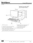
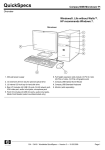
1
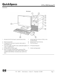
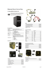
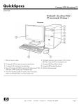
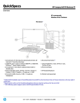
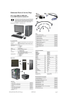
Illustrated Parts & Service Map
HP Pro 3125 Business PC
Minitower Chassis
© 2010 Hewlett-Packard Development Company, L.P. The information contained herein is subject to change without notice. HP shall not be liable for
technical or editorial errors or omissions contained herein. Intel, Pentium,
Intel Inside, and the Intel logo are trademarks or registered trademarks of the
Intel Corporation and its subsidiaries in the U. S. and other countries.
Document Number 621939-001.
1st Edition May 2010.
Cables
1
Front I/O assembly
2
Power switch/LED with holder
508463-001
614496-001
*
SATA optical drive cable with latch, 9.5 inch (240 mm)
614498-001
*
SATA hard drive cable with latch, 6.5 inch (165 mm)
448670-001
*Not shown
Keyboards (not illustrated)
PS/2
USB, Standard
USB SmartCard
USB, low cost
Key Specifications
Processor Type
AMD Sempron™, AMD Athlon™ II X2, AMD Athlon II X3,
AMD Athlon II X4, AMD Phenom™ II X2, AMD Phenom II
X3, AMD Phenom II X4, AMD Phenom II X6
RAM Type
DDR3-SDRAM DIMMs, PC2-10600 (1333 MHz) non-ECC
Maximum RAM Supported
16 GB
Expansion Slots
•
•
•
(3) PCIe x1
(1) PCIe x16
(1) Mini PCI
Graphics Adapter
Integrated ATI Radeon 3000 Graphics
Chipset
AMD 760G
Drive Support
•
•
•
I/O Interfaces
Front: (2) USB ports, microphone, headphone
Rear: (4) USB, (1) VGA, (1) DVI, (1) RJ-45 Ethernet, (1)
SPDIF, (1) audio in, (1) audio out, (1) microphone, (1) surround side, (1) surround rear, (1) surround center/sub
Operating Systems
•
•
•
(2) external 5.25-inch
(1) external 3.5-inch
(2) internal 3.5-inch
Windows 7
Windows XP Professional
FreeDOS
537745-xxx
537746-xxx
537747-xxx
537924-xxx
Arabic[c]
-171
Hungarian
-211
Belgian
-181
International English
-L31
BHCSY[a]
-BL1
Italian
-061
BHCSY[b]
-B41
Norwegian
-091
Bulgaria[b]
-261
Portuguese
-131
Czech[b]
-221
Romanian[b]
-271
Danish[b]
-081
Russian[d]
-251
Finnish
-351
Slovakian
-231
French
-051
Spanish
-071
French Arabic
-DE1
Swedish
-101
German
-041
Swiss
-111
Greek
-151
Turkish
-141
Hebrew
-BB1
U.K.
-031
[a] 537747-xxx only
[b] not for 537747-xxx
[c] 537924-xxx only
[d] not for 537746-xxx
Mass Storage Devices (not illustrated)
Spare Parts
Blu-ray Disc ROM with SuperMulti DVD±R/RW DL Drive
581601-001
DVD±RW and CD-RW SuperMulti DL Combo Drive with LightScribe
581600-001
DVD-ROM drive
581599-001
2 TB hard drive, 7200 rpm
616608-001
1.5 TB hard drive, 7200 rpm
613209-001
1.5 TB hard drive, 5400 rpm
613203-001
1 TB hard drive, 7200 rpm
613202-001
750 GB hard drive, 7200 rpm
613205-001
640 GB hard drive, 7200 rpm
613204-001
500 GB hard drive, 7200 rpm
613208-001
320 GB hard drive, 7200 rpm
613207-001
320 GB hard drive, 5400 rpm
586969-001
250 GB hard drive, 7200 rpm
613206-001
250 GB hard drive, 5400 rpm
586719-001
250 GB USB hard drive
586383-001
160 GB hard drive, 7200 rpm
613201-001
160 GB hard drive, 5400 rpm
419102-001
Hard drive conversion bracket
397117-001
System Unit
1
Front bezel
614499-001
2
Access panel
586372-001
3
Power supply, 300W, PFC
592502-001
4
Chassis
not spared
HP Pro 3125 Illustrated Parts & Service Map, MT chassis
Downloaded from www.Manualslib.com manuals search engine
621939-001
page 1
Miscellaneous Parts
Standard and Optional Boards
System boards with thermal grease, alcohol pad, and CPU socket cover
1
System board, AMD 760G (includes bumper)
614493-001
Memory modules (PC3-10600, CL9)
2
1 GB
576109-001
*
2 GB
576110-001
*
4 GB
585157-001
1
Chassis fan
438741-001
2
Heat sink, AMD class P (includes replacement thermal material)
616606-001
*
Media card reader
480032-001
*
Mouse, optical, Jack Black
537749-001
*
Mouse, laser, Jack Black
570580-001
*
Mouse, optical, Portia
596410-001
*
Mouse, wireless
596412-001
*
Mouse, PS/2, Jack Black
537748-001
*
Rubber feet
370708-001
*
Antenna, dual band dipole, 802.11 a/b/g/n
583345-001
*Not shown
Other boards
*
Agere International 56K LSI v92 modem, includes bracket and 20-inch
(50.8-cm) cable
490689-001
*
USB 3.0 PCIe x1 expansion card, includes bracket
616610-001
*
ATI Radeon HD4350 (RV710D2) PCIe x16 graphics card, 512 MB
586750-001
*
ATI Radeon HD4550 (RV710) PCIe x16 graphics card, 512 MB
584217-001
*
ATI Radeon HD4650 (RV730) PCIe x16 graphics card, 1 GB
578174-001
*
ATI Radeon HD5450 PCIe graphics card, 1 GB
601155-001
*
ATI Radeon HD5570 PCIe graphics card, 1 GB
614507-001
*
ATI Radeon HD5570 (RV830) PCIe graphics card, 2 GB
615792-001
*
GeForce GT320 1-GB PCIe graphics card
615793-001
*
GeForce GT315 1-GB PCIe graphics card
619934-001
*
GeForce GT315 512-MB PCIe graphics card, low profile
614508-001
*
GeForce GT230 1.5-GB PCIe graphics card
586381-001
*
GeForce GT220 1.0-GB PCIe graphics card
614509-001
*
GeForce GT210 512-MB PCIe graphics card
593213-001
*
802.11b/g/n WLAN PCIe adapter
616609-001
*
Intel Gigabit NIC, includes bracket
490367-001
System Board
AMD Athlon II X2 processors with alcohol pad and thermal grease:
*
X4 640, quad core, 2-MB L2 cache, 3.0 GHz C3
614516-001
*
X4 635, quad core, 2-MB L2 cache, 2.9 GHz C3
617834-001
*
X4 630, quad core, 2-MB L2 cache, 2.8 GHz C2
586735-001
*
X4 620, quad core, 2-MB L2 cache, 2.6 GHz, C2
586734-001
*
X3 445, quad core, 2-MB L2 cache, 3.1 GHz, C3
614515-001
*
X3 440, quad core, 2-MB L2 cache, 3.0 GHz, C3
617833-001
System Board Connectors and Jumpers (component location may vary)
*
X3 435, quad core, 2-MB L2 cache, 2.9 GHz, C2
586733-001
J6
PCI slot 1
DIMM4
Memory socket 4
*
X3 425, quad core, 2-MB L2 cache, 2.7 GHz, C2
586732-001
J5
PCI slot 2
P15
Main power connector (24
pin)
*
X2 260, dual core, 2-MB L2 cache, 3.2 GHz, C3
614513-001
J4
PCI slot 3
J18
Power switch connector
*
X2 260u, dual core, 2-MB L2 cache, 1.8 GHz (25W), C3
614514-001
J3
PCI Express X16 connector
CLR CMOS
*
X2 255, dual core, 2-MB L2 cache, 3.1 GHz, C3
617832-001
J9
Password header
*
X2 250, dual core, 2-MB L2 cache, 3.0 GHz, C2
584221-001
Digital line-in/line-out audio con- PSWD
nector
*
X2 245, dual core, 2-MB L2 cache, 2.9 GHz, C2
586731-001
AUDIO
Audio connectors
USB7
USB connector
*
X2 240, dual core, 2-MB L2 cache, 2.8 GHz, C2
584222-001
RJ45
Stacked RJ-45/USB connectors
USB8
USB connector
*
X2 220, dual core, 2-MB L2 cache, 2.8 GHz, C3
611192-001
FAN
System fan connector
SATA2
1st optical drive
*
X2 215, dual core, 2-MB L2 cache, 2.75 GHz, C2
586730-001
J13
Double USB connectors
SATA3
2nd hard drive
VGA/DVI
Stacked DVI/VGA connector
SATA1
1st hard drive
USB connector
SATA4
2nd optical drive
USB connector
AMD Phenom II processors with alcohol pad and thermal grease:
CMOS jumper
*
X6 1055T, quad core, 2-MB L2 cache, 2.8 GHz, C3
617838-001
USB
*
X6 1035T, quad core, 2-MB L2 cache, 2.6 GHz, C3
617837-001
CNI
Digital audio connector
USB5
*
X4 955, quad core, 2-MB L2 cache, 3.2 GHz, C3
614519-001
PU521
CPU power connector
USB6
USB connector
*
X4 945, quad core, 2-MB L2 cache, 3.0 GHz, C2
586741-001
CPU_FAN
CPU/heat sink fan connector
USB3
Front I/O USB connector
*
X4 925, quad core, 2-MB L2 cache, 2.8 GHz (6-MB L3 cache), C3
617836-001
DIMM1
Memory socket 1
USB1
Media card reader connector
*
X4 830, quad core, 2-MB L2 cache, 2.8 GHz (4-MB L3 cache), C3
617835-001
DIMM2
Memory socket 2
BATTERY
RTC battery socket
*
X4 820, quad core, 2-MB L2 cache, 2.8 GHz (4-MB L3 cache), C2
586739-001
DIMM3
Memory socket 3
FRNT_AUD Front panel connector
*
X4 B95, quad core, 2-MB L2 cache, 2.5 GHz, C2
585156-001
*
X3 720, triple core, 1.5-MB L2 cache, 2.8 GHz, C2
581073-001
*
X2 550, dual core, 1-MB L2 cache, 3.1 GHz, C3
614518-001
*
X2 545, dual core, 1-MB L2 cache, 3.0 GHz, C3
614517-001
AMD Sempron processors with alcohol pad and thermal grease:
*
145, single core, 1-MB L2 cache, 2.8 GHz, C3
611196-001
*
140, single core, 1-MB L2 cache, 2.7 GHz, C2
586742-001
* Not shown
HP Pro 3125 Illustrated Parts & Service Map, MT chassis
Downloaded from www.Manualslib.com manuals search engine
621939-001
page 2
Computer Setup
POST Text Messages
Basic system information regarding system information, setup, power management, hardware,
and passwords is maintained in the Setup Utility held in the system ROM. The Setup Utility is
accessed by pressing the F10 key when prompted (on screen) to do so during the boot sequence.
If the screen prompt opportunity is missed, a restart will be necessary...
This section lists the error messages and the various audible sequences that you may encounter
during Power-On Self-Test (POST) or computer restart, the probable source of the problem, and
steps you can take to resolve the error condition.
The section includes some text messages that may be encountered during POST.
Computer Setup Menu
Control Panel Message
Description
Heading
Default BIOS settings have
been loaded due to BIOS
update or checksum issue.
Press <F10> to enter Setup.
Otherwise, allow the PC to
continue.
BIOS has been updated or Press F10 to enter Computer
returned to default settings. Setup and configure the system or ignore the message and
accept the default settings.
CPU fan is not connected
or may have malfunctioned.
1. Reseat the CPU fan.
Main
Advanced
Power
Boot
Exit
Option / Description
Recommendation
System Time
Allows you to set system time.
System Date
Allows you to set system date.
System IDs
Allows you to view or change the following by pressing
Enter: Product name, serial number, UUID, SKU, Family name (view only), Feature byte, Build ID.
Language
Allows you to select the language.
Floppy Diskette A
Allows you to set to Disabled, 1.44 MB 3.5”, Not
Installed.
ERROR: CPU Fan Has Failed.
PC will automatically power
down in a few seconds. Service
PC immediately to prevent
damage to CPU.
1st Drive
2nd Drive
3rd Drive*
4th Drive*
Allow you to: Enable/disable port configuration, view
capacity, transfer mode. Also allows you to run HDD
self-test for selected channel: SMART status check,
SMART short self test, SMART extended self test.
ERROR: System Fan Has
Failed. Service PC to prevent
damage to the system. Press F2
to continue.
System fan is not
connected or may have
malfunctioned.
1. Reseat the system fan.
System Information
Allows you to view installed memory, memory banks 14, BIOS revision, core version.
ERROR: Unsupported CPU
installed. PC will automatically
power down in a few seconds.
Install a CPU supported by
your system.
CPU Type
View only.
Recently installed CPU is
not supported by the
system.
CPU Speed
View only.
Cache RAM (L2)
View only.
Cache RAM (L3)
View only.
Primary Video
Adapter
Allows you to select boot display device when more
than 2 video options are offered by system: Integrated
(Onboard), PCI-E.
SATA1 Controller
Allows you to disable/enable the SATA controller.
SATA1 Controller
Mode
If SATA1 Controller is enabled, allows you to set the
mode to: IDE, AHCI
USB Ports
Allows you to disable/enable individual USB ports.
Onboard LAN
Allows you to disable/enable onboard LAN controller.
Onboard LAN Boot
ROM
Disable/enable the boot ROM of the onboard LAN chip.
Supervisor Password
Allows you to view the supervisor password.
User Password
Allows you to view the user password. Only displays in
a Supervisor password is set.
Change Supervisor
Password
Allows you to establish, disable, or change the supervisor password.
Change User Password
Allows you to establish, disable, or change the user password. Only displays in a Supervisor password is set.
Onboard Audio
Allows you to set the onboard audio to: Enabled, Disabled, Auto.
After AC Power Failure
Allows you to select system restart behavior after power
loss: Stay off, Power on, Auto.
S5 Maximum Power
Savings
Disables/enables S5 Maximum Power Savings. Enabling
this feature reduces the power of this system as much as
possible in the S5 state. This feature must be disabled if
you want to enable Wake on LAN from S5.
WOL in S5
Disables/enables limited Wake on LAN from S5. Note
that the computer can only wake from S5 during a normal shutdown event. The S5 Maximum Power Savings
feature must be disabled in order to enable limited Wake
on LAN from S5.
2. Reseat the fan cable.
3. Replace the CPU fan.
2. Reseat the fan cable.
3. Replace the system fan.
The machine cover has been
Computer cover was
removed since last system star- removed since last system
tup. Please ensure that any sys- startup.
tem access was authorized.
Press <F2> to continue.
On some models no action is
required. On other models
you must clear the warning
message in the Computer
Setup utility. To do so, restart
the computer and press F10
before the computer boots to
the operating system to enter
the Computer Setup utility. In
the PC Health menu, open the
Chassis Opened Warning item
and select Clear. Save your
changes and exit the
Computer Setup utility.
Hard disk failure is imminent.
Please back up your hard disk
and have it replaced! Press
<F10> for Setup, <F2> to continue.
Hard drive is about to fail.
Back up data on the hard drive
and replace the drive.
Warning: Changing setup
options while resuming from
Hibernate may cause your system to fail to resume.
Warning message.
No recommended action.
POST Audible Codes
Beeps
Meaning
Recommended Action
1 short beep and 1 long beep
followed by a long pause
Bad memory or
memory configuration error.
CAUTION: To avoid damage to the
DIMMs or the system board, you must
unplug the computer power cord
before attempting to reseat, install, or
remove a DIMM module.
1. Reseat DIMMs.
2. Ensure that the DIMMs are installed
in the correct memory sockets.
3. Replace DIMMs one at a time to
isolate the faulty module.
4. Replace third-party memory with
HP memory.
5. Replace the system board.
NX (No Execute)
Disable/enables the processors NX feature.
Virtualization Technology
Disable/enable.
Disable/enable POST diagnostic messages display during boot.
2 short beeps and 1 long
beep followed by a long
pause
Graphics card initialization failed.
1. Reseat the graphics card.
Boot-time Diagnostic
Screen
(Boot Device Priority)
1st Boot Device,
2nd Boot Device,
3rd Boot Device,
4th Boot Device
Allows you to set device group boot priority: CD-ROM
group, Hard drive group, Floppy group, Network boot
group. MS-DOS drive lettering assignments maybe
apply after a non-MS-DOS operating system has started.
3 short beeps and 1 long
beep followed by a long
pause
CPU configuration
error or invalid CPU
detected before
graphics card initialized.
1. Reseat the processor.
Floppy Group Boot
Priority
Specifies boot device priority within removable devices.
NOTE: This computer does not support floppy drives.
1 short beep followed by a
short pause
Specifies boot device priority within CD/DVD drives.
No legacy floppy
drive or optical drive
found.
1. Reseat floppy or optical drive.
CD-ROM Boot Priority
Specifies boot device priority within hard drives.
No floppy diskette or
CD found.
Insert diskette or CD.
Hard Drive Boot Priority
Network Group Boot
Priority
Specifies boot device priority within bootable network
devices.
2 short beeps followed by a
long pause
OR
1 short beep followed by a
long pause
Exit Saving Changes
Press Enter to exit saving changes.
3 short beeps followed by a
three second pause
Press Enter to exit discarding changes.
Flashing not ready
(missing utility or
BIOS image file,
etc.)
Flash the BIOS with the proper BIOS
flash utility available from HP.
Exit Discarding
Changes
4 short beeps followed by a
three second pause
Flashing operation
Flash the BIOS with the proper BIOS
has failed (checksum flash utility available from HP.
error, corrupted
image, etc.)
5 short beeps followed by a
three second pause
BIOS recovery was
successful
Load Setup Defaults
Press Enter to load setup defaults.
Discard Changes
Press Enter to discard changes.
Save Changes
Press Enter to save changes.
HP Pro 3125 Illustrated Parts & Service Map, MT chassis
Downloaded from www.Manualslib.com manuals search engine
621939-001
2. Replace the graphics card.
3. Replace the system board.
2. Replace the processor.
3. Replace the system board.
2. Replace floppy or optical drive.
No action required.
page 3
Resetting the password jumper
System Recovery Options
1. Shut down the operating system properly, then turn off the computer and any external devices,
and disconnect the power cord from the power outlet.
You should attempt a System Recovery in the following order:
2. With the power cord disconnected, press the power button again to drain the system of any
residual power.
2. Through the hard disk drive, by pressing the F11 key on the keyboard during system startup.
3. Through recovery discs that you create.
4. Through recovery discs purchased from HP Support.
3. Remove the access panel.
1. Through the hard disk drive, from the Windows Start menu.
4. Locate the header and jumper.
5. On systems with 3-pin jumpers, remove the jumper from pins 1 and 2. Place the jumper on
pins 2 and 3. On systems with 2-pin jumpers, remove the jumper from pins 1 and 2.
6. Replace the access panel.
7. Reconnect the external equipment.
8. Plug in and turn on power. Allow the operating system to start. This clears the current
passwords and disables the password features.
9. To establish new passwords, repeat steps 1 - 4, replace the password jumper on pins 1 and 2,
then repeat steps 6 - 8. Establish new passwords in Computer Setup.
Clearing and Resetting the CMOS
The computer’s configuration memory (CMOS) stores information about the computer’s
configuration. The CMOS jumper resets CMOS but does not clear the supervisor and user
passwords.
CAUTION: Resetting the CMOS jumper will reset CMOS values to factory defaults. It is
important to back up the computer CMOS settings before resetting them in case they are needed
later. Back up is easily done through Computer Setup.
1. Turn off the computer and any external devices, and disconnect the power cord from the
power outlet.
2. Disconnect the keyboard, monitor, and any other external equipment connected to the
computer.
3. Remove the access panel.
4. Locate the header and jumper.
CAUTION: Make sure you have disconnected the AC power cord from the wall outlet.
Clearing the CMOS while power is connected can damage the system board.
System Recovery from the Windows Start Menu
CAUTION: System Recovery deletes all data and programs you created or installed. Back up
any important data to a removable disc.
If the computer is working and Windows is responding, use these steps to perform a System
Recovery.
1. Turn off the computer.
2. Disconnect all peripheral devices from the computer except the monitor, keyboard, and
mouse.
3. Turn on the computer.
4. Click the Start button, click All Programs, click Recovery Manager, and then click Recovery Manager. If prompted, click Yes to allow the program to continue.
5. Under I need help immediately, click System Recovery.
6. Select Yes, and then click Next. The computer restarts.
NOTE: If the system does not detect a recovery partition, it prompts you to insert a recovery
disc. Insert the disc, select Yes, and then click Next to restart the computer and run Recovery
Manager from the recovery disc. Insert the remaining recovery discs when prompted.
7. When the computer restarts, once again you see the Recovery Manager welcome screen.
Under I need help immediately, click System Recovery. If you are prompted to back up
your files, and you have not done so, select Back up your files first (recommended), and
then click Next. Otherwise, select Recover without backing up your files, and then click
Next.
8. System Recovery begins. After System Recovery is complete, click Finish to restart the computer.
9. Complete the registration process, and wait until you see the desktop.
10.Turn off the computer, reconnect all peripheral devices, and turn the computer back on.
5. Remove the jumper from pins 1 and 2. Place the jumper on pins 2 and 3.
6. Place the jumper back on pins 1 and 2.
7. Replace the access panel.
System Recovery at System Startup
8. Reconnect the external equipment.
CAUTION: System Recovery deletes all data and programs you created or installed. Back up
any important data to a removable disc.
If Windows is not responding, but the computer is working, follow these steps to perform a
System Recovery.
9. Plug in and turn on power.
NOTE: You will receive POST error messages after clearing CMOS and rebooting advising you
that configuration changes have occurred. Use Computer Setup to reset any special system
setups along with the date and time.
Hewlett-Packard Vision Diagnostics
The Hewlett-Packard Vision Diagnostics utility allows you to view information about the
hardware configuration of the computer and perform hardware diagnostic tests on the
subsystems of the computer. The utility simplifies the process of effectively identifying,
diagnosing, and isolating hardware issues.
Use HP Vision Diagnostics to determine if all the devices installed on the computer are
recognized by the system and functioning properly.
To access HP Vision Diagnostics, you must create a Recovery Disc Set then boot to the CD
containing the utility. It can also be downloaded from http://www.hp.com and either burned to
CD or installed to a USB flash drive.
1. Turn off the computer. If necessary, press and hold the On button until the computer turns off.
2. Disconnect all peripheral devices from the computer, except the monitor, keyboard, and
mouse.
3. Press the On button to turn on the computer.
4. As soon as you see the initial company logo screen appear, repeatedly press the F11 key on
the keyboard until the Windows is Loading Files… message appears on the screen.
5. Under I need help immediately, click System Recovery.
6. If you are prompted to back up your files, and you have not done so, select Back up your
files first (recommended), and then click Next. Otherwise, select Recover without backing
up your files, and then click Next.
7. System Recovery begins. After System Recovery is complete, click Finish to restart the computer.
8. Complete the registration process, and wait until you see the desktop.
9. Turn off the computer, reconnect all peripheral devices, and turn the computer back on.
Downloading the Latest Version of HP Vision Diagnostics
1. Go to http://www.hp.com.
System Recovery from Recovery Discs
2. Click the Software & Drivers link.
3. Select Download drivers and software (and firmware).
4. Enter your product name in the text box and press the Enter key.
5. Select your specific computer model.
6. Select your OS.
7. Click the Diagnostic link.
8. Click the Hewlett-Packard Vision Diagnostics link.
9. Click the Download button.
NOTE: The download includes instructions on how to create the bootable CD.
CAUTION: System Recovery deletes all data and programs you created or installed. Back up
any important data to a removable disc.
To perform a System Recovery using recovery discs:
1. If the computer is working, create a backup DVD containing all the data files you want to
save, and then remove the backup disc from the drive tray.
Microsoft System Restore
If you have a problem that might be due to software that was installed on your computer, use
System Restore to return the computer to a previous restore point. You can also set restore points
manually.
NOTE: Always use this System Restore procedure before you use the System Recovery
program.
NOTE: Some features might not be available on systems that are shipped without a version of
Microsoft Windows.
To start a System Restore:
2. Insert recovery disc #1 into the DVD drive tray, and close the tray.
3. If the computer works, click the Start button, click the Arrow button next to Shut Down, and
then click Shut Down. Or, if the computer is not responding, press and hold the On button for
approximately 5 seconds, or until the computer turns off.
4. Disconnect all peripheral devices from the computer except the monitor, keyboard, and
mouse.
5. Press the On button to turn on the computer. If you are prompted to choose between running
System Recovery from disc or from hard drive, select Run program from disc, and then
click Next.
6. Under I need help immediately, click Factory Reset.
7. If you are prompted to back up your files, and you have not done so, select Back up your
files first (recommended), and then click Next. Otherwise, select Recover without backing
up your files, and then click Next.
8. If you are prompted to insert the next recovery disc, do so.
9. When the Recovery Manager is finished, remove all recovery discs from the system.
10.Click Finish to restart the computer.
1. Close all open programs.
2. Click the Start button, right-click Computer, and then click Properties.
3. Click System protection, System Restore, click Next, and then follow the on-screen instructions.
To add restore points manually:
1. Close all open programs.
2. Click the Start button, right-click Computer, click Properties, and then click System protection.
3. Under Protection Settings, select the disk for which you want to create a restore point.
4. Click Create, and then follow the on-screen instructions.
System Recovery
System Recovery completely erases and reformats the hard disk drive, deleting all data files you
have created, and then reinstalls the operating system, programs, and drivers. However, you
must reinstall any software that was not installed on the computer at the factory. This includes
software that came on media included in the computer accessory box, and any software
programs installed after purchase.
You must choose one of the following methods to perform a System Recovery:
• Recovery Image. Run the System Recovery from a recovery image stored on your hard disk
drive. The recovery image is a file that contains a copy of the original factory-shipped software.
NOTE: The recovery image uses a portion of the hard disk drive that cannot be used for
data storage.
• Recovery Discs. Run the System Recovery from a set of recovery discs that you create from
files stored on your hard disk drive or purchased separately.
HP Pro 3125 Illustrated Parts & Service Map, MT chassis
Downloaded from www.Manualslib.com manuals search engine
621939-001
page 4