1
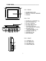
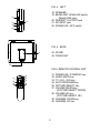
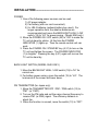
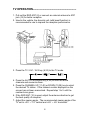
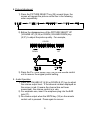
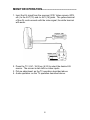
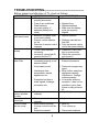
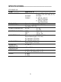
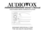
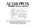
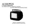
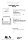
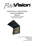
4”/6” TFT- LCD
COLOR TV
CTV-5040 / 60
INSTRUCTION MANUAL
91-S2-1005
RECOMMENDED GUIDELINES FOR THE USE OF
A VIDEO MONITOR/TV IN A MOTOR VEHICLE
• A VIDEO MONITOR/TV is designed for rear passenger viewing
only. This product may only be installed in the rear seat
compartment of the vehicle, out of the driver’s view.
• Installation in any other area of the vehicle, including anywhere
within the driver’s view, is illegal in most states, provinces and
countries and may lead to driver distraction resulting in an
accident, injury and/or death. If you are unsure of regulations
regarding this, please consult your local laws to determine how
this applies to you.
• Users should be aware of possible noise distraction caused by the
use of the product and should carefully monitor the volume so as
not to interfere with the driver’s attention to surrounding traffic
conditions.
FUNCTION-------------------------------------------------------1
2
FIG. 1 FRONT
1. POWER INDICATOR
1. REMOTE CONTROL SENSOR
1. SCREEN
3
FIG. 2 TOP
1.
1.
1.
1.
1.
12
1.
4
5 6 7
1.
1.
1.
8 9 10 11
POWER ON / STAND BY key
AUTO PROGRAM key
TV / AV1 / AV2 key
PICTURE SELECT key
VOLUME DOWN key
(PICTURE SELECT DOWN)
VOLUME UP key
(PICTURE SELECT UP)
CHANNEL DOWN key
CHANNEL UP key
ROD ANTENNA
FIG. 3 RIGHT
14.
15.
15.
15.
13
14
15
16
17
1
ANTENNA jack
AV1 INPUT jack
AV2 INPUT jack
EARPHONE jack
FIG. 4 LEFT
18. SPEAKER
19. BACKLIGHT HIGH/LOW switch
(Model 5040 only)
20. DIVERSITY OUTPUT jack
21. DC INPUT jack
22. POWER ON / OFF switch
19
18
20
21
22
FIG. 5 BACK
23
23. STAND
24. FIXING NUT
LIFT
24
FIG.6 REMOTE CONTROL UNIT
31. POWER ON / STAND BY key
32. AUDIO MUTE key
33. TV / AV1 / AV2 key
34. AUTO PROGRAM key
35. PICTURE SELECT key
37. VOLUME DOWN key
(PICTURE SELECT DOWN)
38. VOLUME UP key
(PICTURE SELECT UP)
39. CHANNEL DOWN key
40. CHANNEL UP key
32
31
33
34
35
37
39
38
40
2
INSTALLATION-------------------------------------------------POWER
1. One of the following power sources can be used.
1) AC power adapter.
2) Car battery (with car cord connected).
3) 8 x UM-3 batteries (optional battery box used). For
longer operation time, the alkaline batteries are
recommended and move the BACKLIGHT HIGH / LOW
switch (19) to “LO” for power saving. (Model 5040 only)
2. Move the POWER ON / OFF switch (22) to “ON” to make the
TV unit at stand-by status. At this time the POWER
INDICATOR (1) lights up. Then the remote control unit can
work.
3. Press the POWER ON / STAND BY key (4,31) to turn on the
TV unit and lighten the screen. The POWER INDICATOR
(1) is brighter. Pressing the key (4,31) again will recover the
TV unit to stand by.
BACK LIGHT SWITCH (MODEL 5040 ONLY)
1. Move the BACKLIGHT HIGH / LOW switch (19) to “HI” for
normal use.
2. For battery power saving, move the switch (19) to “LO”. The
luminance of the screen will lower down.
FM TRANSMITTER (for Japan only)
1. Move the TRANSMITTER OFF / FM1 / FM2 switch (13) to
“FM1” (or “FM2”).
2. Turn on the FM radio and set the same channel frequency to
receive FM1 (or FM2) signal. The efficiency distance is
about 5m.
3. When the function is unused, move the switch (13) to “OFF”.
3
TV OPERATION------------------------------------------------1. Pull out the ROD ANT (2) or connect an external antenna to ANT
jack (14) for better reception.
2. Used in the vehicle, the diversity unit (with boost function) is
recommended to use to improve the reception performance.
3. Press the TV / AV1 / AV2 key (6,33) to the TV mode.
4. Press the AUTO PROGRAM key (5,34) to scan the whole
channels and memorize them.
5. Press the CHANNEL UP (11,40) or DOWN (10,39) key to select
the desired TV station. If the channel number displayed on the
screen has not been memorized. Repeat step 1 to 5 until the
number turns green.
6. If the ROD ANT (12) is used, adjust the antenna direction to get
the best quality of reception.
7. Adjust the viewing angle. The recommended viewing angle of the
TV unit is +30° ~ -10° vertical and +45° ~ -45° horizontal.
4
8. Picture Adjustment
1) Press the PICTURE SELECT key (35) several times, the
screen will appear the picture control bar in the following
order sequentially.
2) Before the disappearance of the PICTURE SELECT UP
(VOLUME UP) (9,38) or DOWN (VOLUME DOWN) key
(8,37), to adjust the picture quality. For example,
COLOR
DOWN
UP
3) Press the PICTURE RESET key (36) on the remote control
unit to recover the original picture setting.
9. Audio Operation
1) Press the VOLUME UP (9,38) or DOWN (8,37) key to adjust
the volume output level. If the channel number displayed on
the screen is red (it means the channel has not been
memorized), the volume control is in vain.
2) For earphone use, insert the earphone plug into the EAR
jack (17).
3) No volume output when the MUTE key (32) on the remote
control unit is pressed. Press again to recover.
5
MONITOR OPERATION--------------------------------------1. Input the AV signal from the sources (VCR, Video camera, GPS,
etc.) to the AV1 (15) and /or AV2 (16) jacks. The yellow terminal
of the AV cord connects with the video signal; the white terminal
with audio.
2. Press the TV / AV1 / AV2 key (6,33) to select the desired AV
source. The screen is dark with no video inputs.
3. Picture adjustment: as the TV operation described above.
4. Audio operation: as the TV operation described above.
6
IMPORTANT NOTES------------------------------------------1. Do not expose to temperature extremes or direct sunlight. (See
specifications)
2. Avoid dust and wet.
3. Avoid dropping and strong impact.
4. Turn power off and unplug the adapter when not in use or
thundering.
5. Never watch while driving a vehicle.
6. Never attempt your own maintenance.
7
TROUBLESHOOTING----------------------------------------Before assuming malfunction of TV, check as follows:
SYMPTOMS
No power
•
•
•
•
Remote control
unit cannot work
•
•
•
No picture and
sound
•
•
Blurry picture
and noise
•
•
Sound heard but
picture all white
or dark
Sound heard but
color light
Picture visible
but no sound
POSSIBLE CAUSES
AC adapter or car cord not
properly connected
Fuse of car cord blown
Dead batteries
Incorrect polarity of
batteries (battery box
used)
Batteries unloaded, dead
or incorrect polarity
Remote control distance
too far.
Direction of remote control
improper
TV/AV1/AV2 selected
incorrectly
Incorrectly connected AV
sources and the TV
External antenna not
connected properly or rod
antenna folded
Not properly tuned.
•
•
•
•
•
•
•
•
•
•
•
WHAT TO DO
Connect correctly
Replace fuse
Replace batteries
Make sure the battery
poles are properly
aligned.
replace batteries
Distance must be less
than 2M.
Point the remote control
unit to the sensor directly
Press the TV/AV1/Av2
key to correct mode
Check the connection
and correct it
Check the connection.
Extend rod antenna.
•
Interference from
automobiles, electric
appliances, etc.
•
•
Reception bad due to
weak signals, buildings,
mountains, etc.
•
•
Brightness control not set
correctly
•
Press auto program key
again.
Move further away from
appliances causing
interference. Change
antenna position.
In locations with poor
reception, it may not be
possible to get a clear
picture or any picture at
all.
Adjust brightness
•
Color control not set
correctly.
Mute function working.
Volume control turned too
low
Earphone inserted
•
Adjust color.
•
•
Mute off.
Turn volume up.
•
Disconnect earphone.
•
•
•
8
SPECIFICATIONS----------------------------------------------CTV-5040 / 60
TYPE
DISPLAY SCREEN
BACK LIGHT
POWER SUPPLY
POWER CONSUMPTION
RECEPTION CHANNELS
INPUT TERMINALS
OUTPUT TERMINALS
OPERATION
TEMPERATURE
STORAGE
TEMPERATURE
DIMENSIONS
WEIGHT
Color LCD TV
SIZE
4 inches (82.1 x 61.7mm)(W x H)
6 inches (112.9 x 84.7mm) (W x H)
ELEMENT
TFT-LCD
FORMAT
4”: 480 (W) x 234 (H)
Total 112,320 dots
6”: 720 (W) x 234 (H)
Total 168,480 dots
Cold cathode fluorescent lamp
AC adapter (AC 120V 60 Hz DC 12V)
Car battery (DC 12V)
DC 12V
4”: 7W
6”: 11W
VHF-L
CH 2 ~ 6
VHF-H
CH 7 ~ 13
UHF
CH 14 ~ 69
External power jack (DC IN 12 ~ 14V)
External antenna jack (3.5∅ mm)
AV1 input jack (3.5∅ mm)
AV2 input jack (3.5∅ mm)
Diversity jack (3.5∅ mm)
Earphone jack (3.5∅ mm)
5° ~ 40° C
-20° ~ +60° C
4”: 150 x 116 x 45mm (W x H x D)
6”: 180 x 145 x 48mm (W x H x D)
4”: 460g
6”: 650g
9
ACCESSORY LIST--------------------------------------------Description
AVT-988 9” Color Television with Remote (12V)
AVT-597 5” Color Television with Remote (12V)
AVT-1498 13” Color Television with Remote (12V)
AVP-7000 Video Cassette Player (12V)
AVP-7285 Video Cassette Player (12V)
Wireless Headphone Kit: Includes 2 sets Wireless
Headphones and Transmitter
BPA-501-12 4 Amp Adapter for use with AVT-988 9” and
AVT-1498 13” Televisions
AC2A- 2 Amp Adapter for use with AVT-597 5” TV and
AVP-7000 Video Cassette Player
Unified Remote Control
VAC-21- 12 Volt Corded Vacuum
AVF-1 12 Volt Rechargeable Flashlight
HP-175 Headphones with Pivoting Ear Cup
HP-275 Headphones with Volume Control on Cord
HP-375 Studio Quality Headphones
Part Number
AVT988
AVT597
AVT1498
AVP7000
AVP7285
WRFKIT1
0891412
0891436
0892325
VAC21
AVF1
HP175
HP275
HP375
Unlike household electronics, all of our products have been
specifically designed and tested for the mobile environment and are
only available through ASA. To order any of these products, please
contact Audiovox Specialized Applications at
www.asaelectronics.com or 800-688-3135.
10