1
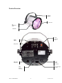
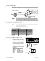
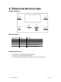
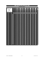
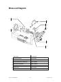
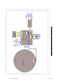
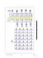
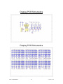
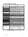
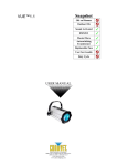
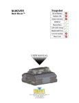
Vue™ 4.1
Snapshot
OK on Dimmer
Outdoor OK
Sound Activated
DMX512
Master/Slave
Autoswitching
Transformer
Replaceable Fuse
User Serviceable
Duty Cycle
USER MANUAL
3000 N 29th Ct, Hollywood, FL 33020 U.S.A.
(800) 762-1084 – (954) 929-1115
FAX (954) 929-5560
www.chauvetlighting.com
TABLE OF CONTENTS
1. Before You Begin ...................................................................................................................................... 3
What is included.............................................................................................................................................. 3
Unpacking Instructions .................................................................................................................................... 3
AC Power ........................................................................................................................................................ 3
Contact Us ...................................................................................................................................................... 3
Safety Instructions .......................................................................................................................................... 4
2. Introduction ............................................................................................................................................... 5
Features .......................................................................................................................................................... 5
DMX Channel Summary ................................................................................................................................. 5
Product Overview............................................................................................................................................ 6
3. Setup .......................................................................................................................................................... 7
Fuse Replacement .......................................................................................................................................... 7
Fixture Linking................................................................................................................................................. 7
Data Cabling ................................................................................................................................................... 7
DMX Data Cable ............................................................................................................................................. 7
Cable Connectors ........................................................................................................................................... 8
3-Pin to 5-Pin Conversion Chart ..................................................................................................................... 8
Setting up a DMX Serial Data Link.................................................................................................................. 8
Master/Slave Fixture Linking ........................................................................................................................... 9
Mounting ......................................................................................................................................................... 9
Orientation ...................................................................................................................................................... 9
Rigging ............................................................................................................................................................ 9
Slide-Rails Adjustment .................................................................................................................................... 9
4. Operating Instructions............................................................................................................................ 10
Menu Functions ............................................................................................................................................ 10
Operation ...................................................................................................................................................... 11
Stand-Alone Mode (Sound-Active, Auto Mode): ........................................................................................... 11
Master/Slave Mode (Master Sound, Master Auto): ....................................................................................... 11
DMX Mode .................................................................................................................................................... 11
DMX Channel Values .................................................................................................................................... 12
Setting the starting address .......................................................................................................................... 14
DMX Quick Reference Chart......................................................................................................................... 14
Blow-out Diagram ......................................................................................................................................... 16
Vue 4.1 Maintenance Guide.......................................................................................................................... 21
Technical Support ......................................................................................................................................... 22
5. Appendix.................................................................................................................................................. 22
DMX Primer .................................................................................................................................................. 22
General Maintenance .................................................................................................................................... 23
Returns Procedure ........................................................................................................................................ 23
Claims ........................................................................................................................................................... 23
Technical Specifications ............................................................................................................................... 24
Vue™ 4.1 User Manual
2
7/11/2008 11:57 AM
1. BEFORE YOU BEGIN
What is included
¾
¾
¾
¾
1 x Vue™ 4.1
Power Cord
Warranty Card
User Manual
Unpacking Instructions
Immediately upon receiving a fixture, carefully unpack the carton, check the contents to ensure that
all parts are present, and have been received in good condition. Notify the shipper immediately and
retain packing material for inspection if any parts appear damaged from shipping or the carton itself
shows signs of mishandling. Save the carton and all packing materials. In the event that a fixture
must be returned to the factory, it is important that the fixture be returned in the original factory box
and packing.
AC Power
This fixture has an auto-switching power supply that can accommodate a wide range of input
voltages. The only thing necessary to do before powering on the unit is to make sure the line voltage
you are applying is within the range of accepted voltages. This fixture will accommodate between
100V and 240V AC 50-60 Hz. All fixtures must be powered directly off a switched circuit and cannot
be run off a rheostat (variable resistor) or dimmer circuit, even if the rheostat or dimmer channel is
used solely for a 0% to 100% switch.
Contact Us
World Wide
General Information
CHAUVET
th
3000 North 29 Court
Hollywood, FL 33020
voice: 954.929.1115
fax:
954.929.5560
toll free: 800.762.1084
Technical Support
CHAUVET
th
3000 North 29 Court
Hollywood, FL 33020
voice: 954.929.1115 (Press 4)
fax:
954.929.5560 (Attention: Service)
World Wide Web
www.chauvetlighting.com
Vue™ 4.1 User Manual
3
7/11/2008 11:57 AM
Safety Instructions
Please read these instructions carefully, which includes important
information about the installation, usage and maintenance of this
product.
•
•
•
•
•
•
•
•
•
•
•
•
•
•
Caution!
Please keep this User Guide for future consultation. If you sell the unit to another user, be sure that
they also receive this instruction booklet.
Always make sure that you are connecting to the proper voltage, and that the line voltage you are
connecting to is not higher than that stated on the decal or rear panel of the fixture.
This product is intended for indoor use only! (If applicable)
To prevent risk of fire or shock, do not expose fixture to rain or moisture. Make sure there are no
flammable materials close to the unit while operating.
The unit must be installed in a location with adequate ventilation, at least 20in (50cm) from adjacent
surfaces. Be sure that no ventilation slots are blocked.
Always disconnect from power source before servicing or replacing lamp or fuse and be sure to
replace with same lamp source.
Secure fixture to fastening device using a safety chain. Never carry the fixture solely by its head. Use
its carrying handles.
Maximum ambient temperature (Ta) is 104°F (40°C). Do not operate fixture at temperatures higher
than this.
In the event of a serious operating problem, stop using the unit immediately. Never try to repair the
unit by yourself. Repairs carried out by unskilled people can lead to damage or malfunction. Please
contact the nearest authorized technical assistance center. Always use the same type spare parts.
Never connect the device to a dimmer pack.
Make sure the power cord is never crimped or damaged.
Never disconnect the power cord by pulling or tugging on the cord.
Avoid direct eye exposure to the light source while it is on.
Do not daisy chain power to more than 25 units on 120V operation. (If applicable)
There are no user serviceable parts inside the unit. Do not open the housing or
attempt any repairs yourself. In the unlikely event your unit may require service,
please contact CHAUVET at: 954-929-1115.
Vue™ 4.1 User Manual
4
7/11/2008 11:57 AM
2. INTRODUCTION
Features
•
•
•
•
•
•
9-channel DMX-512 LED rotating moon flower
Blackout/static/strobe
Individual control of red, green, blue, white and amber LEDs within each cluster
(6 total)
Variable speed of motor
Built-in automated programs via DMX
Built-in sound activated programs via master/slave or DMX
Additional Features
•
•
Adjustable hanging bracket with slide rail
Additional power output: max 25 units @ 120V (see manual for details)
DMX Channel Summary
CHANNEL FUNCTION
1
Operating mode
2
Cluster 1
3
Cluster 2
4
Cluster 3
5
Cluster 4
6
Cluster 5
7
Cluster 6
8
Strobe
9
Motor Rotation speed
Vue™ 4.1 User Manual
5
7/11/2008 11:57 AM
Product Overview
Hanging
Bracket
Front Lens
Tilt
Adjustment
Knob
Slide Rail
Sound
Sensitivity
Knob
Digital
Display
Microphone
Power
Output
Connector
DMX Input
Connector
AC Power Input
& Fuse
DMX
Output
Connector
Vue™ 4.1 User Manual
6
7/11/2008 11:57 AM
3. SETUP
Disconnect the power cord before replacing a fuse and always
replace with the same type fuse.
Fuse Replacement
With a flat head screwdriver wedge the fuse
holder out of its housing. Remove the damaged
fuse from its holder and replace with exact
same type fuse. Insert the fuse holder back in
The fuse is located
inside this
compartment.
Remove using a flat
head screwdriver.
its place and reconnect power.
Fixture Linking
You will need a serial data link to run light shows of one or more fixtures using a DMX-512 controller
or to run synchronized shows on two or more fixtures set to a master/slave operating mode. The
combined number of channels required by all the fixtures on a serial data link determines the number
of fixtures the data link can support.
Important:
Fixtures on a serial data link must be daisy chained in one single line. To comply with the EIA-485
standard no more than 32 devices should be connected on one data link. Connecting more than 32
fixtures on one serial data link without the use of a DMX optically-isolated splitter may result in
deterioration of the digital DMX signal.
Maximum recommended serial data link distance: 500 meters (1640 ft.)
Maximum recommended number of fixtures on a serial data link: 32 fixtures
Data Cabling
To link fixtures together you must obtain data cables. You can purchase CHAUVET-certified DMX
cables directly from a dealer/distributor or construct your own cable. If you choose to create your own
cable please use data-grade cables that can carry a high quality signal and are less prone to
electromagnetic interference.
D MX DA TA CAB LE
Use a Belden© 9841 or equivalent cable which meets the specifications for EIA RS-485 applications.
Standard microphone cables cannot transmit DMX data reliably over long distances. The cable will
have the following characteristics:
2-conductor twisted pair plus a shield
Maximum capacitance between conductors – 30 pF/ft.
Maximum capacitance between conductor and shield – 55 pF/ft.
Maximum resistance of 20 ohms / 1000 ft.
Nominal impedance 100 – 140 ohms
Vue™ 4.1 User Manual
7
7/11/2008 11:57 AM
CAB LE C ONN ECTORS
Cabling must have a male XLR connector on one end and a female XLR connector on the other end.
1
3
2
DMX connector configuration
COMMON
INPUT
1
3
2
CAUTION
1
3
2
DMX +
DMX
-
Resistance 120
ohm 1/4w between
pin 2 (DMX -) and
pin 3 (DMX +) of
the last fixture.
OUTPUT
Termination reduces signal errors. To
avoid signal transmission problems
and interference, it is always
advisable to connect a DMX signal
terminator.
Do not allow contact between the common and the fixture’s chassis ground. Grounding the common
can cause a ground loop, and your fixture may perform erratically. Test cables with an ohm meter to
verify correct polarity and to make sure the pins are not grounded or shorted to the shield or each other.
3-PIN TO 5- PIN CON VER SION CHAR T
Note!
If you use a controller with a 5 pin DMX output connector, you will need to use a 5 pin to 3 pin adapter.
CHAUVET Model No: DMX5M, or DMX5F.
The chart below details a proper cable conversion:
3 PIN TO 5 PIN CONVERSION CHART
Conductor
3 Pin Female (output)
5 Pin Male (Input)
Ground/Shield
Pin 1
Pin 1
Data ( - ) signal
Pin 2
Pin 2
Data ( + ) signal
Pin 3
Pin 3
Do not use
Do not use
Do not use
Do not use
Universal DMX Controller
Setting up a DMX Serial Data Link
1. Connect the (male) 3 pin connector side of
the DMX cable to the output (female) 3 pin
connector of the controller.
2. Connect the end of the cable coming from
the controller which will have a (female) 3
pin connector to the input connector of the
next fixture consisting of a (male) 3 pin
connector.
This drawing provides a
general illustration of the
DMX Input/Output panel of
a lighting fixture.
3. Then, proceed to connect from the output
as stated above to the input of the following
fixture and so on.
CHAUVET Certified DMX Data Cables
Vue™ 4.1 User Manual
Order Code
Description
DMX1.5
DMX Cable 1.5m/4.9ft
DMX4.5
DMX Cable 4.5m/14.8ft
DMX10
DMX Cable 10m/32.8ft
8
Continue the link
7/11/2008 11:57 AM
Master/Slave Fixture Linking
1. Connect the (male) 3 pin connector side of the DMX cable to the output (female) 3 pin connector
of the first fixture.
2. Connect the end of the cable coming from the first fixture which will have a (female) 3 pin
connector to the input connector of the next fixture consisting of a (male) 3 pin connector. Then,
proceed to connect from the output as stated above to the input of the following fixture and so on.
Often, the setup for Master-Slave
and Standalone operation requires
that the first fixture in the chain be
initialized for this purpose via either
settings in the control panel or DIPswitches. Secondarily, the fixtures
that follow may also require a slave
setting. Please consult the
“Operating Instructions” section in
this manual for complete instructions
for this type of setup and
configuration.
Mounting
ORIENTATION
This fixture may be mounted in any safe position provided there is adequate room for ventilation.
R IG G IN G
It is important never to obstruct the fan or vents pathway. Mount the
Hanging Clamp
fixture using, a suitable “C” or “O” type clamp. Adjust the angle of
the fixture by loosening both knobs and tilting the fixture. After finding
•
•
•
the desired position, retighten both knobs.
When selecting installation location, take into consideration lamp
replacement access and routine maintenance.
Safety cables must always be used.
Never mount in places where the fixture will be exposed to rain, high humidity,
extreme temperature changes or restricted ventilation.
Note!
Clamp is sold separately.
Slide-Rails Adjustment
In order to allow for easy adjustment of the bracket along the slide rails, you
must loosen both of the bracket adjustment knobs, and then slide them
together along the slide rails. Once set to the desired location, you must be
sure to tighten them after moving to the new location along the slide rails.
You must push both of
the adjustment knobs
inwards towards the
fixture to allow the
bracket to slide freely
Vue™ 4.1 User Manual
9
7/11/2008 11:57 AM
4. OPERATING INSTRUCTIONS
Display Options
M/S
DMX
Menu Functions
MAIN FUNCTION
SELECTION
SET.d
SET.S
SET.f
SET.A
d:001-d:512
S:001-s:100
F:000-f:100
A:000-a:042
SUND
AUTO
INSTRUCTION
Sets the DMX starting address
Sets the speed of the current program
Sets the flash rate of the current program
Selects the current program in standalone
This is displaying that the fixture is
operating in sound activation mode
This is displaying that the fixture is
operating in auto activation mode
Navigating the menu
1. Press Mode to scroll through the menu options.
2. Press Enter to select a function to modify.
3. Use the Up and Down buttons to modify the selected menu function.
Vue™ 4.1 User Manual
10
7/11/2008 11:57 AM
Operation
Stand-Alone Mode (Sound-Active, Auto Mode):
This mode allows a single unit to run to the beat of the music, or the unit will auto change in Auto
Mode. There is an LED indicator on the rear of the fixture which will indicate this mode.
1.
Use SET.A to choose the desired program.
2.
Use SET.S to set the speed of the current program
3.
Use SET.f to set the flash rate of the current program.
Note: when there is no sound available, then the unit will automatically switch to auto
mode. To change it into auto mode when there is sound present, then simply turn the
sound adjustment knob fully counter-clockwise.
Note: In the absence of DMX signal, the fixture will automatically revert to standalone
mode. Plugging in a DMX cable that is connected to a DMX controller will automatically
disable standalone mode and put the fixture into DMX mode.
Note: In sound-active mode, the display will read SUND.
•
The unit will react to the low frequencies of music via the internal microphone in Sound
Active mode, or the unit will auto change in Auto Mode.
•
Use the audio sensitivity knob on the back of the unit to make the unit more or less
sensitive in Sound-Active mode. Turning the knob counterclockwise decreases the
sensitivity; turning the knob clockwise increases the sensitivity.
Master/Slave Mode (Master Sound, Master Auto):
This mode will allow you to link up to 32 units together without a controller. The first fixture in the
daisy chain will automatically be assigned as the master, and each fixture following will be assigned
as slave fixtures.
Note: for this mode, you must not connect a DMX controller to the fixtures.
Note: In sound-active mode, the display will read SUND.
1)
Use standard DMX cables to daisy chain your units together via the DMX connector on the rear
of the units. For longer cable runs we suggest a terminator at the last fixture. For more
information about terminators, see page 14.
DMX Mode
This mode allows the unit to be controlled by any universal DMX controller. If you are unfamiliar with
DMX, please read the DMX Primer section in the appendix. The fixture will automatically switch to
DMX mode when it sees the signal from a DMX controller.
Note: In the absence of DMX signal, the fixture will automatically revert to standalone
mode. Plugging in a DMX cable that is connected to a DMX controller will automatically
disable standalone mode and put the fixture into DMX mode.
1.
Plug in your DMX controller to the fixture to put in into DMX mode.
2.
Set your address by SET.d.
3.
Press Enter.
4.
Use the Up and Down buttons to scroll to the desired DMX starting address.
5.
Press Enter.
Vue™ 4.1 User Manual
11
7/11/2008 11:57 AM
DMX Channel Values
CHANNEL VALUE
1
Vue™ 4.1 User Manual
000 Ù 009
010 Ù 014
015 Ù 019
020 Ù 024
025 Ù 029
030 Ù 034
035 Ù 039
040 Ù 044
045 Ù 049
050 Ù 054
055 Ù 059
060 Ù 064
065 Ù 069
070 Ù 074
075 Ù 079
080 Ù 084
085 Ù 089
090 Ù 094
095 Ù 235
236 Ù 245
246 Ù 255
FUNCTION
Control/Operating Mode
Individual cluster control with channels 2~7
Auto 1
Auto 2
Auto 3
Auto 4
Auto 5
Auto 6
Auto 7
Auto 8
Auto 9
Auto 10
Auto 11
Auto 12
Auto 13
Auto 14
Auto 15
Auto 16
Full On
Auto 17
Auto with rotation
Sound mode with rotation
12
7/11/2008 11:57 AM
2~7
000 Ù 003
004 Ù 007
008 Ù 011
012 Ù 015
016 Ù 019
020 Ù 023
024 Ù 027
028 Ù 031
032 Ù 035
036 Ù 039
040 Ù 043
044 Ù 047
048 Ù 051
052 Ù 055
056 Ù 059
060 Ù 063
064 Ù 067
068 Ù 071
072 Ù 075
076 Ù 079
080 Ù 083
084 Ù 087
088 Ù 091
092 Ù 095
096 Ù 099
100 Ù 103
104 Ù 107
108 Ù 111
112 Ù 115
116 Ù 119
120 Ù 123
124 Ù 127
128 Ù 131
132 Ù 135
136 Ù 139
140 Ù 143
144 Ù 147
148 Ù 151
152 Ù 155
156 Ù 159
160 Ù 163
164 Ù 167
168 Ù 171
172 Ù 175
176 Ù 179
180 Ù 183
184 Ù 187
188 Ù 191
192 Ù 195
196 Ù 199
200 Ù 203
204 Ù 207
208 Ù 211
212 Ù 215
216 Ù 219
220 Ù 223
224 Ù 227
228 Ù 231
232 Ù 235
236 Ù 239
240 Ù 255
Cluster 1~6
Blackout
Red 1
White 1
Red 2
Green 1
Blue 1
Amber 1
Red/White
Red/Red
Red/Green
Red/Blue
Red/Amber
Red/White
Green/White
Blue/White
Amber/White
Green/Red
Blue/Red
Amber/Red
Blue/Green
Amber/Green
Amber/Blue
Red/Red/White
Red/Green/White
Red/Blue/White
Red/Amber/White
Red/Green/Red
Red/Blue/Red
Red/Amber/Red
Red/Blue/Green
Red/Amber/Green
Red/Amber/Blue
Red/Green/Red/White
Red/Blue/Red/White
Red/Amber/Red/White
Red/Blue/Green/Red
Red/Amber/Green/Red
Red/Amber/Blue/Red
Red/Amber/Blue/White
Blue/Green/Red/White
Amber/Green/Red/White
Red/Blue/Green/Red/White
Red/Amber/Green/Red/White
Amber/Blue/Green/Red/White
Red/Amber/Blue/Green/Red
Red/Amber/Blue/Green/White
Red/Amber/Blue/Red/White
All On
Red/Amber/Red/White
Effect 1
Effect 2
Effect 3
Effect 4
Effect 5
Effect 6
Effect 7
Effect 8
Effect 9
Effect 10
Effect 11
Effect 12
8
000 Ù 001
002 Ù 255
Strobe
No strobe
Slow > Fast (for clusters set to static colors )
9
000 Ù 005
006 Ù 255
Rotation Speed
Stop
Slow>Fast
Vue™ 4.1 User Manual
13
7/11/2008 11:57 AM
SETTING TH E STAR TING ADDRESS
This DMX mode enables the use of a universal DMX controller device. Each fixture requires a "start address"
from 1 to 512. A fixture requiring one or more channels for control begins to read the data on the channel
indicated by the start address. For example, a fixture that uses 6 DMX channels and was addressed to start on
DMX channel 100, would read data from channels: 100, 101, 102, 103, 104, and 105. Choose start addresses
so that the channels used do not overlap, and note the start address selected for future reference.
If this is your first time addressing a fixture using the DMX-512 control protocol, we suggest jumping to the
Appendix Section and reading the heading “DMX Primer”. It contains very useful information that will help you
understand its use.
Set the start address using the group of DIP switches located usually on bottom of the fixture. Each dip switch
has an associated value. Adding the value of each switch in the ON position will provide the start address.
Figuring out which switches to toggle ON given a specific start address can be accomplished by determining
which switch values will add up to the address value, and turning these switches on. Do so by doing the
following:
1)
Determine the largest value switch that is less than the start address. Turn this switch on.
2)
Subtract the value of the switch you just turned on from the starting address number.
3)
Determine the largest value switch that is less than the remainder from the previous subtraction. Turn this
switch on.
4)
Subtract the value of the switch you just turned on from the remainder of the previous subtraction.
5)
Repeat steps three and four until you have a remainder of zero.
EXAMPLE STARTING ADDRESS
1
2
4
8
3 2 1
1
2
6 5 4
4
8
9 8 7
16
= 24
32
Total
64
Switch # 4 = 8
128
Switch # 5 = 16
6 5 4
ON
OFF
256
Address 24
9 8 7
16
= 10
32
=2
Total
64
=8
Switch # 2
128
Switch # 4
256
Address 10
3 2 1
ON
OFF
Resolving address
using simple math.
Address 233
233 – (128) = 105, Turn ON Dip # 8
105 – (64) = 41, Turn ON Dip # 7
41 – (32) = 9, Turn ON Dip # 6
9 – (8) = 1, Turn ON Dip # 4
1 – (1) = 0, Turn ON Dip # 1
DIPSWITCH (DMX VALUE) 1
2
3
4
5
6
7
8
9
1
2
4
8
16
32
64
128
256
D MX QU ICK R EFER ENC E CHART
Vue™ 4.1 User Manual
14
7/11/2008 11:57 AM
DMX Address Quick Reference Chart
Dip Switch Position
DMX DIP
#9
SWITCH SET
0=OFF
#8
1=ON
#7
X=OFF or ON #6
#1 #2 #3 #4 #5
0 0 0 0 0
1 0 0 0 0
0 1 0 0 0
1 1 0 0 0
0 0 1 0 0
1 0 1 0 0
0 1 1 0 0
1 1 1 0 0
0 0 0 1 0
1 0 0 1 0
0 1 0 1 0
1 1 0 1 0
0 0 1 1 0
1 0 1 1 0
0 1 1 1 0
1 1 1 1 0
0 0 0 0 1
1 0 0 0 1
0 1 0 0 1
1 1 0 0 1
0 0 1 0 1
1 0 1 0 1
0 1 1 0 1
1 1 1 0 1
0 0 0 1 1
1 0 0 1 1
0 1 0 1 1
1 1 0 1 1
0 0 1 1 1
1 0 1 1 1
0 1 1 1 1
1 1 1 1 1
Dip Switch Position
Vue™ 4.1 User Manual
0
0
0
0
0
0
0
0
1
1
1
1
1
1
1
1
0
0
0
0
0
1
0
1
0
0
1
1
1
0
0
1
0
1
1
1
0
1
1
1
0
0
0
0
0
1
0
1
0
0
1
1
1
0
0
1
0
1
1
1
0
1
1
1
1
2
3
4
5
6
7
8
9
10
11
12
13
14
15
16
17
18
19
20
21
22
23
24
25
26
27
28
29
30
31
32
33
34
35
36
37
38
39
40
41
42
43
44
45
46
47
48
49
50
51
52
53
54
55
56
57
58
59
60
61
62
63
64
65
66
67
68
69
70
71
72
73
74
75
76
77
78
79
80
81
82
83
84
85
86
87
88
89
90
91
92
93
94
95
96
97
98
99
100
101
102
103
104
105
106
107
108
109
110
111
112
113
114
115
116
117
118
119
120
121
122
123
124
125
126
127
128
129
130
131
132
133
134
135
136
137
138
139
140
141
142
143
144
145
146
147
148
149
150
151
152
153
154
155
156
157
158
159
160
161
162
163
164
165
166
167
168
169
170
171
172
173
174
175
176
177
178
179
180
181
182
183
184
185
186
187
188
189
190
191
320
321
322
323
324
325
326
327
328
329
330
331
332
333
334
335
336
337
338
339
340
341
342
343
344
345
346
347
348
349
350
351
352
353
354
355
356
357
358
359
360
361
362
363
364
365
366
367
368
369
370
371
372
373
374
375
376
377
378
379
380
381
382
383
384
385
386
387
388
389
390
391
392
393
394
395
396
397
398
399
400
401
402
403
404
405
406
407
408
409
410
411
412
413
414
415
416
417
418
419
420
421
422
423
424
425
426
427
428
429
430
431
432
433
434
435
436
437
438
439
440
441
442
443
444
445
446
447
448
449
450
451
452
453
454
455
456
457
458
459
460
461
462
463
464
465
466
467
468
469
470
471
472
473
474
475
476
477
478
479
480
481
482
483
484
485
486
487
488
489
490
491
492
493
494
495
496
497
498
499
500
501
502
503
504
505
506
507
508
509
510
511
192 224
193 225
194 226
195 227
196 228
197 229
198 230
199 231
200 232
201 233
202 234
203 235
204 236
205 237
206 238
207 239
208 240
209 241
210 242
211 243
212 244
213 245
214 246
215 247
216 248
217 249
218 250
219 251
220 252
221 253
222 254
223 255
DMX
15
256 288
257 289
258 290
259 291
260 292
261 293
262 294
263 295
264 296
265 297
266 298
267 299
268 300
269 301
270 302
271 303
272 304
273 305
274 306
275 307
276 308
277 309
278 310
279 311
280 312
281 313
282 314
283 315
284 316
285 317
286 318
287 319
Address
7/11/2008 11:57 AM
Blow-out Diagram
1
3
4
5
2
6
7
Description Part Number 1 LED PCB assembly P222‐VUE41 2 Front Fresnel lens P150‐VU2LNS 3 Bracket adjustment knob (of 2) P111‐VUEBRT 4 Electronic transformer P140‐ VUEIITR 5 Display PCB P172‐VUE41 6 Master PCB P177‐VUE41 7 Stepper motor P110‐VUE41 Vue™ 4.1 User Manual
16
7/11/2008 11:57 AM
Electrical Connections Diagram
Vue™ 4.1 User Manual
17
7/11/2008 11:57 AM
LED Driver PCB Schematics
Vue™ 4.1 User Manual
18
7/11/2008 11:57 AM
Display PCB Schematics
Display PCB Schematics
Vue™ 4.1 User Manual
19
7/11/2008 11:57 AM
Master PCB Schematics
Vue™ 4.1 User Manual
20
7/11/2008 11:57 AM
Vue 4.1 Maintenance Guide
Symptom(s)
Possible Solution(s)
1 or more LED’s are not
illuminating
1 or more LED’s are producing
very low output
Breaker/Fuse keeps blowing
Device has no power
Fixture is not responding to DMX
Clean the fixture regularly to avoid any such failure. This fixture is convection
cooled, which means that if the surface is kept clean and free of debris, then
proper cooling will be allowed to occur
An LED may have failed, resulting in an open circuit. In this event, all of the
red, green, or blue in a single module will no longer illuminate. This does not
mean that all of the LEDs have failed, but the circuit is wired in series.
An LED may have failed, resulting in a short circuit. In this event, only the
single LED which has failed will no longer function. This does not mean that all
of the LEDs have failed, but the circuit is wired in series.
-Note: In the event of LED failure, a replacement LED PCB assembly may be
purchased directly from CHAUVET
Part#: P222-VUE41
Check that the lens assembly is installed properly. If the lens assembly is not
aligned properly over the LEDs, then they will not project fully
-See section on Lens Assembly Installation
-Note: In the event of LED failure, a replacement LED PCB assembly may be
purchased directly from CHAUVET
Part#: P222-VUE41
Check total load placed on the electrical circuit
Check for a short in the electrical wiring: internal and/or external
Check device’s fuse (internal)
Check for power on Mains
-Note: In the event of autoswitching transformer failure, the unit can be sent in
for repair; however, a replacement part can be ordered directly from
CHAUVET
Part#: P140- VUEIITR
Check Control Panel settings for correct addressing
Check DMX cables
Check polarity switch settings on the controller
Check cable connections
Call service technician
See page #11 for proper settings for DMX operation
-Note: In the event of Master PCB failure, a replacement PCB can be ordered
directly from CHAUVET
Part#: P177-VUE41
Use only DMX cables
Loss of signal
Install terminator
Note: Keep DMX cables separated from power cables or black lights
Stand alone operation problem
See page #11 for proper settings for standalone operation
This fixture uses a separate channel to operate the motor rotation. Try
operating the fixture in standalone mode to determine if the problem is DMX
related. If the motor still does not rotate, then it may need to be replaced, or
the motor driver IC or the Master PCB may need to be replaced.
-Note: In the event of motor failure, a replacement motor can be ordered
directly from CHAUVET
Part#: P110-VUE41
-Note: In the event of Master PCB failure, a replacement PCB can be ordered
directly from CHAUVET
Part#: P177-VUE41
The motor is not rotating
If you still have a problem after trying the above solutions, please contact CHAUVET Technical
Support at the location on the next page.
Vue™ 4.1 User Manual
21
7/11/2008 11:57 AM
Technical Support
Address: Service Dept.
3000 N 29th Ct, Hollywood, FL 33020 (U.S.A.)
Support (Email): tech@chauvetlighting.com
Telephone: (954) 929-1115 - (Press 4)
Fax: (954) 929-5560 - (Attention: Service)
Website: http://www.chauvetlighting.com
5. APPENDIX
DMX Primer
There are 512 channels in a DMX-512 connection. Channels may be assigned in any manner. A
fixture capable of receiving DMX 512 will require one or a number of sequential channels. The user
must assign a starting address on the fixture that indicates the first channel reserved in the controller.
There are many different types of DMX controllable fixtures and they all may vary in the total number
of channels required. Choosing a start address should be planned in advance. Channels should
never overlap. If they do, this will result in erratic operation of the fixtures whose starting address is
set incorrectly. You can however, control multiple fixtures of the same type using the same starting
address as long as the intended result is that of unison movement or operation. In other words, the
fixtures will be slaved together and all respond exactly the same.
DMX fixtures are designed to receive data through a serial Daisy Chain. A Daisy Chain connection is
where the DATA OUT of one fixture connects to the DATA IN of the next fixture. The order in which
the fixtures are connected is not important and has no effect on how a controller communicates to
each fixture. Use an order that provides for the easiest and most direct cabling. Connect fixtures
using shielded two conductor twisted pair cable with three pin XLR male to female connectors. The
shield connection is pin 1, while pin 2 is Data Negative (S-) and pin 3 is Data positive (S+). CHAUVET
carries 3-pin XLR DMX compliant cables, DMX-10 (33’), DMX-4.5 (15’) and DMX-1.5 (5’)
Vue™ 4.1 User Manual
22
7/11/2008 11:57 AM
General Maintenance
To maintain optimum performance and minimize wear fixtures should be cleaned frequently. Usage
and environment are contributing factors in determining frequency. As a general rule, fixtures should
be cleaned at least twice a month. Dust build up reduces light output performance and can cause
overheating. This can lead to reduced lamp life and increased mechanical wear. Be sure to power off
fixture before conducting maintenance.
Unplug fixture from power. Use a vacuum or air compressor and a soft brush to remove dust
collected on external vents and internal components. Clean all glass when the fixture is cold with a
mild solution of glass cleaner or Isopropyl Alcohol and a soft lint free cotton cloth or lens tissue. Apply
solution to the cloth or tissue and drag dirt and grime to the outside of the lens. Gently polish optical
surfaces until they are free of haze and lint.
The cleaning of internal and external optical lenses and/or mirrors must be carried out periodically to
optimize light output. Cleaning frequency depends on the environment in which the fixture operates:
damp, smoky or particularly dirty surrounding can cause greater accumulation of dirt on the unit’s
optics. Clean with soft cloth using normal glass cleaning fluid. - Always dry the parts carefully. - Clean
the external optics at least every 20 days. Clean the internal optics at least every 30/60 days.
Returns Procedure
Returned merchandise must be sent prepaid and in the original packing, call tags will not be issued.
Package must be clearly labeled with a Return Merchandise Authorization Number (RMA #).
Products returned without an RMA # will be refused. Call CHAUVET and request RMA # prior to
shipping the fixture. Be prepared to provide the model number, serial number and a brief description
of the cause for the return. Be sure to properly pack fixture, any shipping damage resulting from
inadequate packaging is the customer’s responsibility. CHAUVET reserves the right to use its own
discretion to repair or replace product(s). As a suggestion, proper UPS packing or double-boxing is
always a safe method to use.
Note:
If you are given an RMA #, please include the following information on a piece of
paper inside the box:
1)
Your name
2)
Your address
3)
Your phone number
4)
The RMA #
5)
A brief description of the symptoms
Claims
Damage incurred in shipping is the responsibility of the shipper; therefore the damage must be
reported to the carrier upon receipt of merchandise. It is the customer's responsibility to notify and
submit claims with the shipper in the event that a fixture is damaged due to shipping. Any other claim
for items such as missing component/part, damage not related to shipping, and concealed damage,
must be made within seven (7) days of receiving merchandise.
Vue™ 4.1 User Manual
23
7/11/2008 11:57 AM
Technical Specifications
WEIGHT & DIMENSIONS
Length........................................................................................................................... 11.3 in (286 mm)
Width ............................................................................................................................ 12.4 in (315 mm)
Height ........................................................................................................................... 10.4 in (264 mm)
Weight .............................................................................................................................. 7.5 lbs (3.4 kg)
POWER
Auto-switching AC power .................................................................................. 100V-240V AC 50/60Hz
Fuse............................................................................................................................................ 2A 250V
Power Consumption ................................................................................ 36W (0.3A) max at 120V 60Hz
Inrush Power .................................................................................................................... (0.2A) at 120V
Power Output.......................................................................................................... 25 units max at 120V
Power Output.......................................................................................................... 50 units max at 240V
LIGHT SOURCE
LED.......................................... 282 (66 red, 90 green, 66 blue, 18 white, 42 amber) LEDs 100,000 hrs
PHOTO OPTIC
Coverage Angle .................................................................................................................................. 46°
THERMAL
Maximum ambient temperature ...........................................................................................104°F (40°C)
CONTROL & PROGRAMMING
Data input ................................................................................................ locking 3-pin XLR male socket
Data output ........................................................................................... locking 3-pin XLR female socket
Data pin configuration .............................................................................. pin 1 shield, pin 2 (-), pin 3 (+)
Protocols........................................................................................................................ DMX-512 USITT
DMX Channels ....................................................................................................................................... 9
ORDERING INFORMATION
Vue™ 4.1..................................................................................................................................... VUE4.1
WARRANTY INFORMATION
Warranty .............................................................................................................. 2-year limited warranty
Vue™ 4.1 User Manual
24
7/11/2008 11:57 AM