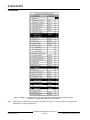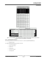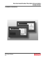
1
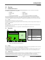
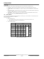
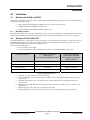
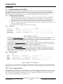
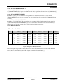
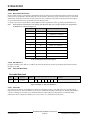
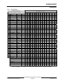
Fire Command Center/Fire Alarm Annunciators
D1256/D1257
Installation Instructions
D1256/D1257
D1256/D1257 Installation Instructions
74-06925-000-H
Page 2
© 2004 Bosch Security Systems
D1256/D1257
Contents
1.0
1.1
1.2
1.2.1
1.3
2.0
3.0
3.1
3.1.1
3.1.2
3.2
3.2.1
3.2.2
3.2.3
4.0
4.1
4.1.1
4.2
4.3
4.3.1
4.3.2
4.3.3
4.3.3.1
4.3.3.2
4.3.3.3
4.3.3.4
4.3.4
4.3.4.1
4.3.4.2
4.3.5
4.3.5.1
4.3.6
4.3.6.1
Introduction.........................................................................................................................................................................................5
Before You Begin.................................................................................................................................................................5
Type Styles Used Here .......................................................................................................................................................5
Tips, Notes, Cautions and Warnings...............................................................................................................................5
Organization and Layout.....................................................................................................................................................5
Specifications.....................................................................................................................................................................................6
Overview ...............................................................................................................................................................................................7
D1256/D1257 Features.....................................................................................................................................................7
D1256.....................................................................................................................................................................................7
D1257.....................................................................................................................................................................................7
Description.............................................................................................................................................................................7
Display.....................................................................................................................................................................................7
Audible Tones .......................................................................................................................................................................7
Switch Settings.....................................................................................................................................................................8
Installation ...........................................................................................................................................................................................9
Mounting the D1256 and D1257 ....................................................................................................................................9
Mounting Locations .............................................................................................................................................................9
Wiring the D1256 and D1257..........................................................................................................................................9
Programming the Control Panel .................................................................................................................................... 10
Command Center Assignments..................................................................................................................................... 10
Area Text.............................................................................................................................................................................. 10
Custom Function ............................................................................................................................................................... 10
CF 128 – ALARM SILENCE ?....................................................................................................................................... 10
CF 129 – TROUBLE SILENCE ? ................................................................................................................................. 11
CF 130 – DETECTOR RESET ? .................................................................................................................................. 11
CF 131 – ANUNCIATOR RESET................................................................................................................................. 11
Menu/Function List ........................................................................................................................................................... 11
Menu Item and Function .................................................................................................................................................. 12
CC Address #.................................................................................................................................................................... 12
Passcode Worksheet....................................................................................................................................................... 12
Passcode............................................................................................................................................................................. 12
User Interface ..................................................................................................................................................................... 13
Command Center Functions .......................................................................................................................................... 15
D1256/D1257 Installation Instructions
© 2004 Bosch Security Systems
Page 3
74-06925-000-H
D1256/D1257
Contents
Figures
Figure 1: D1256/D1257 Internal Arrangement............................................................................................................................7
Figure 2: Example 1 – Area Text ................................................................................................................................................... 10
Figure 3: Example 2 – Custom Function..................................................................................................................................... 10
Figure 4: Example 3 – Menu/Function List ................................................................................................................................. 11
Figure 5: Example 4 – Passcode Worksheet............................................................................................................................. 12
Figure 6: Example 5 – User Interface for D7212B1, D9112B1, and D9124 (using the D9112LTB) ........................ 13
Figure 7: Example 6 – User Interface for D7212, D7212G, D7412, D7412G, D9112, D9412, D9412G and
D9124 (using the D9112LTB-EX or D9412GLTB) ........................................................................................................ 14
Tables
Table 1: D1256/D1257 Installation Instructions Organization.................................................................................................5
Table 2: D1256/D1257 Specifications..........................................................................................................................................6
Table 3: Key to Figure 1 .....................................................................................................................................................................7
Table 4: Switch Address Settings ...................................................................................................................................................8
Table 5: Wiring Connections ............................................................................................................................................................9
Table 6: Menu/Function List Description .................................................................................................................................... 12
D1256/D1257 Installation Instructions
74-06925-000-H
Page 4
© 2004 Bosch Security Systems
D1256/D1257
Introduction
1.0
Introduction
1.1
Before You Begin
Before installing the D1256 or D1257, you should be familiar with the Operation and Installation Guide and Program
Entry Guide for the control panel you are using. When using the D1256 or D1257 with the D9112B1 Control Panel, the
firmware must be Revision 2.1 or higher.
1.2
Type Styles Used Here
We use special type styles to help you identify the objects described in this guide.
Bold text usually indicates selections that you may use while programming your control panel. It can also indicate an
important fact to be noted.
Bold Italicized text represents a prompt when used in a description.
Italicized text references you to another section of the guide, or to a different guide. We also use Italicized text to
symbolize names for records that you will create.
Courier Text shows what may be printed on the Display or internal printer.
[CAPITALIZED TEXT] in brackets represents user input (keystrokes or buttons). Capitalization may also be used for
emphasis.
1.2.1 Tips, Notes, Cautions and Warnings
Throughout this document helpful tips and notes will be presented concerning the entire application and/or
programming the unit. They will be set off as follows:
Caution
These caution the operator that physical damage to the program and/or equipment may occur.
1.3
Organization and Layout
These installation instructions consist of three chapters and an appendix. Table 1 below provides a brief description of
each section.
Chapter 1
Introduction
This is the chapter you are reading.
Chapter 2
Overview
Description of the different parts of the D1256 & D1257.
Chapter 3
Installation
Procedures on how to mount and wire the D1256 & D1257 plus procedures on programming
the control panel.
Table 1: D1256/D1257 Installation Instructions Organization
D1256/D1257 Installation Instructions
© 2004 Bosch Security Systems
Page 5
74-06925-000-H
D1256/D1257
Specifications
2.0
Specifications
Power
Nominal 12 VDC supplied by the control panel
Current Required
Idle:
104 mA
Maximum:
206 mA, with annunciator lighted and warning tone on.
Wiring
4-wire supplies Data In, Data Out, +12 VDC, and Common.
Maximum data loop resistance is 10 Ω.
Dimensions (H x W x D)
Base (HxW):
11.6 cm x 20.7 cm (4.6 in. x 8.2 in.)
Cover:
10.9 cm x 20.6 cm x 2.9 cm (4.3 in. x 8.12 in. x 0.8 in.)
Color
Fire engine red
Display
16 character vacuum fluorescent display. Each character is a 14-segment unit. Soft
blue color.
Operating Temperature
0°C to +50°C (+32°F to +122°F)
Relative Humidity
5% to 85% @ +30°C (86°F)
Table 2: D1256/D1257 Specifications
D1256/D1257 Installation Instructions
74-06925-000-H
Page 6
© 2004 Bosch Security Systems
D1256/D1257
Overview
3.0
Overview
3.1
D1256/D1257 Features
The D1256 Fire Command Center and the D1257 Fire Alarm Annunicator are 4-wire serial devices used with the
following Bosch Security Systems control panels:
D7212B1
D9112B1
•
•
•
D7212, D7212G
•
D7412, D7412G
•
D9112
•
D9412, D9412G
•
D9124 (using the D9112LTB)
•
D9124 (using the D9112LTB-EX or D9412GLTB)
Each control panel listed here supervises up to eight command centers/annunicators. You can connect a total of 32
command centers/annunicators to the system. The number of supervised command centers/annunicators, number of
areas, and the available power affect the total number of command centers/annunicators you can connect to the system.
3.1.1 D1256
The D1256 provides annunciation as well as system control.
Four function keys on the D1256 provide quick execution of alarm silencing, trouble silencing, annunciator display reset,
and sensor reset functions.
3.1.2 D1257
The D1257 provides remote annunciation without system control capability. It is well suited for use in locations where
the public may have access to it.
Two keys on the D1257 allow the user to step forward or backward through a list of system events.
3.2
Description
1
Item
1
2
3
4
5
6
2
7
7
2
2
1
3
4
2
5
2
3
4
5
Description
Vacuum florescent display
Mounting hole
Speaker for sounder
Wiring harness connector
Address DIP switches
Speaker volume control
(potentiometer)
Keypad
(arrangement is different for
D1256 and D1257)
6
Table 3: Key to Figure 1
6
Figure 1: D1256/D1257 Internal Arrangement
3.2.1 Display
Both the D1256 and D1257 use a 16-character English language display with custom programmable text. The custom text
programmed at the control panel appears in the LED display (see #1, Figure 1).
They display the latest status conditions of the fire system using words, numbers, and symbols. When an alarm occurs, it
is displayed until the user acknowledges the event at a command center. When a series of events affecting the system
occur, each event displays in order of its priority.
3.2.2 Audible Tones
Both the D1256 and D1257 have a built-in speaker that produces several distinct warning tones. The speaker volume can
be changed by adjusting the potentiometer (see Figure 1). Turn the potentiometer clockwise to increase and
counterclockwise to decrease the volume. You cannot connect external annunciation devices to the annunciators.
D1256/D1257 Installation Instructions
© 2004 Bosch Security Systems
Page 7
74-06925-000-H
D1256/D1257
Overview
The following signals are silenced by pressing the appropriate key at the D1256 Fire Command Center.
•
Fire Signal – When the system is in alarm, the annunciators emit a pulsed, high pitched "bell" tone.
•
Invalid Key Buzz – When an invalid key, or sequence of keys, is pressed, the annunciators emit a flat buzz
tone.
•
Keypad Encoding Tone – Emits a muted beep tone as each key is pressed to indicate that the entry has been
accepted. To disable this feature, see Section 3.2.3 Switch Settings.
•
Trouble Buzzer – When a trouble event occurs, such as a service alert, the annunciators emit a two tone
warble until you press the [TROUBLE SILENCE] key on the D1256.
3.2.3 Switch Settings
A 6-position switch located under the D1256 and D1257 cover allows you to select the address of each annunciator and
silence the keypad encoding tones (see Figure 1).
To access the switches:
1. Remove the front cover.
2.
a.
Using a small flat-bladed screwdriver, gently push in the two bottom tabs of the enclosure cover.
b.
While pushing the tabs in, lift the cover away from the base.
Set the switches as follows:
Switch
1
2
3
4
Address #1
ON
ON
ON
ON
Address #2
OFF
ON
ON
ON
Address #3
ON
OFF
ON
ON
Address #4
OFF
OFF
ON
ON
Address #5
ON
ON
OFF
ON
Address #6
OFF
ON
OFF
ON
Address #7
ON
OFF
OFF
ON
Address #8
OFF
OFF
OFF
ON
5
ENCODING TONE ON/OFF
Address #
6
ON
ON
ON
ON
ON
ON
ON
ON
Table 4: Switch Address Settings
D1256/D1257 Installation Instructions
74-06925-000-H
Page 8
© 2004 Bosch Security Systems
D1256/D1257
Installation
4.0
Installation
4.1
Mounting the D1256 and D1257
The D1256 and D1257 are low profile, surface-mounted units molded in durable red plastic. They can be mounted using
the following optional packages:
•
D56 Command Center Keypad Conduit Box (protected surface or flush mount)
•
D54B Command Center Flushmount Kit (brass)
•
D54C Command Center Flushmount Kit (stainless steel)
4.1.1 Mounting Locations
Do not mount annunciators in a location where they are exposed to direct sunlight. Direct sunlight can interfere with the
display screen's visibility and damage internal components. Do not mount the annunciators in wet or moist locations.
4.2
Wiring the D1256 and D1257
A four-wire flying lead (see Wiring harness connector in Figure 1) is required for the data and power connections between
the annunciators and the control panel. The annunciators come with a wiring harness consisting of four color-coded
flying leads with a female four-pin connector plug at one end.
To wire the D1256 and D1257:
1. Power down the control panel.
2. Connect the flying leads of the wiring harness (provided) to the wiring terminals on the panel.
D1256/D1257 Harness
Connecting to a compatible
control panel
(see Section 3.1 D1256/D1257 Features)
Connecting an additional
annunciator to the D9100
Carrier Module (a component
within the D9124)
12 VDC (red)
to
Terminal 32
12 VDC (Terminal 1)
Data In (yellow)
to
Terminal 31
Data Out (Terminal 3)
Data Out (green)
to
Terminal 30
Data In (Terminal 4)
COMMON (black)
to
Terminal 29
COMMON (Terminal 2)
Table 5: Wiring Connections
3.
4.
5.
6.
7.
8.
Follow the procedures in Section 3.2.3 Switch Settings.
Turn the command center over and plug in the wiring connector through the opening in the back of the
enclosure base.
Mount the annunciator's base to the wall. Secure it in place using the three mounting holes inside the
enclosure base.
Replace the cover. Align and insert the top two tabs of the enclosure cover into the top two tab slots of the
enclosure base.
Hold the top edges of the enclosure cover and base in position.
While pushing the tabs inward, press the enclosure and cover down until the cover snaps into place.
D1256/D1257 Installation Instructions
© 2004 Bosch Security Systems
Page 9
74-06925-000-H
D1256/D1257
Installation
4.3
Programming the Control Panel
The Command Center, User Interface, Command Menu (D7212B1, D9112B1, and D9124 (using the D9112LTB)) or
Function List (D7212, D7212G, D7412, D7412G, D9112, D9412, D9412G and D9124 (using the D9112LTB-EX or
D9412GLTB)), and Passcode Worksheet sections of the control panel program determine the annunciator displays and
functions available from the D1256. Key points to consider are described in the remainder of this section.
4.3.1
Command Center Assignments
1. Command Center Text. The D1256 can be used on any one of the eight addresses in the control panel.
Sections 4.3.2 through 4.3.4.2 describe programming for one D1256 assigned to Command Center #1.
2. Supervised. Certain local jurisdictions may require that fire system annunciators be supervised. If this is a
requirement in your area, set supervision to YES for the addresses that use fire alarm annunciators.
3. Scope. The D1256 is designed to acknowledge fire alarms and troubles, not burglar alarms and troubles. Set
the scope to include fire areas only.
4. Area. Program the area number of the fire area(s) as normal.
4.3.2
Area Text
Area 1
P R E
C H E
* F I
P R E
Area # is On
Area # Not Ready
Area # is Off
Area # Acct is On
S
C
R
S
S
K
E
S
A
F
S
A
L
I
Y
L
A
R
S
A
Area 2
_ _ _
_ _ _
_ _ _
_ _ _
R M
S I L
E
S Y S
T E M *
R M
S I L
_
_
_
_
_
_
_
_
_
_
_
_
_
_
_
_
_
_
_
_
_
_
_
_
_
_
_
_
_
_
_
_
_
_
_
_
_
_
_
_
_
_
_
_
_
_
_
_
_
_
_
_
Figure 2: Example 1 – Area Text
1.
2.
3.
4.
Area # is On – PRESS ALARM SIL. Fire area should remain in the OFF state at all times. If the authority level is
not programmed correctly, the fire alarm area arms and PRESS ALARM SIL displays on the fire alarm
annunciator. Pressing the [ALARM SILENCE] key will both silence any alarm(s) and disarm the area. This causes the
fire alarm annunciator to show the normal * FIRE SYSTEM * display.
Area # Not Ready – CHECK FIRE SYS. Most fire alarm areas consist of all 24-hour points and the Area # Not
Ready display is not used. If a controlled point type is used for some type of fire supervision device, and the device
becomes off-normal, CHECK FIRE SYS displays on the fire command center.
Area # is Off - * FIRE SYSTEM *. This is the normal idle text for the fire alarm annunciator.
Area # Acct is On - PRESS ALARM SIL. Fire area should remain in the OFF state at all times. If the authority
level is not programmed correctly, the fire alarm area arms and PRESS ALARM SIL displays on the fire alarm
annunciator. Pressing the [ALARM SILENCE] key silences any alarm(s) and disarms the area. This causes the fire
alarm annunciator to show the normal * FIRE SYSTEM * display.
4.3.3
Custom Function
CF 128
CF 129
CF 130
CF 131
Text
A L
T R
D E
A N
A
O
T
U
R
U
E
N
M
S I L E N C E ?
B L E
S I L E N C E ?
C T O R
R E S E T ?
C I A T O R R E S E T
1
A
A
1
2
4
4
2
5
C
7
5
6
C
_
6
0
_
_
0
0
_
_
0
E
_
_
C
_
_
_
_
_
_
_
_
_
_
_
_
_
_
_
_
_
_
_
_
_
_
_
_
_
_
_
_
_
_
_
_
_
_
_
_
Figure 3: Example 2 – Custom Function
These items must be programmed as indicated in the Custom Functions section of Command Center to make the D1256
function keys operational. The passcode 125600 has been chosen for the following examples, although any passcode may
be used.
4.3.3.1 CF 128 – ALARM SILENCE ?
Key Stroke: [1][2][5][6][0][0][E]. This custom function is programmed as the first Menu item. It is executed when the
[ALARM SILENCE] key is pressed on the D1256. The key stroke entry of 125600E is seen by the control panel as a valid
passcode entry in the area having the authority level to silence a ringing fire bell in the area. The "E" at the end of the
string represents the [ENTER] key on the command center.
D1256/D1257 Installation Instructions
74-06925-000-H
Page 10
© 2004 Bosch Security Systems
D1256/D1257
Installation
4.3.3.2 CF 129 – TROUBLE SILENCE ?
Key Stroke: [A][4][C]. This custom function is programmed as the second item in the Menu and is executed whenever
the [TROUBLE SILENCE] key is pressed on the D1256. This entry is equivalent to the execution of a [COMMAND][4]
at the D1256.
4.3.3.3 CF 130 – DETECTOR RESET ?
Key Stroke: [A][4][7]. This custom function is programmed as the third Menu item and is executed when the
[DETECTOR RESET] key is pressed on the D1256. This entry is equivalent to the execution of a [COMMAND][47] at
the D1256.
4.3.3.4 CF 131 – ANUNCIATOR RESET
Key Stroke: [1][2][5][6][0][0][C]. This custom function is programmed as the fourth command menu item and is
executed when the [ANNUNCIATOR RESET] key is pressed. Execution of this function clears the "View Memory"
buffer, but does not clear the event out of the event log contained with the control panel.
4.3.4
Menu/Function List
Menu/Function List
Menu
Item
1
2
3
4
5
6
7
8
9
10
11
Function
128
129
130
131
__9
_10
_12
_21
_29
_32
___
CC
Address 1
Yes / No
Yes / No
Yes / No
Yes / No
Yes / No
Yes / No
Yes / No
Yes / No
Yes / No
Yes / No
Yes / No
CC
Address 2
Yes / No
Yes / No
Yes / No
Yes / No
Yes / No
Yes / No
Yes / No
Yes / No
Yes / No
Yes / No
Yes / No
CC
Address 3
Yes / No
Yes / No
Yes / No
Yes / No
Yes / No
Yes / No
Yes / No
Yes / No
Yes / No
Yes / No
Yes / No
CC
Address 4
Yes / No
Yes / No
Yes / No
Yes / No
Yes / No
Yes / No
Yes / No
Yes / No
Yes / No
Yes / No
Yes / No
CC
Address 5
Yes / No
Yes / No
Yes / No
Yes / No
Yes / No
Yes / No
Yes / No
Yes / No
Yes / No
Yes / No
Yes / No
CC
Address 6
Yes / No
Yes / No
Yes / No
Yes / No
Yes / No
Yes / No
Yes / No
Yes / No
Yes / No
Yes / No
Yes / No
CC
Address 7
Yes / No
Yes / No
Yes / No
Yes / No
Yes / No
Yes / No
Yes / No
Yes / No
Yes / No
Yes / No
Yes / No
CC
Address 8
Yes / No
Yes / No
Yes / No
Yes / No
Yes / No
Yes / No
Yes / No
Yes / No
Yes / No
Yes / No
Yes / No
Figure 4: Example 3 – Menu/Function List
In the control panel’s Program Record Sheet, this section is referenced as the Menu List [for Control Panels D7212B1,
D9112B1 and D9124 (using the D9112LTB)] and as the Function List [for Control Panels D7212, D7212G, D7412,
D7412G, D9112, D9412, D9412G, and D9124 (using the D9112LTB-EX or D9412GLTB)].
D1256/D1257 Installation Instructions
© 2004 Bosch Security Systems
Page 11
74-06925-000-H
D1256/D1257
Installation
4.3.4.1 Menu Item and Function
Bosch Security Systems recommends programming the first ten menu items as indicated in Table 6. The first four menu
items must be programmed as indicated in Table 6 for the D1256 to function properly. The first four keys on the D1256
annunciator execute the first four menu items turned on at the command center address. Menu items five through ten
are optional features that can be programmed into the D1256 system.
See the Fire System User's Guide (P/N: 71-06991-000) for further explanation of these optional programmable items.
Note: Please make sure that CF 128 to 131 and any other functions that you are using in the menu are programmed
E (Enabled) not P (Passcode Required).
Menu Item
Function
Description
1
128
ALARM SILENCE?
2
129
TROUBLE SILENCE?
3
130
DETECTOR RESET?
4
131
ANUNCIATOR RESET
5
9
VIEW MEMORY?
6
10
VIEW PT STATUS?
7
12
FIRE TEST?
8
21
VIEW LOG?
9
29
REMOTE PROGRAM?
10
32
DISPLAY REV?
Table 6: Menu/Function List Description
4.3.4.2 CC Address #
Program command center addresses to YES for the first four menu items and the optionally program menu items five
through ten as YES.
4.3.5
Passcode Worksheet
Passcode Worksheet
User
Flag
000
001
User
00
01
Passcode
______
125600
User
Window
__
__
1
15
14
2
15
__
4
15
__
Area Auth
5
6
15
15
__
__
7
15
__
8
15
__
User Name
__________________________________
__________________________________
Figure 5: Example 4 – Passcode Worksheet
4.3.5.1 Passcode
A special passcode must be programmed as a valid passcode for the system to work. This passcode is used in Custom
Functions 128 and 131. Any user number can be used to establish this mandatory valid passcode. It must additionally be
created as a valid passcode in the area to which the D1256 is assigned. Bosch Security Systems recommends using
authority level 14 in conjunction with the passcode you choose (see Authority Level Selections).
D1256/D1257 Installation Instructions
74-06925-000-H
Page 12
© 2004 Bosch Security Systems
D1256/D1257
Installation
4.3.6
User Interface
Cmd Center Function
Authority Level Selections
Blank = Disabled / E = Enabled
Blank = Disabled / E = Enabled / P = Passcode
#
1
2
3
4
5
6
7
8
9
10
11
12
13
14
15
16
17
18
19
20
21
22
23
24
25
26
27
28
29
30
31
32
33
34
35
Function
Disarm
Master Arm
Mstr Arm Inst
Perim Inst
Perim Delay
Watch Mode
Perim Partial
View Area Stat
View Event Mem
View Pt Status
Walk Test
Fire Test
Send Report
Not Used
Chg Display
Chg Time/Date
Chg Passcode
Add Passcode
Del Passcode
Extend Close
View Log
Print Log
User Cmd 7
User Cmd 9
Bypass a Pt
Unbypas a Pt
Reset Sensors
Relay Control
Remote Program
Move to Area
Not Used
Display Rev
Service Walk
Default Text
Change Skeds
Force Arm
Area O/C
Restricted O/C
Perimeter O/C
Send Duress
Passcode Arm
Passcode Disarm
Command
1
2
3
4
5
6
7
8
9
10
11
12
13
14
CMD 1
CMD 11
CMD 2
CMD 3
CMD 6
CMD 8
CMD 40
CMD 44
CMD 58
CMD 41/42
CMD 49
CMD 45
CMD 55
CMD 56
CMD 53
CMD 51
CMD 7
CMD 9
CMD 0
CMD 00
CMD 47
CMD 54
CMD 43
CMD 50
CMD 59
15
E/P
P
E
E
E
E
E
E
E
E
E
E
E
E
E
E
E
E
E
E
E
E
E
E
E
E
E
E
E
E
E
E
E
E
CMD 57
CMD 52
P
P
P
P
P
P
P
E
Figure 6: Example 5 – User Interface for D7212B1, D9112B1, and D9124 (using the D9112LTB)
D1256/D1257 Installation Instructions
© 2004 Bosch Security Systems
Page 13
74-06925-000-H
D1256/D1257
Installation
Figure 7: Example 6 – User Interface for D7212, D7212G, D7412, D7412G, D9112, D9412, D9412G
and D9124 (using the D9112LTB-EX or D9412GLTB)
Note:
Please make sure that CF 128 to 131 and any other functions that you are using in the menu are programmed
E (Enabled) not P (Passcode Required).
D1256/D1257 Installation Instructions
74-06925-000-H
Page 14
© 2004 Bosch Security Systems
D1256/D1257
Installation
Figure 7 (cont’d): Example 6 – User Interface for D7212, D7212G, D7412, D7412G, D9112, D9412, D9412G
and D9124 (using the D9112LTB-EX or D9412GLTB)
4.3.6.1 Command Center Functions
The following command center function must be turned on to enable the [DETECTOR RESET] key.
• #27 Reset Sensors
It is suggested that the items below be included in the menu.
•
#9 View Event Memory
•
#10 View Point Status
•
#12 Fire Test
•
#21 View Log
•
#29 Remote Program
•
#32 Display Rev
D1256/D1257 Installation Instructions
© 2004 Bosch Security Systems
Page 15
74-06925-000-H
D1256/D1257
Installation
Further customization can be required if the D1256 is connected to a D7212B1, D9112B1, or D9124 (using
the D9112LTB) is located in an unsecured area, and/or if D1255 Command Centers are installed in the same
system. The factory loaded program for the D9124 makes these functions available without requiring a
passcode entry.
For example, the D1256 is connected to a D7212B1, D9112B1, or D9124 (using the D9112LTB) located in a
secure area, but the D1255 Command Centers are also installed, restricting command center functions by
requiring a passcode in Cmd Center Function is advisable.
Note:
For D7212B1, D9112B1, or D9124 (using the D9112LTB) Control Panels, it is important to program each of the
command center functions with an E (Enabled) and not P (Passcode Required). If any of the command center
functions are programmed with a P (Passcode Required), then that custom function must also be programmed to
execute that menu item from the command center. This custom function must include the appropriate passcode to
let the programmed function work properly. For example, if View Event Memory were to be passcode protected
and the chosen passcode was 125600, the macro string would be [A][4][0][1][2][5][6][0][0][E]. Consideration
should be given to passcode protecting the command center function in combined burglary/fire applications.
Function numbers for standard User Interface command center functions can be programmed in the Menu
Function List for D1256 and D1255 addresses. Remember to enable functions only as appropriate for the
command center at the address. As the D1256 does not have numeric keys, it can not be used to access functions
requiring a passcode.
Note:
For D7212, D7212G, D7412, D7412G, D9112, D9412, D9412G and D9124 (using the D9112LTB-EX or
D9412GLTB) Control Panels, embedding passcodes inside Custom Functions is not allowed. Therefore, any
command used in a Custom Function, should not be passcode protected.
Please make sure that CF 128 to 131 and any other functions that you are using in the menu are programmed
E (Enabled) not P (Passcode Required).
© 2004 Bosch Security Systems
130 Perinton Parkway, Fairport, NY 14450-9199 USA
Customer Service: (800) 289-0096; Technical Support: (888) 886-6189
74-06925-000-H
Installation Instructions
12/04
D1256/D1257
Page 16 of 16