1
Technical Reference Guide
Product Overview
Describes features and general specifications for the product.
Setup
Describes setup and installation of the product and peripherals.
Application Development Information
Describes how to control the printer and necessary information
when you develop applications.
Handling
Describes how to handle the product.
Replacement of the TM-H6000III
Describes precautions for replacement.
Appendix
Describes interfaces, connectors, and character code tables.
M00034100
Rev. A
Cautions
• No part of this document may be reproduced, stored in a retrieval system, or transmitted in any form
or by any means, electronic, mechanical, photocopying, recording, or otherwise, without the prior
written permission of Seiko Epson Corporation.
• The contents of this document are subject to change without notice. Please contact us for the latest
information.
• While every precaution has been taken in the preparation of this document, Seiko Epson Corporation assumes no responsibility for errors or omissions.
• Neither is any liability assumed for damages resulting from the use of the information contained
herein.
• Neither Seiko Epson Corporation nor its affiliates shall be liable to the purchaser of this product or third
parties for damages, losses, costs, or expenses incurred by the purchaser or third parties as a result of:
accident, misuse, or abuse of this product or unauthorized modifications, repairs, or alterations to this
product, or (excluding the U.S.) failure to strictly comply with Seiko Epson Corporation’s operating
and maintenance instructions.
• Seiko Epson Corporation shall not be liable against any damages or problems arising from the use of
any options or any consumable products other than those designated as Original EPSON Products or
EPSON Approved Products by Seiko Epson Corporation.
Trademarks
EPSON and ESC/POS are registered trademarks of Seiko Epson Corporation in Japan and other
countries/regions.
Microsoft and Windows are registered trademarks of Microsoft Corporation.
ESC/POS® Command System
EPSON ESC/POS is a proprietary POS printer command system that includes patented or patentpending commands. ESC/POS is compatible with all types of EPSON POS printers and displays
(excluding the TM-C100 printer).
ESC/POS is designed to reduce the processing load on the host computer in POS environments. It
comprises a set of highly functional and efficient commands and also offers the flexibility to easily make
future upgrades.
2
For Safety
Key to Symbols
The symbols in this manual are identified by their level of importance, as defined below. Read
the following carefully before handling the product.
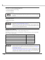
You must follow warnings carefully to avoid serious bodily injury.
WARNING
CAUTION
Provides information that must be observed to prevent damage to the equipment or loss of
data.
• Possibility of sustaining physical injuries.
• Possibility of causing physical damage.
• Possibility of causing information loss.
Provides information that must be observed to avoid damage to your equipment or a
malfunction.
Provides important information and useful tips.
3
Warnings
WARNING
4
• To avoid risk of electric shock, do not set up this product or handle cables during a
thunderstorm
• Never insert or disconnect the power plug with wet hands.
Doing so may result in severe shock.
• Handle the power cable with care.
Improper handling may lead to fire or electric shock.
∗ Do not modify or attempt to repair the cable.
∗ Do not place any heavy object on top of the cable.
∗ Avoid excessive bending, twisting, and pulling.
∗ Do not place the cable near heating equipment.
∗ Check that the plug is clean before plugging it in.
∗ Be sure to push the plug all the way in.
• Be sure to use the specified power source.
Connection to an improper power source may cause fire or shock.
• Do not place multiple loads on the power outlet.
Overloading the outlet may lead to fire.
• Shut down your equipment immediately if it produces smoke, a strange odor, or
unusual noise.
Continued use may lead to fire. Immediately unplug the equipment and contact your
dealer or a Seiko Epson service center for advice.
• Never attempt to repair this product yourself.
Improper repair work can be dangerous.
• Never disassemble or modify this product.
Tampering with this product may result in injury or fire.
• Do not allow foreign matter to fall into the equipment.
Penetration by foreign objects may lead to fire.
• If water or other liquid spills into this equipment, do not continue to use it.
Continued use may lead to fire. Unplug the power cord immediately and contact your
dealer or a Seiko Epson service center for advice.
• If you open the DIP switch cover, be sure to close the cover and tighten the screw
after adjusting the DIP switch.
Using this product with the cover open may cause fire or electric shock.
• Do not use aerosol sprayers containing flammable gas inside or around this
product.
Doing so may cause fire.
Cautions
CAUTION
• Do not connect cables in ways other than those mentioned in this manual.
Different connections may cause equipment damage or fire.
• Be sure to set this equipment on a firm, stable, horizontal surface.
The product may break or cause injury if it falls.
• Do not use this product in locations subject to high humidity or dust levels.
Excessive humidity and dust may cause equipment damage or fire.
• Do not place heavy objects on top of this product. Never stand or lean on this
product.
Equipment may fall or collapse, causing breakage and possible injury.
• Take care not to injure your fingers on the manual cutter:
∗ When you remove printed paper.
∗ When you perform other operations, such as loading/replacing roll paper.
• Do not open the roll paper cover without taking the necessary precautions, as this
can result in injury from the autocutter fixed blade.
• To ensure safety, unplug this product before leaving it unused for an extended
period.
Restriction of Use
When this product is used for applications requiring high reliability/safety, such as
transportation devices related to aviation, rail, marine, automotive; disaster prevention devices;
various safety devices; or functional/precision devices, etc., you should use this product only
after giving consideration to including fail-safes and redundancies into your design to maintain
safety and total system reliability. Because this product was not intended for use in applications
requiring extremely high reliability/safety, such as aerospace equipment, main communication
equipment, nuclear power control equipment, or medical equipment related to direct medical
care, etc., please make your own judgement on this product's suitability after a full evaluation.
5
About this Manual
Aim of the Manual
This manual was created to provide information on the development, design, and installation of
POS systems and the development and design of printer applications for developers.
Manual Content
The manual is made up of the following sections:
Chapter 1
Product Overview
Chapter 2
Setup
Chapter 3
Application Development Information
Chapter 4
Handling
Chapter 5
Replacement of the TM-H6000III
Appendix
Specifications of Interfaces and Connectors
Character Code Tables
6
Contents
■ For Safety...............................................................................................................................3
Key to Symbols ....................................................................................................................................... 3
Warnings ................................................................................................................................................. 4
Cautions.................................................................................................................................................. 5
■ Restriction of Use ..................................................................................................................5
■ About this Manual ................................................................................................................6
Aim of the Manual................................................................................................................................. 6
Manual Content .................................................................................................................................... 6
Product Overview ........................................................................11
■ Features ...............................................................................................................................11
■ Product Configurations ......................................................................................................13
Interfaces .............................................................................................................................................. 13
Colors .................................................................................................................................................... 13
Accessories........................................................................................................................................... 14
■ Part Names and Functions.................................................................................................15
Power Switch ........................................................................................................................................ 15
Power Switch Cover............................................................................................................................. 15
Control Panel ....................................................................................................................................... 16
Offline .................................................................................................................................................... 17
Connectors........................................................................................................................................... 18
■ Error Status ...........................................................................................................................19
Automatically Recoverable Errors ..................................................................................................... 19
Recoverable Errors............................................................................................................................... 19
Unrecoverable Errors ........................................................................................................................... 20
■ NV Memory (Non-Volatile Memory) ................................................................................22
NV Graphics Memory.......................................................................................................................... 22
User NV Memory .................................................................................................................................. 22
Memory Switches................................................................................................................................. 23
R/E (Receipt Enhancement) .............................................................................................................. 23
User-defined Page ............................................................................................................................... 23
Maintenance Counter ........................................................................................................................ 23
■ Product Specifications .......................................................................................................24
Printing Specifications ......................................................................................................................... 25
Character Specifications .................................................................................................................... 27
Paper Specifications............................................................................................................................ 28
Printable Area ...................................................................................................................................... 31
Printing and Cutting Positions ............................................................................................................. 34
Ribbon Cassette .................................................................................................................................. 34
MICR Reader (Factory-Installed Option) .......................................................................................... 35
Electrical Characteristics .................................................................................................................... 36
7
Reliability ...............................................................................................................................................37
Environmental Conditions ...................................................................................................................38
External Dimensions and Mass............................................................................................................39
■ Option Specifications ........................................................................................................ 40
Power Supply Unit (PS-180) ..................................................................................................................40
Setup .............................................................................................41
■ Flow of Setup....................................................................................................................... 41
■ Installing the Printer............................................................................................................ 42
Important Notes ...................................................................................................................................42
■ Adjusting the Paper Roll Near-End (NE) Sensor............................................................... 43
■ Changing the Paper Width................................................................................................ 44
■ Setting the DIP Switches..................................................................................................... 45
Setting Procedure.................................................................................................................................45
For Serial Interface................................................................................................................................46
For Parallel Interface ............................................................................................................................48
For Built-in USB Interface ......................................................................................................................49
For Ethernet/Wireless LAN Interface ...................................................................................................50
Selecting the Print Density (DIP Switches 2-3/2-4)............................................................................. 51
Selecting the BUSY Status ....................................................................................................................52
■ Connecting the Printer to the Host Computer ................................................................. 53
For Serial Interface................................................................................................................................53
For Parallel Interface ............................................................................................................................56
For USB Interface...................................................................................................................................57
For Ethernet Interface ..........................................................................................................................59
For Wireless LAN Interface ...................................................................................................................61
■ Connecting the Power Supply Unit (PS-180) .................................................................... 62
Connecting the Power Supply Unit ....................................................................................................62
■ Attaching the Connector Cover ....................................................................................... 64
■ Setting the Memory Switches/Receipt Enhancement.................................................... 65
Functions ...............................................................................................................................................66
■ Connecting the Cash Drawer ........................................................................................... 71
Connecting the Drawer Kick-out Cable............................................................................................71
Application Development Information......................................73
■ How to Control the Printer.................................................................................................. 73
Selecting a Driver .................................................................................................................................73
ESC/POS Commands ...........................................................................................................................74
8
■ Software and Manuals .......................................................................................................83
How to Get Drivers, Manuals, and the Utility .................................................................................... 83
Printer Drivers........................................................................................................................................ 83
Utilities.................................................................................................................................................... 85
■ Setting/Checking Modes...................................................................................................86
Self-test Mode ...................................................................................................................................... 86
Hexadecimal Dumping Mode ........................................................................................................... 89
NV Graphics Print Mode ..................................................................................................................... 90
Receipt Enhancement Information Print Mode............................................................................... 92
Memory Switch Setting Mode............................................................................................................ 93
Handling .......................................................................................95
■ Usage Precautions..............................................................................................................95
■ Installing and Replacing the Ribbon Cartridge ...............................................................95
Installing and Replacing the Ribbon Cartridge for E/P ................................................................... 97
■ Installing and Replacing Paper.........................................................................................99
Inserting Slip Paper .............................................................................................................................. 99
Inserting Validation Paper (For Validation Models)........................................................................ 101
Installing and Replacing Roll Paper................................................................................................. 102
■ Removing Jammed Paper...............................................................................................104
Removing Jammed Slip Paper......................................................................................................... 104
Removing Jammed Roll Paper ........................................................................................................ 105
■ Cleaning the Printer..........................................................................................................106
Cleaning the Printer Case ................................................................................................................ 106
Cleaning the Thermal Head............................................................................................................. 106
Cleaning the MICR Head (For Models with the MICR Reader).................................................... 107
■ Preparing for Transport .....................................................................................................108
Replacement of the TM-H6000III ..............................................109
■ Compatibility ....................................................................................................................109
Printing ................................................................................................................................................ 109
Number of Head Energizing Parts for Receipt Printing .................................................................. 109
Printable Area .................................................................................................................................... 109
Cutting Method ................................................................................................................................. 109
Receive Buffer .................................................................................................................................... 110
Memory Capacity ............................................................................................................................. 110
Electrical Characteristics .................................................................................................................. 110
DIP Switches ....................................................................................................................................... 110
Printer Status ....................................................................................................................................... 110
Logo Registration ............................................................................................................................... 110
Driver Compatibility........................................................................................................................... 111
9
Two-Color Printing...............................................................................................................................111
Ink Ribbon Cartridge..........................................................................................................................111
Overall Dimensions .............................................................................................................................112
■ Additional Functions and Functional Improvements.................................................... 113
Print Speed ..........................................................................................................................................113
Receipt Print Density ..........................................................................................................................113
Slip Paper.............................................................................................................................................114
Bar codes ............................................................................................................................................114
Tone......................................................................................................................................................114
Interface ..............................................................................................................................................114
Connection of Customer Display .....................................................................................................115
Customized Value ..............................................................................................................................115
R/E Information Printing Mode ..........................................................................................................115
Memory Switch Setting Mode ..........................................................................................................116
Maintenance Counter.......................................................................................................................116
Power Supply Unit Capacity .............................................................................................................116
USB Low Power Consumption Mode ................................................................................................116
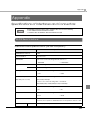
Appendix ....................................................................................117
■ Specifications of Interfaces and Connectors................................................................ 117
RS-232 Serial Interface........................................................................................................................117
IEEE 1284 Parallel Interface................................................................................................................120
USB (Universal Serial Bus) Interface ...................................................................................................123
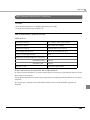
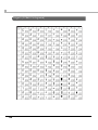
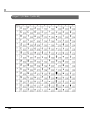
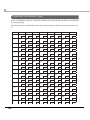
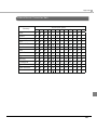
■ Character Code Tables ................................................................................................... 124
Common to All Pages........................................................................................................................124
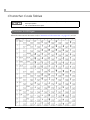
Page 0 [PC437: USA, Standard Europe]...........................................................................................125
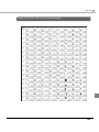
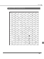
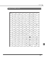
Page 1 (Katakana).............................................................................................................................126
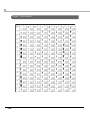
Page 2 (PC850: Multilingual) .............................................................................................................127
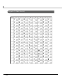
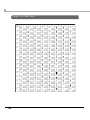
Page 3 (PC860: Portuguese) .............................................................................................................128
Page 4 (PC863: Canadian-French)..................................................................................................129
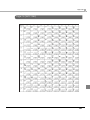
Page 5 (PC865: Nordic) .....................................................................................................................130
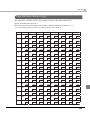
Page 16 (WPC1252) ...........................................................................................................................131
Page 17 (PC866: Cyrillic #2) ..............................................................................................................132
Page 18 (PC852: Latin2) ....................................................................................................................133
Page 19 (PC858: Euro) .......................................................................................................................134
Page 254 (User-Defined Page)..........................................................................................................135
Page 255 (User-Defined Page)..........................................................................................................136
International Character Sets.............................................................................................................137
10
Chapter 1 Product Overview
Product Overview
This chapter describes features and specifications of the product.
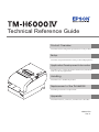
Features
The TM-H6000IV is a high-end POS printer that can print on both slip paper (checks) and roll
paper (receipts).
The features are as follows:
1
Slip printing
• An optional Magnetic Ink Character Recognition (MICR) reader and an optional endorsement
printer (E/P) enable the printer to perform consecutive reading of MICR characters,
endorsement printing, and front printing, in a single pass of a check.
• High throughput using bidirectional minimum distance printing.
• A mechanical form stopper gives stability to slip paper.
• Opening the front carriage unit makes removing jammed paper easy.
• The validation model printer can print an 8-line validation.
Receipt printing
• High-speed printing enables issuing of batch receipts.
• Graphics are also printed with high-speed printing.
• Multi-tone graphics printing is possible.
• Bar code and two-dimensional symbol printing is possible.
• Easy drop-in paper loading.
• An autocutter is standard equipment.
• Paper-saving function is supported.
Software
• Command protocol is based on the ESC/POS Proprietary Command System.
• OPOS ADK, JavaPOS ADK, and Windows printer drivers are available.
• Automatic Status Back (ASB) function that automatically transmits changes in the printer
status is supported.
• A maintenance counter function is supported.
11
Interfaces
• Various interface boards (EPSON UB series) can be used.
• A built-in USB interface is also available for serial/parallel interface models.
Environment
ENERGY STAR qualified. (Some configurations may be exempted, depending on their
components.)
Others
• Small footprint and simple design.
• Direct connection of EPSON customer display series (DM-D) is possible.
12
Chapter 1 Product Overview
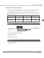
Product Configurations
There are two models of the TM-H6000IV: a standard model that can perform slip printing and
receipt printing and a validation model that can also perform validation printing.
An optional MICR reader that can read magnetic ink characters is available for both of the
models. Also, an endorsement printer (E/P) that can print on the back of checks is available for
the standard model.
Validation
MICR reader
E/P
Standard models
Not equipped
Equipped/
Not equipped
Equipped/
Not equipped
Validation models
Equipped
Equipped/
Not equipped
Not equipped
1
Interfaces
Built-in USB interface
Interface board (UB):
Serial/Parallel/USB/
Ethernet/Wireless LAN
㩷
(Only for serial/parallel
interface models)
• Serial UB + built-in USB interface model
• Parallel UB + built-in USB interface model
• USB interface model
• Ethernet interface model
• Wireless LAN interface model
Colors
• ECW (Epson Cool White)
• EDG (Epson Dark Gray)
13
Accessories
Included
• Thermal roll paper (for operation check)
• Ink ribbon cartridge (Model: ERC-32, ERC-43*1)
• Power switch cover
• Connector cover
• User’s manual
• Warranty certificate*2
*1: Only for the model with the endorsement printer.
*2: May not be included, depending on the model.
Options
• AC adapter (Model: PS-180)
• AC cable (Model: AC-170)
• Interface boards (UB series)
• EPSON customer display series (DM-D)
• Paper guide for 58 mm width paper (Model: PG-58II)
For Engergy Star-compatible models, use only the AC adapter that came with the printer.
14
Chapter 1 Product Overview
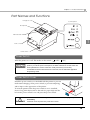
Part Names and Functions
Roll paper cover
Control panel
Receipt unit
Manual cutter
1
Front cover
Power switch
Power Switch
Turns the printer on or off. The marks on the switch: (
: OFF/
: ON)
Before turning the printer off, it is recommended that you send a power-off command to the
printer. If you use the power-off sequence, the latest maintenance counter values are
saved. (Maintenance counter values are usually saved every two minutes.)
For detailed information about ESC/POS commands, see the ESC/POS Application
Programming Guide.
Power Switch Cover
Install the power switch cover included with the printer to prevent
inadvertent changing of the power switch, to prevent tampering,
and to improve the appearance of the printer.
To reset the printer when the power switch cover is installed,
insert a long, thin object (such as the end of a paper clip) into the
hole in the power switch cover and press the power switch.
WARNING
If an accident occurs with the power switch cover attached, unplug the power cord
immediately.
Continued use of the printer may cause fire or shock.
15
Control Panel
(Power) LED
Error LED
Paper LED
Slip LED
Feed button
Release button
Power LED (Green)
• Lights when the power supply is on.
• Goes out when the power supply is turned off.
Error LED (Orange)
Lights or flashes when the printer is offline.
• Lights after the power is turned on or after a reset (offline). Automatically goes out when the
printer is ready.
• Lights when the end of the roll paper is detected and printing has stopped (offline). If this
happens, replace the roll paper.
• Flashes when an error occurs. (For details about the flash codes, see "Error Status" on page 19.)
• Goes out during regular operation (online).
Paper LED (Orange)
• Lights when roll paper is running low or is out.
• Off when there is a sufficient amount of roll paper remaining.
• Flashes when a self-test is in progress or during a macro execution standby state.
Slip LED (Green)
• Lights during printing on slip paper.
• Flashes during slip insertion waiting and slip removal waiting.
• Goes out 2 seconds after slip removal.
16
Chapter 1 Product Overview
Feed button
Pressing this button once feeds paper by one line. Holding this button down feeds paper
continuously.
Release button
Pressing this button releases inserted slip paper.
Enabling/disabling of the Feed and Release buttons can be selected by a command. If the
command is set to disable these buttons, they do not function.
Offline
1
The printer automatically goes offline under the following conditions:
• During power on (including resetting with the interface) until the printer is ready
• During the self-test
• While roll paper is fed using the Feed button
• When the printer stops printing due to a paper-end (if an empty paper supply is detected by
the roll paper end sensor or if the driver has been set to stop printing when a roll paper nearend is detected)
• During a macro execution standby state
• When a temporary abnormality occurs in the power supply voltage
• When an error has occurred
17
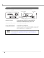
Connectors
All cables are connected to the connector panel on the lower rear of the printer.
Interface
Customer display
Power supply
Ethernet
Serial
Parallel
Drawer kick-out
• Interface connector:
USB interface
Connects the printer with the host computer interface.
The interface type differs depending on the model.
• Customer display connector: Connects the customer display (DM-D series).
• Drawer kick-out connector:
Connects the cash drawer.
• Power supply connector:
Connects the power supply unit.
• USB interface connector:
Connects the printer with the host computer via the USB
interface. Only the serial/parallel interface models have this
built-in USB interface as a standard feature.
For details on how to connect the interface connector, power supply connector, and drawer
kick-out connector, see "Connecting the Printer to the Host Computer" on page 53,
"Connecting the Power Supply Unit (PS-180)" on page 62, and "Connecting the Cash
Drawer" on page 71.
18
Chapter 1 Product Overview
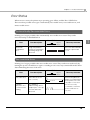
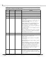
Error Status
When an error occurs, the printer stops operating, goes offline, and the Error LED flashes.
There are three possible error types: automatically recoverable errors, recoverable errors, and
unrecoverable errors.
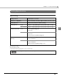
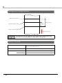
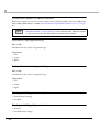
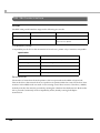
Automatically Recoverable Errors
Printing is no longer possible when automatically recoverable errors occur. They can be
recovered easily, as described below.
Error LED flash code
Error
Print head
temperature
error
Error description
Approx.
320 ms
A high temperature
outside the head drive
operating range was
detected.
Recovery measure
Recovers automatically
when the print head
cools.
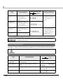
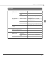
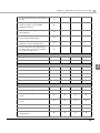
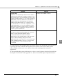
Recoverable Errors
Printing is no longer possible when recoverable errors occur. They can be recovered easily by
turning the power off and then on again or sending an error recovery command from the driver
after eliminating the cause of the error.
Error LED flash code
Error
Autocutter error
Error description
Approx.
320 ms
Autocutter does not
work correctly.
5,120 ms
Carriage
detection error
in endorsement
printing
The carriage is
malfunctioning due to
a paper jam, or the slip
removal cannot be
detected.
Recovery measure
Remove the jammed
paper or foreign matter
in the printer, close the
roll paper cover, send
the error recovery
command, or turn the
power off and on to
recover.
19
1
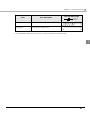
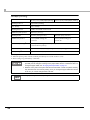
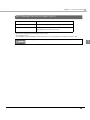
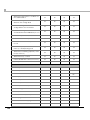
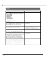
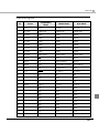
Error LED flash code
Error
Error description
Slip ejection
error
The slip is not ejected
after feeding a
specified amount of
paper.
Mechanical
operation error
The position of the
platen/roller open and
close mechanism
cannot be detected.
Roll paper cover
open error
The roll paper cover
was opened during
printing.
Receipt unit
open error*
The receipt unit was
opened during printing.
Approx.
320 ms
Recovery measure
Send the error recovery
command or turn the
power off and on to
recover.
Close the roll paper
cover, and then send
the error recovery
command or turn the
power off and on to
recover.
*: Occurs only when memory switch 8-8 is set to ON.
The error recovery command is valid only if a recoverable error (excluding automatically
recoverable errors) occurs.
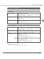
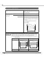
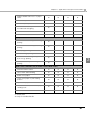
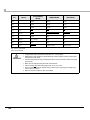
Unrecoverable Errors
Printing is no longer possible when unrecoverable errors occur. The printer must be repaired.
Turn off the power immediately when unrecoverable errors occur.
CAUTION
Error LED flash code
Error
20
Error description
R/W error in memory
or gate array
After R/W checking, the printer does not
work correctly.
High voltage error
The power supply voltage is extremely
high.
Low voltage error
The power supply voltage is extremely low.
CPU execution error
The CPU is executing an incorrect address.
Approx.
320 ms
Chapter 1 Product Overview
Error LED flash code
Error
Error description
Interface board error*
The interface board is not connected.
Circuit error
A circuit error is detected.
Approx.
320 ms
*: This error occurs when the interface board is not connected, DIP switch 2-2 is set to On, and the interface mode
is set to UB/built-in USB automatic selection or fixed to UB with the customized value.
1
21
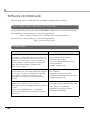
NV Memory (Non-Volatile Memory)
The printer's NV memory stores data even after the printer power is turned off. NV memory
contains the following memory areas for the user:
• NV graphics memory
• User NV memory
• Memory switches
• Receipt Enhancement (R/E)
• User-defined page
• Maintenance counter
As a guide when you program applications, NV memory should be rewritten 10 or fewer
times a day.
NV Graphics Memory
Graphics, such as shop logos to be printed on receipts, can be stored. Even with a serial interface
model whose communication speed is low, high speed graphic printing is possible.
Use the TM-H6000IV Utility to register graphics. You can also print and confirm the registered
graphics in the TM-H6000IV Utility or NV graphics memory print mode.
• For detailed information about the TM-H6000IV Utility, see the TM-H6000IV Utility User’s
Manual.
• For information about how to use the NV graphics memory print mode, see "NV
Graphics Print Mode" on page 90.
User NV Memory
You can store and read text data for multiple purposes, such as for storing a note including
customizing or maintenance information of the printer.
Use ESC/POS commands to store and read the text data.
For information about ESC/POS commands, see the ESC/POS Application Programming
Guide.
22
Chapter 1 Product Overview
Memory Switches
With the memory switches, which are software switches for the printer, you can configure
various settings of the printer.
For information about the memory switches see "Setting the Memory Switches/Receipt
Enhancement" on page 65.
R/E (Receipt Enhancement)
Graphics, such as shop logos, can be printed on top or bottom of receipts by setting R/E.
For information about R/E, see "Setting the Memory Switches/Receipt Enhancement" on page
65.
User-defined Page
You can store character data in the user-defined page (character code table: pages 254 and 255) so
that you can also print characters not resident in the printer.
Maintenance Counter
With this function, printer information, such as the number of lines printed, the number of MICR
readings, the number of autocuts, and printer operation time after the printer starts working, is
automatically stored in NV memory. You can read or reset the information with the TM-H6000IV
Utility, the Status API of the APD, or OPOS ADK to use it for periodical checks or part
replacement.
23
1
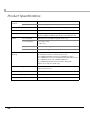
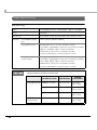
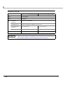
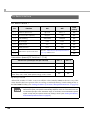
Product Specifications
Printing
method
Receipt
Thermal line printing
Slip/Endorsement
9-pin serial impact dot matrix
Cutting method
Partial cut (cutting with one point in left edge left uncut)
MICR reader (factory option)
Magnetic bias
Interfaces
Serial (RS-232), Parallel (IEEE 1284),USB (2.0 Full-speed),
Ethernet (10BASE-T/100BASE-TX), Wireless LAN (IEEE 802.11b)
Buffers
Receive buffer
4 KB/45 bytes (selectable using DIP switch 1-2)
Download buffer
For receipt: 12 KB
For slip: 3 KB
NV graphics data
384 KB (initial setting)
User NV memory
1 KB (initial setting)
Bar code/two-dimensional symbol
printing
UPC-A, UPC-E, JAN 8 (EAN 8), JAN 13 (EAN 13), CODE 39,
ITF, CODABAR, CODE 93, CODE 128, GS1-128,
GS1 DataBar Omnidirectional, GS1 DataBar Truncated,
GS1 DataBar Stacked, GS1 DataBar Stacked Omnidirectional,
GS1 DataBar Limited, GS1 DataBar Expanded,
GS1 DataBar Expanded Stacked, PDF417, QR CODE,
MaxiCode, Composite Symbology
Ink ribbon cartridge
Slip: ERC-32
Endorsement: ERC-43
Supplied voltage
DC 24 V ± 7%
Overall dimensions (H × W × D)
181 × 160 × 278 mm {7.13 × 6.30 × 10.94"}
Weight (mass)*
Approx. 4.0 kg {8.82 lb}
*: For the standard model (with MICR reader and E/P)
24
Chapter 1 Product Overview
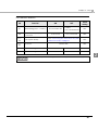
Printing Specifications
Slip printing
Printing method
Serial impact dot matrix
Head wire configuration
9-pin vertical line, wire pitch approximately 0.353 mm {1/72"}
Printing direction
Bidirectional, minimum distance printing
Printing speed*
Characters per line
Front
Approx. 5.7 lps (printing 40 columns per line with 17.8 cpi)
Endorsement
Approx. 4.0 lps (printing 40 columns per line with 21.2 cpi)
Front
Font A (initial setting): 45
1
Font B: 60
Endorsement
Font A: 25
Font B: 33
Endorsement font (initial setting): 40
Character dot
spacing
Front
Font A (initial setting): 1 dot
Font B: 2 half dots
Endorsement
Font A: 1 dot
Font B: 2 half dots
Endorsement font (initial setting): 1 dot
lps: lines per second
cpi: characters per inch
*: when the head energizing time is set to normal mode.
Printing speed may be slower, depending on such items as the data transmission speed.
25
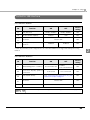
Receipt printing
80 mm {3.15"} width paper printing
58 mm {2.28"} width paper printing
Printing method
Thermal line printing
Dot density
180 × 180 dpi
Printing direction
Unidirectional with friction feed
Maximum print speed*1
300 mm/s {11.81"/s}
Printing width
72.0 mm (2.83"), 512 dots
50.8 mm (2.0"), 360 dots
Characters per line
Font A (initial setting): 42
Font A (initial setting): 30
Font B: 56
Font B: 40
Character spacing*2
Font A (initial setting): 0.28 mm (2 dots)
Font B: 0.28 mm (2 dots)
Paper feed speed
Approx. 200 mm/s {7.87"/s} (during continuous printing)
Line spacing*2
Approx. 4.23 mm {1/6"}
dpi: dots per inch
*1: When the printer prints with the standard print density level at 24V and 25°C {77°F}.
*2: Initial setting. Programmable by commands.
• When changing the paper width, you need to install the optional 58 mm paper guide
(PG-58II) and to change the setting for the paper width with the customized value. To
change the paper width, see "Changing the Paper Width" on page 44.
• Because some parts of the print head and the autocutter contact the platen and they
may become worn out in 58 mm printing, once you change the paper width from 80 mm
to 58 mm, you cannot change it back to 80 mm.
Printing speed may be slower, depending on such items as the data transmission speed.
26
Chapter 1 Product Overview
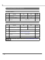
Character Specifications
Slip printing
Number of characters
Alphanumeric characters: 95
Extended graphics: 128 × 12 pages (including user-defined page)
International characters: 37 character types
Character structure
Font A: 5 × 9
Font B: 7 × 9
Endorsement font: 5 × 7
Character size
1
Font A: 1.56 × 3.11 mm
Font B: 1.24 × 3.11 mm
Endorsement font: 1.09 × 2.41 mm
Receipt printing
Number of characters
Alphanumeric characters: 95
Extended graphics: 128 × 11 pages (including user-defined page)
International characters: 37 character types
Character structure
Font A: 12 × 24 (including 2-dot horizontal spacing)
Font B: 9 × 17 (including 2-dot horizontal spacing)
Character size
Font A
Standard: 1.41 × 3.39 mm
Double-height: 1.41 × 6.77 mm
Double-width: 2.82 × 3.39 mm
Double-width, double-height: 2.82 × 6.77 mm
Font B
Standard: 0.99 × 2.40 mm
Double-height: 0.99 × 4.80 mm
Double-width: 1.98 × 2.40 mm
Double-width, double-height: 1.98 × 4.80 mm
Note:
1. Space between characters is not included.
2. Characters can be scaled up to 64 times as large as the standard size.
27
Paper Specifications
Slip printing
Types
Normal paper, pressure sensitive paper, carbon copy paper
Form
Cut sheet
Size (W × L)
68 to 230 mm × 68 to 297 mm {2.68 to 9.06" × 2.68 to 11.69"}
Thickness
Normal paper (singleply)
0.09 to 0.22 mm {0.0035 to 0.0087"}
Copy paper (front)
Backing paper: 0.07 to 0.12 mm {0.0028 to 0.0047"}
Copy paper, original paper: 0.04 to 0.07 mm {0.0016 to 0.0028"}
Carbon copy paper: Approx. 0.035 mm {0.0014"}
Total thickness: 0.09 to 0.47 mm {0.0035 to 0.0185"}
However, total number of sheets must be 4 or fewer.
Copy paper
(endorsement)
Backing paper: 0.07 to 0.12 mm {0.0028 to 0.0047"}
Copy paper, original paper: 0.04 to 0.07 mm {0.0016 to 0.0028"}
Copy carbon paper: Approx. 0.035 mm {0.0014"}
Total thickness: 0.09 to 0.31 mm {0.0035 to 0.0122"}
However, total number of sheets must be 3 or fewer.
• Copy capability is greatly influenced by the ambient temperature, so printing must be
performed under the conditions described below.
Copy paper (front)
Copy paper
(endorsement)
28
Ambient
temperature
Number of copies
Total thickness
Original + 3 copies
0.31 mm or less
10 to 40°C
{50 to 104°F}
Original + 2 copies
0.31 mm or less
5 to 45°C
{41 to 113°F}
Original + 2 copies
0.47 mm or less
10 to 40°C
{50 to 104°F}
Original + 2 copies
0.31 mm or less
10 to 40°C
{50 to 104°F}
Chapter 1 Product Overview
• The slip paper must be flat, without curls or wrinkles, especially at the top edges.
• When using slip paper with a glued area, choose it carefully, since paper feeding is
affected by gluing conditions, such as position and dimension.
OK to use
Use carefully
Use carefully
Use carefully
Glued area
Paper inserting direction
• Use thinner paper (N30 or equivalent) between the top and bottom sheets of multi-ply
paper. If thick paper is used, the copy capability is lowered.
• Do not use paper that has holes, or is translucent at the BOF sensor position.
• Do not use paper that has holes or dark positions with low reflection (less than 40%
reflection) on the front at the TOF sensor position.
40
20
10
Pa p e r i n s e r t i n g
direction
Area where holes are
prohibited and reflection
rate on the front should be
40% or more.
[units: mm (All the numeric values are typical.)]
• Do not use paper that has holes or dark positions with low reflection (less than 40%
reflection) on the back at the validation sensor (only for the validation models).
7
Pa p e r i n s e r t i n g
direction
20
Area where holes are
prohibited and reflection
rate on the front should be
40% or more.
[units: mm (All the numeric values are typical.)]
29
1
Receipt printing
80 mm {3.15"} width paper printing
Type
Thermal paper
Form
Roll paper
Size
58 mm {2.28"} width paper printing
Roll paper
diameter
83 mm {3.27"} maximum
Roll paper spool
Inside: 12 mm {0.47"}, Outside: 18 mm {0.71"}
Roll width when
taken up
80 + 0.5/-1.0 mm
58 + 0.5/-1.0 mm
Paper width
79.5 ± 0.5 mm
57.5 ± 0.5 mm
NTP080-80
NTP058-80
Specified roll paper type
• Paper must not be pasted to the roll paper spool.
• For the best print quality for each paper type, it is recommended to test the print density.
(See "Setting the Memory Switches/Receipt Enhancement" on page 65.)
30
Chapter 1 Product Overview
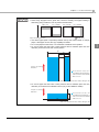
Printable Area
5
Slip (front) printing
Top margin
5.6
85.4
1
When a model without E/P
performs back feeding after
front printing completed.
18.4
57.15
40.0
When a model with E/P performs
back feeding after front printing
completed.
When the printer ejects paper
after front printing completed.
[units: mm (All the numeric values are typical.)]
6.9
Slip (endorsement) printing
Top margin
22.0
47.8
Bottom margin
16.2
Paper feeding
direction
[units: mm (All the numeric values are typical.)]
31
Slip (validation) printing
5.6
18.4
32.8
85.4
Bottom margin
[units: mm (All the numeric values are typical.)]
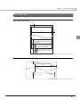
Receipt printing (80 mm paper width)
79.5 ± 0.5
3.7 ± 2.0
72.2*
[units: mm (*: typical)]
• In 2-divided energizing, the print position within the printable area of the thermal
elements for dots 1 to 256 and 257 to 512 is shifted approximately 0.07 mm {0.0028"} as
shown in the figure below.
25
Approx. 0.07 mm
51
25
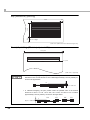
• In 4-divided energizing, the print position within the printable area of the thermal
elements for dots 1 to 128, 129 to 256, 257 to 384, and 385 to 512 is shifted
approximately 0.04 mm {0.0016"} as shown in the figure below.
Approx. 0.04 mm
32
Chapter 1 Product Overview
Receipt printing (58 mm paper width)
57.5 ± 0.5
50.8*
3.1 ± 2.0
1
[units: mm (*: typical)]
33
Printing and Cutting Positions
Manual-cutter position
Approx. 24 mm
Approx.
10 mm
Autocutter blade position
Center of the print dotline
Paper feed direction
The values above may vary slightly as a result of paper slack or variations in the paper.
Take this into account when setting the cutting position of the autocutter.
Ribbon Cassette
Model
Slip printing (front): ERC-32
Endorsement printing: ERC-43
Color
Life*
Black
ERC-32
4,000,000 characters
ERC-43
3,000,000 characters
*: at 25°C {77°F} with continuous printing
34
Chapter 1 Product Overview
MICR Reader (Factory-Installed Option)
Reading method
Magnetic bias
Supported fonts
E13B, CMC7 (Alphabets are not supported.)
Recognition rate*
Recognition rate: 99% or more
Recognition error rate: 0.1% or less
*: When using ANSI/ISO specified paper at 25°C {77°F}
Recognition rate (%)=
{Total number of checks-(number of checks misread or not recognized)}/Total number of checks × 100
For reading MICR characters, paper length must be 120 mm {4.72"} or more.
1
35
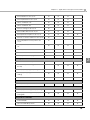
Electrical Characteristics
Supply voltage
DC 24V ± 7%
Ripple voltage: 300 mVpp or less (for models
with MICR reader)
Current consumption
Standby
(when using the PS180 at 24V)
Operating
Mean: Approximately 0.1 A
Slip printing
Mean: Approximately 1.7 A
Receipt printing
Mean: Approximately 1.8 A
Note: When print ratio is approximately 18%
• Continuous printing for 50 lines (repeating
20H-7FH)
∗ Font A, 42 columns, ASCII character
• 5 line feeding
• Autocutting
#$%&'
$%&'
42 columns
If printing is continuously performed with a high ratio, the overcurrent protection may be
activated and result in uneven print density or a low voltage error. Therefore, the printing
length must not exceed the following values when printing with high print ratio.
Print ratio: Number of dots being energized per one dot line/Total number of dots per one
dot line (512 dots)
Print ratio
80%
100%
Print example
72 mm
58 mm
Print length
36
30 mm
20 mm
Chapter 1 Product Overview
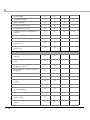
Reliability
Life
Slip printer section/
Endorsement
printer section
Receipt printer
section
MTBF
MCBF
Number of carriage
driving times
1,200,000 times for each section
Number of paper
feeds
Total for the sections: 27,000,000 lines
Print head
200 million characters (when printing with Font B only)
Printer mechanism
20,000,000 lines (when repeatedly
printing 10 lines with 4.23 mm line spacing
and feeding 5 lines)
Print head
150 million pulses, 150 km
Autocutter
2,000,000 cuts (when using the specified
original paper types, PD150R or PD160R)
MICR reader mechanism (factory-installed
option)
240,000 passes (for US personal checks)
Slip printer section/
Endorsement printer section
180,000 hours
Receipt printer section
360,000 hours
Slip printer section/
Endorsement
printer section
Receipt printer section
Number of carriage
driving times
29,000,000 times for each section
Number of paper
feeds
Total for the sections: 65,000,000 lines
96,000,000 lines
37
1
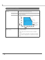
Environmental Conditions
Temperature/
Humidity
Operating
5 to 45°C {41 to 113°F}, 10 to 90% RH (See the operating
temperature and humidity range below.)
Storage
-10 to 50°C {14 to 122°F}, 10 to 90% RH (except for paper and
ink ribbon cartridges)
[%RH]
34°C, 90%
4GNCVKXG*WOKFKV[
90
80
40°C, 65%
60
1RGTCVKPIGPXKTQPOGPV
TCPIG
40
45°C, 50%
Specified original paper:
P300, P310, P350
20
Specified original paper
other than above
10
0
Acoustic noise (operating, receipt
printer section)
0
10
20
30
40
50
#ODKGPVVGORGTCVWTG=͠?
Approximately 55 dB (bystander position) (including
autocutting operation)
Note:
The values above are measured in the Epson evaluation
condition.
Acoustic noise differs depending on the paper used, printing
contents, and the setting values, such as print speed or print
density.
38
Chapter 1 Product Overview
External Dimensions and Mass
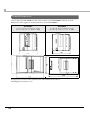
The external dimensions and mass of the standard model (with MICR reader and E/P)
• Height: Approximately 181 mm {7.13"}
• Width: Approximately 160 mm {6.30"}
• Depth: Approximately 278 mm {10.94"} (excluding the connector cover)
• Mass: Approximately 4.0 kg {8.82 lb}
1
39
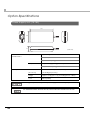
Option Specifications
Power Supply Unit (PS-180)
136
68
33
[Unit: mm]
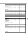
Electric
characteristics
Input conditions
Input voltage :AC100V to AC240V
Frequency : 50-60 Hz
Input current (rating): 1.3A
Output conditions
Output voltage (rating): DC24V ± 5%
Output current (rating): 2.1A
Case specifications
Dimensions
68 × 136 × 33 mm {2.68 × 5.35 × 1.30"}
(H × W × D)
(excluding projections)
Weight
Approx. 0.4 kg {14.11 oz} (excluding the AC cable)
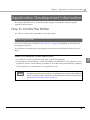
Color
Black (matte)
For Energy Star printers, always use the power supply that came with your printer.
For detailed information about the PS-180, see the instruction manual for the PS-180.
40
Chapter 2 Setup
Setup
This chapter describes setup and installation of the product and peripherals.
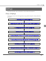
Flow of Setup
This chapter consists of the following sections, along with the setup flow of the product and
peripherals.
1. Installing the Printer (page 42)
2. Adjusting the Paper Roll Near-End (NE) Sensor (page 43)
2
3. Changing the Paper Width (page 44)
4. Setting the DIP Switches (page 45)
5. Connecting the Printer to the Host Computer (page 53)
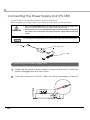
6. Connecting the Power Supply Unit (PS-180) (page 62)
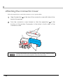
7. Attaching the Connector Cover (page 64)
8. Setting the Memory Switches/Receipt Enhancement (page 65)
9. Connecting the Cash Drawer (page 71)
41
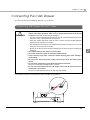
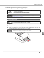
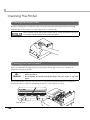
Installing the Printer
Important Notes
• The printer must be installed horizontally on a flat surface (not tilted).
• Do not place the printer in dusty locations.
• Do not knock or strike the printer. This may cause printing errors.
• Do not place any liquids or drinks on the printer case.
• Do not install the printer near any magnetic fields, because this may cause MICR reading
errors. Especially when the printer is used near the display device, the user is required to
check the recognition rate of the MICR.
42
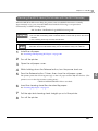
Chapter 2 Setup
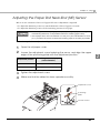
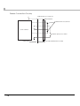
Adjusting the Paper Roll Near-End (NE) Sensor
Below are two situations where a roll paper NE sensor adjustment is required.
• To adjust the detection position to suit the diameter of the roll paper core used.
• To adjust the detection position of the remaining amount of roll paper.
• Since roll paper cores vary slightly in shape, depending on paper roll design and
manufacturing tolerances, it is impossible to detect the remaining paper exactly.
• Use roll paper with a core inner diameter of 12 mm {0.47"} and outer diameter of 18 mm
{0.71"} so that the NE sensor can detect the remaining paper as accurately as possible.
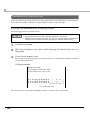
Follow the steps below to adjust the roll paper near-end sensor.
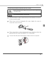
1
2
Open the roll paper cover.
Loosen the adjustment screw fastening the sensor, and align the upper
edge of the positioning plate with the adjustment position.
Adjustment position
Remaining amount of paper
(outer diameter)
Upper
Approx. 27 mm {1.06"}
Lower (Initial setting)
Approx. 23 mm {0.91"}
3
Tighten the adjustment screw.
4
Make sure that the detection lever operates smoothly.
Adjustment screw
Positioning
plate
Detection lever
43
2
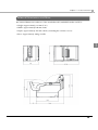
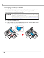
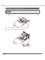
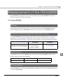
Changing the Paper Width
The printer is initially set to print on 80 mm {3.15"} width paper, but you can change the printer
to print on 58 mm {2.28"} width paper by installing the optional roll paper guide.
Follow the steps below to install the roll paper guide.
• Because some parts of the print head and the autocutter contact the platen and they
may become worn out in 58 mm printing, once you change the paper width from 80 mm
to 58 mm, you cannot change it back to 80 mm.
• When changing the paper width, be sure to change the setting for the paper width with
the customized value. To set the customized value, see "Setting the Memory Switches/
Receipt Enhancement" on page 65
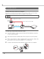
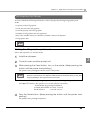
1
2
44
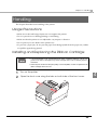
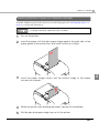
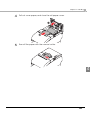
Open the roll paper cover.
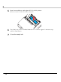
Align 3 projections on the paper guide with the holes in the roll paper
holder, and push it until it clicks into place.
Chapter 2 Setup
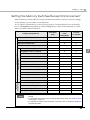
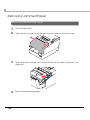
Setting the DIP Switches
On this printer, you can make various settings with DIP switches.
Functions of the DIP switches differ depending on the interface.
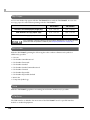
Setting Procedure
Follow the steps below to change the DIP switch settings.
Before you remove the DIP switch cover, turn the printer off.
Otherwise, a short-circuit may cause the printer to malfunction.
CAUTION
DIP switch settings are enabled only when the power is turned on or the printer is reset via
the interface. If the settings are changed after that, the functions will not change.
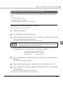
1
2
2
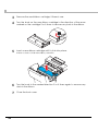
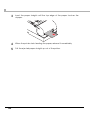
Make sure the power supply for the printer is turned off.
Unscrew the screw to remove the DIP switch cover from the base of the
printer.
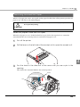
3
Set the DIP switches, using the tip of a tool, such as a small screwdriver.
4
Replace the DIP switch cover, and screw it in place.
45
For Serial Interface
DIP Switch Bank 1
ON
OFF
Initial
setting
Data reception error
Ignored
Prints “?”
OFF
1-2
Receive buffer capacity
45 bytes
4 KB
OFF
1-3
Handshaking
XON/XOFF
DTR/DSR
OFF
1-4
Word length
7 bits
8 bits
OFF
1-5
Parity check
Yes
No
OFF
1-6
Parity selection
Even
Odd
OFF
SW
Function
1-1
1-7
Transmission speed selections
1-8
See the “ Transmission Speed (DIP Switches
1-7/1-8)” table below.
ON
OFF
Transmission Speed (DIP Switches 1-7/1-8)
Transmission speed (bps: bits per second)
SW 1-7
SW 1-8
4800
ON
ON
9600
OFF
ON
19200 (initial setting)
ON
OFF
Setting with the memory switch*:
2400, 4800, 9600, 19200, 38400 (initial setting), 57600, 115200
OFF
OFF
bps: bits per second
* When DIP switches 1-7 and 1-8 are set to OFF, the value (initially 38400) can be set to any of the
values listed in the lower portion of the row using a command, memory switch setting mode, or
the TM-H6000IV Utility. (See "Setting the Memory Switches/Receipt Enhancement" on page 65.)
Depending on print conditions, such as print duty, print head temperature, and data
transmission speed, print speed is automatically adjusted, which can cause white lines due
to intermittent print (the motor sometimes stops). To avoid this, set the transmission speed
higher or keep the print speed constant by setting it lower. (See "Setting the Memory
Switches/Receipt Enhancement" on page 65.)
46
Chapter 2 Setup
DIP Switch Bank 2
SW
Function
ON
2-1
Handshaking (BUSY condition)
Receive buffer full
2-2
Customer display (DM-D)
connection
Connected
2-3 ∼
2-4
Selects print density
2-5 ∼
2-6
Reserved
OFF
• Offline
• Receive buffer full
Not connected
Initial
setting
OFF
OFF
See "Selecting the Pr int Density (DIP
Switches 2-3/2-4)" on page 51.
OFF
Fixed to OFF
OFF
2-7
I/F pin 6 reset signal
Enabled
Disabled
OFF
2-8
IF pin 25 reset signal
Enabled
Disabled
OFF
2
For DIP switch 2-1 (BUSY condition), see also "Selecting the BUSY Status" on page 52.
47
For Parallel Interface
DIP Switch Bank 1
SW
Function
1-1
Auto line feed
1-2
Receive buffer capacity
1-3 ∼
1-8
ON
OFF
Initial
setting
Always enabled
Always disabled
OFF
45 bytes
4 KB
OFF
Reserved
Fixed to OFF
OFF
DIP Switch Bank 2
SW
Function
ON
OFF
2-1
Handshaking (BUSY condition)
Receive buffer full
2-2
Reserved
• Offline
• Receive buffer full
Initial
setting
OFF
Fixed to OFF
OFF
See "Selecting the Pr int Density (DIP
Switches 2-3/2-4)" on page 51.
OFF
2-3 ∼
2-4
Selects print density
2-5 ∼
2-7
Reserved
Fixed to OFF
OFF
IF pin 31 reset signal
Fixed to ON
ON
2-8
For DIP switch 2-1 (BUSY condition), see also "Selecting the BUSY Status" on page 52.
48
Chapter 2 Setup
For Built-in USB Interface
DIP Switch Bank 1
SW
Function
1-1
Auto line feed
1-2
Receive buffer capacity
1-3 ∼
1-7
1-8
ON
OFF
Factory
setting
Always enabled
Always disabled
OFF
45 bytes
4 KB
OFF
Reserved
Fixed to OFF
Setting of USB power-saving
function*
Disabled
OFF
Enabled
OFF
*: Valid only when the system configuration is set so that the USB driver can support the USB power-saving
2
function.
DIP Switch Bank 2
SW
Function
ON
2-1
Handshaking (BUSY condition)
Receive buffer full
2-2
Customer display (DM-D)
connection
Connected
2-3 ∼
2-4
Selects print density
2-5 ∼
2-7
2-8
OFF
• Offline
• Receive buffer full
Not connected
Factory
setting
OFF
OFF
See "Selecting the Pr int Density (DIP
Switches 2-3/2-4)" on page 51.
OFF
Reserved
Fixed to OFF
OFF
Reserved
Fixed to ON
ON
For DIP switch 2-1 (BUSY condition), see also "Selecting the BUSY Status" on page 52.
49
For Ethernet/Wireless LAN Interface
DIP Switch Bank 1
SW
Function
1-1
Auto line feed
1-2
Receive buffer capacity
1-3 ∼
1-8
ON
OFF
Initial
setting
Always enabled
Always disabled
OFF
45 bytes
4 KB
OFF
Reserved
Fixed to OFF
OFF
DIP Switch Bank 2
SW
Function
ON
OFF
2-1
Handshaking (BUSY condition)
Receive buffer full
2-2
Reserved
• Offline
• Receive buffer full
Initial
setting
OFF
Fixed to OFF
OFF
See "Selecting the Pr int Density (DIP
Switches 2-3/2-4)" on page 51.
OFF
2-3 ∼
2-4
Selects print density
2-5 ∼
2-7
Reserved
Fixed to OFF
OFF
2-8
Reserved
Fixed to ON
ON
For DIP switch 2-1 (BUSY condition), see also "Selecting the BUSY Status" on page 52.
50
Chapter 2 Setup
Selecting the Print Density (DIP Switches 2-3/2-4)
Function
SW 2-3
SW 2-4
Print density (standard)
OFF
OFF
Print density (darker than standard)
ON
OFF
Print density (dark)
OFF
ON
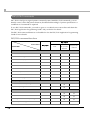
Depending on the paper type, it is recommended to set the print density as shown in the table
below for the best print quality.
Original Paper Type
Density Level
TF 50KS- E, TF 60KS- E, PD150R, PD 160R, P D190R,
P220AGB-1, AF50KS-E, KT48F20, KT55F20, F5041, P350
Standard
P300, P310
Darker than standard
• If the print density is set to “Darker than standard” or “Dark” level, printing speed may be
reduced.
• If the print density is set to “Darker than standard” or “Dark” level, paper dust will
accumulate on the print head and print may be faint. For information on how to clean the
thermal head, see "Cleaning the Thermal Head" on page 106.
• The print density can be set with DIP switches (2-3/2-4) or the customized value. (See
"Setting the Memory Switches/Receipt Enhancement" on page 65.) The initial setting of
the customized value is “Depends on the DIP switch settings.” If the customized value is
changed, the value set with the customized value is enabled.
51
2
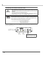
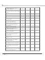
Selecting the BUSY Status
With DIP switch 2-1, you can select conditions for invoking a BUSY state as either of the
following:
• When the receive buffer is full
• When the receive buffer is full or the printer is offline
In either case above, the printer enters the BUSY state after power is turned on (including
resetting with the interface) and when a self-test is being run.
Printer BUSY Condition and Status of DIP Switch 2-1
DIP SW 2-1
Printer status
Offline
ON
OFF
During the period after the power is turned on
(including resetting with the interface) to when
the printer is ready to receive data.
BUSY
BUSY
During the self-test.
BUSY
BUSY
When the cover is open.
—
BUSY
During paper feed with the Feed button.
—
BUSY
When the printer stops printing due to a paperend (when printer has run out of roll paper).
—
BUSY
When an error has occurred.
—
BUSY
BUSY
BUSY
When the receive buffer becomes full.
If BUSY condition is set to “Receive buffer full,” the printer will not become BUSY
• When the cover is open
• When paper is fed by the FEED button
• When printing has stopped for a paper-end
• When an error has occurred
52
Chapter 2 Setup
Connecting the Printer to the Host Computer
• Be sure to install the driver before connecting the printer to the host computer.
• The printer uses modular connectors specifically designed for the cash drawer and the
customer display. Do not connect an ordinary telephone line to these connectors.
For Serial Interface
Serial interface connection diagram
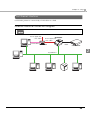
When this printer and the customer display (DM-D) are connected to a host computer by the
serial interface, three connection forms are possible:
• Stand-alone connection
• Pass-through connection
2
• Y connection
The modular cable is connected to the cash drawer and/or the customer display.
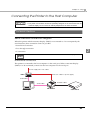
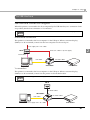
Stand-alone connection
This printer is connected to the host computer via the serial port. When a customer display
(DM-D) is to be connected, connect it to the host computer via the serial port.
Power supply unit + AC cable
DM-D
Extension cable for power supply
Serial cable
Modular cable
Serial cable
TM-H6000IV
Cash drawer
53
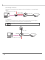
Pass-through connection
This printer is connected to the host computer over the serial interface via a customer display
(DM-D).
Power supply unit + AC cable
Extension cable
for power supply
Serial cable
Modular cable
Serial cable
DM-D
TM-H6000IV
Cash drawer
Y connection
This printer is connected to the host computer via the serial port. When a customer display
(DM-D) is to be connected, connect it to the printer via the modular cable.
A mount-type customer display also can be directly connected to the printer.
DM-D
Modular cable
TM-H6000IV
Modular cable
Serial cable
Power supply unit + AC cable
54
Cash drawer
Chapter 2 Setup
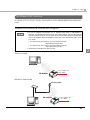
Connecting the serial interface (RS-232) cable
Be sure to turn off the power supply for both the printer and host computer before
connecting the cables.
WARNING
Use a null modem serial cable to connect the printer.
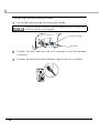
1
2
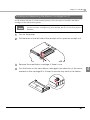
Insert the interface cable connector firmly into the interface connector
on the connector panel.
When using connectors equipped with screws, tighten the screws to
secure the connectors firmly.
2
3
4
When using interface cables equipped with a grounding line, attach the
ground line to the screw hole marked “FG” on the printer.
Connect the other end of the interface cable to the host computer.
55
For Parallel Interface
Parallel interface connection diagram
This printer is connected to the host computer via the parallel port. When a customer display
(DM-D) is to be connected, connect it to the host computer via the serial port.
The modular cable is connected to the cash drawer.
Power supply unit + AC cable
DM-D
Extension cable for power supply
Serial cable
Modular cable
Parallel cable
TM-H6000IV
Cash drawer
Connecting the parallel interface cable
1
2
3
4
56
Insert the interface cable connector firmly into the interface connector
on the connector panel.
Press down the clips on either side of the connector to lock it in place.
When using interface cables equipped with a ground line, attach the
ground line to the screw hole marked “FG” on the printer.
Connect the other end of the interface cable to the host computer.
Chapter 2 Setup
For USB Interface
USB interface connection diagram
When this printer is connected to the host computer by the USB interface, two connection forms
are possible, Stand-alone connection or Y connection.
The modular cable is connected to the cash drawer and/or the customer display.
Stand-alone connection
This printer is connected to the host computer via the USB port. When a customer display
(DM-D) is to be connected, connect it to the host computer via the serial port.
Power supply unit + AC cable
DM-D
2
Extension cable for power supply
Serial cable
Modular cable
USB cable
TM-H6000IV
Cash drawer
Y connection
This printer is connected to the host computer via the USB port. When a customer display
(DM-D) is to be connected, connect it to the printer via the modular cable.
A mount-type customer display also can be directly connected to the printer.
DM-D
Modular cable
TM-H6000IV
USB cable
Power supply unit + AC cable
Modular cable
Cash drawer
57
Connecting the USB interface cable
1
Put the USB cable through the locking wire saddle.
Putting the USB cable through the locking wire saddle, as shown in the figure below,
prevents the cable from coming unplugged.
Locking wire saddle
USB cable
2
3
58
Connect the USB cable from the host computer to the USB upstream
connector.
Connect the other end of the interface cable to the host computer.
Chapter 2 Setup
For Ethernet Interface
Connect the printer to a network by a LAN cable via a hub.
Ethernet interface connection diagram
The modular cable is connected to the cash drawer.
Power supply unit
+ AC cable
TM-H6000IV
Power supply unit
+ AC cable
Modular
cable
Serial cable
DM-D
Cash drawer
2
10/100BASE-T
59
Connecting the Ethernet interface cable
CAUTION
• When LAN cables are installed outdoors, make sure devices without proper surge
protection are cushioned by being connected through devices that do have surge
protection.
Otherwise, the devices can be damaged by lightning.
• Never attempt to connect the customer display cable, drawer kick-out cable, or a
standard telephone line cable to the 10/100BASE-T LAN connector.
To use the Ethernet interface, the IP Address Setup Utility for UB-E02 is required. For
detailed information about the setup methods, see the UB-E02 Technical Reference Guide.
You can obtain the IP Address Setup Utility for UB-E02 and the UB-E02 Technical
Reference Guide from one of the following URLs or ask your dealer:
• For customers in North America, go to the following web site:
http://www.epsonexpert.com/
• For customers in other countries, go to the following web site:
http://www.epson-pos.com/
Connect a 10/100BASE-T cable to the 10/100BASE-T LAN connector by pressing firmly until the
connector clicks into place.
10/100BASE-T LAN
interface connector
016(146'.'%1//70+%#6+1075'
-'+06'.'(10#05%*.755/
LED
(Green)
60
LED
(Yellow)
Switch
Press down the switch for a
while when the power is on to
initialize to the factory settings.
Chapter 2 Setup
For Wireless LAN Interface
For details on how to set up a wireless LAN interface, see the UB-R02/R03 Technical Reference
Guide.
Wireless LAN interface connection diagram
• To use the wireless LAN interface, the IP Address Setup Utility for UB-R02/R03 is
required. For detailed information about the setup methods, see the UB-R02/R03
Technical Reference Guide. You can obtain the IP Address Setup Utility for UB-R02/R03
and the UB-R02/R03 Technical Reference Guide from one of the following URLs or ask
your dealer:
∗ For customers in North America, go to the following web site:
http://www.epsonexpert.com/
∗ For customers in other countries, go to the following web site:
http://www.epson-pos.com/
• Initial setting of the UB-R02 is ad hoc mode.
Ad hoc mode
Power supply unit
+ AC cable
TM-H6000IV
Infrastructure mode
Access point
TM-H6000IV
Power supply unit
+ AC cable
61
2
Connecting the Power Supply Unit (PS-180)
Use the PS-180 or an equivalent product as the power supply unit.
Before using the power supply unit, read carefully the user’s manual enclosed with it.
WARNING
• Always use the EPSON PS-180 or an equivalent product as the power supply unit.
Using a nonstandard power supply can result in electric shock and fire.
• Should a fault ever occur in the EPSON PS-180 or equivalent product, immediately
turn off the power to the printer and unplug the power supply cable from the wall
socket.
For an Energy Star-compliant printer, use only the power supply that came with the printer.
DC cable
Power supply unit
AC cable
Connecting the Power Supply Unit
1
2
62
Make sure the printer’s power supply is turned off and the AC cable has
been unplugged from the wall socket.
Insert the connector of the DC cable onto the power supply connector.
Chapter 2 Setup
3
Connect the plug of the AC cable to the wall socket.
WARNING
• Be sure to unplug the AC cable from the wall socket whenever connecting or
disconnecting the power supply unit to the printer.
Failure to do so may result in damage to the power supply unit or the printer.
• Make sure the wall socket power supply satisfies the rated voltage requirements
of the power supply unit. Never insert the power supply cable plug into a socket
that does not meet the rated voltage requirements of the power supply unit.
Doing so may result in damage to both the power supply and the printer.
Do not turn on the printer before installing the printer driver.
63
2
Attaching the Connector Cover
Follow the steps below to attach the connector cover to protect cables.
1
2
Align 2 projections A on the top of the connector cover with holes in the
back of the printer.
Push the connector cover forward so that the projections B at the
bottom of the printer fit properly in the holes in both sides of the
connector cover.
A
B
To remove the connector cover, push both sides of the cover inward to release the holes in
both sides of the cover from the projections at the bottom of the printer.
64
Chapter 2 Setup
Setting the Memory Switches/Receipt Enhancement
With the memory switch and R/E (receipt enhancement) function, which are software settings
for this printer, you can set the various functions.
For an outline of the functions, see the following section. Use the methods shown in the table
below; TM-H6000IV Utility, Memory Switch Setting Mode, or ESC/POS commands, to set the
memory switches and R/E functions.
Memory
Switch
Setting Mode
ESC/POS
Commands
Power on notice
✔
✔
Error signal output
✔
✔
Slip paper jam detection
✔
✔
Receipt unit open during printing
✔
✔
User NV memory capacity
✔
✔
NV graphics memory capacity
✔
✔
Interface selection
✔
✔
TM-H6000IV
Utility
Customized Values
2
✔
Number of head energizing parts
Receipt
Enhancement
Memory Switches
Settings\Setting Methods
Roll paper width
✔
✔
✔
Receipt print density
✔
✔
✔
Receipt print speed
✔
✔
✔
Command execution during offline
✔
✔
✔
Power supply unit capacity
✔
✔
✔
Autocutting at roll paper cover close
✔
✔
✔
Automatic paper reduction
✔
✔
✔
Print density in multi-tone printing
✔
✔
✔
Transmission speed for serial interface
✔
✔
✔
Automatic top logo printing
✔
✔
Automatic bottom logo printing
✔
✔
Top logo printing at cover close
✔
✔
Top logo printing at power on
✔
✔
• For detailed information about the TM-H6000IV Utility, see the TM-H6000IV Utility User’s
Manual.
• For information about how to use the memory switch setting mode, see "Memory Switch
Setting Mode" on page 93.
• For detailed information about ESC/POS commands, see the ESC/POS Application
Programming Guide.
65
Functions
Power on notice
• Transmits (initial setting)
• Does not transmit
Error signal output
• Enabled (initial setting)
• Disabled
This function is valid only when using the parallel interface.
Slip paper jam detection
• Enabled (initial setting)
• Disabled
Receipt unit open during printing
• Offline (initial setting)
• Recoverable error
User NV memory capacity
• 1 KB (initial setting)
• 64 KB
• 128 KB
• 192 KB
66
Chapter 2 Setup
NV graphics memory capacity
• None
• 64 KB
• 128 KB
• 192 KB
• 256 KB
• 320 KB
• 384 KB (initial setting)
Interface selection
Selectable from: automatic selection, fixed to UB interface, or fixed to built-in USB.
The TM-H6000IV has dual interfaces: a built-in USB interface and another interface
selected by the customer. (The selectable interface is referred to as the "UB" interface.)
The tables below describe the modes you can set for the printer to control the dual
interfaces.
For models with serial/parallel UB
Interface mode
UB
Built-in USB
Automatic selection (initial setting)
Available
Available
Fixed to UB
Available
Not available
Not available
Available
UB
Built-in USB
Automatic selection
Available
Not available
Fixed to UB (initial setting)
Available
Not available
Not available
Available
Fixed to built-in USB
For models with other UB
Interface mode
Fixed to built-in USB
Automatic selection:
The interface of either the UB or built-in USB to which data is transmitted first is selected.
Once the interface is selected, the selection is enabled until the power is turned off or the
printer is reset.
67
2
Number of head energizing parts
• One-part energizing (initial setting)
• Two-part energizing
• Four-part energizing
• Usually, the number of head energizing parts does not need to be changed.
• The maximum print speed (300 mm/s) can be performed only when one-part energizing
is selected.
Roll paper width
• 80 mm (initial setting)
• 58 mm
• Be sure to install the roll paper guide (model: PG-58II) when you select the 58 mm paper
width. (See "Changing the Paper Width" on page 44.)
• Because some parts of the print head and the autocutter contact the platen and they
may become worn out in 58 mm printing, once you change the paper width from 80 mm
to 58 mm, you cannot change it back to 80 mm.
Receipt print density
Selectable from levels 1 to 13 (70% ∼ 130%) (initial setting: level 7)
Depending on the paper type, it is recommended to set the print density as shown in the table
below for the best print quality.
Original Paper Type
Density Level
AF50KS-E
4 (85%)
TF50KS-E, P220AGB-1
5 (90%)
P350
6 (95%)
TF60KS-E, PD150R, PD160R, PD190R, KT48F20, KT55F20,F5041
7 (100%)
P300, P310
8 (105%)
• If the print density is set to a darker level, printing speed may be reduced.
• If the print density is set to a darker level, paper dust accumulates on the print head and
print may be faint. For information on how to clean the thermal head, see "Cleaning the
Thermal Head" on page 106.
• The print density can be set with DIP switches (2-3/2-4) or the customized value. (See
"Selecting the Print Density (DIP Switches 2-3/2-4)" on page 51.) The initial setting of the
customized value is “Depends on the DIP switch settings.” If the customized value is
changed, the value set with the customized value is enabled.
68
Chapter 2 Setup
Receipt print speed
Selectable from levels 1 to 13 (Slow ∼ Fast) (initial setting: level 13)
Depending on print conditions, such as print duty, print head temperature, and data
transmission speed, print speed is automatically adjusted, which may cause white lines due
to intermittent print (the motor sometimes stops). To avoid this, keep the print speed
constant by setting it lower, or set the transmission speed higher for the serial interface.
(See "Transmission Speed (DIP Switches 1-7/1-8)" on page 46.)
Command execution during offline
When this function is enabled, you can execute specified commands even if the printer is offline
due to specified causes.
• Enabled
• Disabled (initial setting)
For the combination of the offline causes and executable commands, see the ESC/POS
Application Programming Guide.
Power supply unit capacity
Selectable from levels 1 to 3 (Low ∼ High) (initial setting: level 3)
Autocutting at roll paper cover close
• Cuts
• Does not cut (initial setting)
Automatic paper reduction
• Extra upper space reduction: disabled (initial setting) or enabled
• Extra lower space reduction: disabled (initial setting) or enabled
• Line space reduction rate: not reduced (initial setting), 25%, 50%, or 75%
• Line feed reduction rate: not reduced (initial setting), 25%, 50%, or 75%
• Barcode height reduction rate: not reduced (initial setting), 25%, 50%, or 75%
Print density in multi-tone printing
Selectable from levels 1 to 13 (70% ∼ 130%) (initial setting: level 7)
Depending on the paper type, it is recommended to set the print density for the best print
quality.
69
2
Transmission speed for serial interface
When DIP switches 1-7 and 1-8 are set to ON, the value (initially 38400) can be set to 2400, 4800,
9600, 19200, 38400, 57600, or 115200. (See "Transmission Speed (DIP Switches 1-7/1-8)" on page
46.)
The transmission speed can be set with DIP switches 1-7 and 1-8 (See "Transmission
Speed (DIP Switches 1-7/1-8)" on page 46.) or the customized value. When DIP switches
1-7 and 1-8 are set to OFF, the setting with the customized value is enabled.
Automatic top logo printing
Key code
Selectable from key codes of registered logos
Alignment
• Left
• Center
• Right
Automatic bottom logo printing
Key code
Selectable from key codes of registered logos
Alignment
• Left
• Center
• Right
Top logo printing at cover close
• Enabled (initial setting)
• Disabled
Top logo printing at power on
• Enabled
• Disabled (initial setting)
70
Chapter 2 Setup
Connecting the Cash Drawer
Use the cash drawer handled by EPSON or your dealer.
Connecting the Drawer Kick-out Cable
WARNING
• Specifications of drawers differ depending on makers or models. When you use a
drawer other than specified, make sure its specification meets the following
conditions. Otherwise, devices may be damaged.
∗ The load, such as a drawer kick-out solenoid, must be connected between pins 4 and
2 or pins 4 and 5 of the drawer kick-out connector.
∗ When the drawer open/close signal is used, a switch must be provided between
drawer kick-out connector pins 3 and 6.
∗ The resistance of the load, such as a drawer kick-out solenoid, must be 24 Ω or more
or the input current must be 1A or less.
∗ Be sure to use the 24V power output on drawer kick-out connector pin 4 for driving the
equipment.
• Use a shield cable for the drawer connector cable.
• Two driver transistors cannot be energized simultaneously.
• Leave intervals longer than 4 times the drawer driving pulse when sending it
continuously.
• Be sure to use the printer power supply (connector pin 4) for the drawer power
source.
• Do not insert a telephone line into the drawer kick-out connector.
Doing so may damage the telephone line or printer.
• Do not connect the USB connector (“B” Plugs of the series B connectors) to the
drawer kick-out connector.
Doing so may damage the printer or the host computer system.
Connect the connector of the drawer kick-out cable to the printer.
71
2
Drawer Connection Circuitry
Drawer kick-out connector
()
With shielded
Drawer kick-out solenoid
8
Control device
Drawer open/close switch
Printer side
72
User side [Drawer kick-out side]
Chapter 3 Application Development Information
Application Development Information
This chapter describes how to control the printer and gives information useful for printer
application development.
How to Control the Printer
Use a driver or ESC/POS commands to control the printer.
Selecting a Driver
Choose one of the drivers listed in "Printer Drivers" on page 83, depending on the application
operating environment.
For information about the driver operating environment, see the installation manual for each
driver.
When you develop a new application
• Use APD if you want to print True Type fonts or print many graphics.
• OPOS ADK is recommended for system extensibility. An OPOS driver is provided for various
peripherals and it is a POS industry standard now. It enables POS system efficiency, reduction
of development cost, and effective use of application assets.
You can use all functions, including ones not supported by OPOS ADK or APD, by using
ESC/POS commands through your driver. Use the DIRECT I/O function of OPOS ADK, the
control A command of APD, or Status API to send ESC/POS commands from each driver.
(See "ESC/POS command functions" on page 74.)
73
3
ESC/POS Commands
ESC/POS is the Epson original printer command system. With ESC/POS commands, you can
directly control all the TM printer functions, but detailed knowledge of printer specifications or
combination of commands is required.
To use ESC/POS commands, you need to agree to a nondisclosure contract first and obtain the
ESC/POS Application Programming Guide. Ask your dealer for details.
The ESC/POS command functions are listed below. See the ESC/POS Application Programming
Guide for more details.
ESC/POS command functions
Slip paper
Active sheet
Front
Endorsement
40 cpl mode
disabled
40 cpl mode
enabled
Roll paper
Commands
Print commands
Print and line feed
✔
✔
✔
✔
Print and carriage return
✔
✔
✔
✔
Print and feed paper
✔
✔
✔
✔
✔
✔
✔
Print and reverse feed
Print and feed n lines
✔
✔
✔
✔
Print and reverse feed n lines
✔
✔
✔
✔
✔
✔
✔
✔
Print and eject cut sheet
Print and return to standard mode
✔
✔
Print data in page mode
✔
✔
✔
Select default line spacing
✔
✔
✔
Set line spacing
✔
✔
✔
Select character code table
✔
✔
✔
✔
Select an international character set
✔
✔
✔
✔
Set right-side character spacing
✔
✔
✔
✔
Select print mode(s)
✔
✔
✔
Line spacing commands
Character commands
74
Chapter 3 Application Development Information
Turn underline mode on/off
✔
✔
✔
Turn emphasized mode on/off
✔
✔
✔
Select character font
✔
✔
✔
Select character size
✔
✔
✔
Turn smoothing mode on/off
✔
Turn double-strike mode on/off
✔
✔
✔
Turn upside-down print mode on/off
✔
✔
✔
Turn 90° clockwise rotation mode on/off
✔
Turn white/black reverse print mode
on/off
✔
Select/cancel user-defined character
set
✔
✔
✔
Define user-defined characters
✔
✔
✔
Cancel user-defined characters
✔
✔
✔
Cancel print data in page mode
✔
✔
✔
3
Printing paper commands
Select the side of the slip
✔
✔
✔
Feed to the print starting position for
the slip
✔
✔
✔
Select paper type(s) for printing
✔
✔
✔
✔
Select paper type(s) for command
settings
✔
✔
✔
✔
Set cut sheet wait time
✔
✔
✔
✔
✔
✔
✔
✔
Select paper sensor(s) to stop printing
✔
✔
✔
✔
Select paper sensor(s) to output paperend signals
✔
✔
✔
✔
Horizontal tab
✔
✔
✔
✔
Set horizontal tab positions
✔
✔
✔
✔
Panel button commands
Enable/disable panel buttons
Paper sensor commands
Print position commands
75
Set left margin
✔
✔
✔
Set print area width
✔
✔
✔
Select justification
✔
✔
✔
Set absolute print position
✔
✔
✔
Set relative print position
✔
✔
✔
Set print position to the beginning of
print line
✔
✔
✔
Set print area in page mode
✔
✔
Select print direction in page mode
✔
✔
Set absolute vertical print position in
page mode
✔
✔
Set relative vertical print position in
page mode
✔
✔
Transmit the NV graphic memory
capacity
✔
✔
Print the graphics data in the print
buffer
✔
Transmit the remaining capacity of the
NV graphics memory
✔
✔
Transmit the key code list for defined
NV graphics
✔
✔
Delete all NV graphics data
✔
✔
Delete the specified NV graphics data
✔
✔
Define the NV graphics data (raster
format)
✔
✔
Print the specified NV graphics data
✔
✔
Transmit the key code list for defined
download graphics
✔
✔
Delete all download graphics data
✔
✔
Delete the specified download
graphics data
✔
✔
Define the NV graphics data (raster
format)
✔
✔
Bit image commands
76
✔*1
✔
✔
Chapter 3 Application Development Information
Print the specified download graphics
data
✔
Store the graphics data in the print
buffer (raster format)
✔
Specify Windows BMP NV graphics
data
✔
Specify Windows BMP download
graphics data
✔
Select bit-image mode
✔
✔
✔
✔
Enable/disable Automatic Status Back
(ASB)
✔
✔
✔
✔
Customize ASB-status bits
✔
✔
✔
✔
Transmit status
✔
✔
✔
✔
Transmit real-time status
✔
✔
✔
✔
Enable/disable Automatic Status Back
(ASB) for optional functions (extended
status)
✔
✔
✔
✔
Print bar code
✔
✔*2
Set bar code height
✔
✔
Set bar code width
✔
✔
Select print position of HRI characters
✔
Select font for HRI characters
✔
✔
Status commands
3
Bar code commands
✔
✔
✔
✔
✔
✔
✔
✔
Two-dimensional code commands
PDF417: Set the number of columns in
the data region
✔
PDF417: Set the number of rows
✔
PDF417: Set the width of the module
✔
PDF417: Set the row height
✔
PDF417: Set the error correction level
✔
PDF417: Select the options
✔
PDF417: Store the data in the symbol
storage area
✔
77
78
PDF417: Print the symbol data in the
symbol storage area
✔
PDF417: Transmit the size information of
the symbol data in the symbol storage
area
✔
QR Code: Select the model
✔
QR Code: Set the size of the module
✔
QR Code: Set the error correction level
✔
QR Code: Store the data in the symbol
storage area
✔
QR Code: Print the symbol data in the
symbol storage data area
✔
QR Code: Transmit the size information
of the symbol data in the symbol
storage area
✔
MaxiCode: Select the mode
✔
MaxiCode: Store the data in the
symbol storage area
✔
MaxiCode: Print the symbol data in the
symbol storage area
✔
MaxiCode: Transmit the size information
of the symbol data in the symbol
storage area
✔
Two-dimensional GS1 DataBar: Set the
width of module
✔
Two-dimensional GS1 DataBar: Set the
maximum width of GS1 DataBar
Expanded Stacked
✔
Two-dimensional GS1 DataBar: Store
the data in the symbol storage area
✔
Two-dimensional GS1 DataBar: Print the
symbol data in the symbol storage
area
✔
Two-dimensional GS1 DataBar: Transmit
the size information of the symbol data
in the symbol storage area
✔
Chapter 3 Application Development Information
Composite Symbology: Set the width of
module
✔
Composite Symbology: Set the
maximum width of GS1 DataBar
Expanded Stacked
✔
Composite Symbology: Select font for
HRI characters
✔
Composite Symbology: Store the data
in the symbol storage area
✔
Composite Symbology: Print the symbol
data in the symbol storage area
✔
Composite Symbology: Transmit the
size information of the symbol data in
the symbol storage area
✔
Macro function commands
Start/end macro definition
✔
✔
✔
✔
Execute macro
✔
✔
✔
✔
✔
✔
✔
✔
✔
✔
✔
Mechanism control commands
Turn unidirectional print mode on/off
Return home
Set/cancel cut sheet reverse eject
✔
✔
✔
✔
Release paper
✔
✔
✔
✔
Select cut mode and cut paper
✔
3
Customized commands
Change into the user setting mode
✔
✔
✔
✔
End the user setting mode session
✔
✔
✔
✔
Change the setting of the memory
switch
✔
✔
✔
✔
Transmit the setting of the memory
switch
✔
✔
✔
✔
Set the customized setting values
✔
✔
✔
✔
Transmit the customized setting values
✔
✔
✔
✔
Set the transmission conditions for the
serial interface
✔
✔
✔
✔
79
Transmit the transmission conditions for
the serial interface
✔
✔
✔
✔
Save the setting values from the work
area into the storage area
✔
✔
✔
✔
Load the setting values stored in the
storage area to the work area
✔
✔
✔
✔
Select the setting values loaded to the
work area after the initialization process
✔
✔
✔
✔
Delete the specified record
✔
✔
✔
✔
Store the data in the specified record
✔
✔
✔
✔
Transmit the data in the specified
record
✔
✔
✔
✔
Transmit capacity of the NV user
memory currently being used
✔
✔
✔
✔
Transmit the remaining capacity of the
NV user memory
✔
✔
✔
✔
Transmit the key code list
✔
✔
✔
✔
Delete all data in the NV user memory
✔
✔
✔
✔
Set 40 cpl mode
✔
✔
✔
✔
Initialize printer
✔
✔
✔
✔
Transmit printer ID
✔
✔
✔
✔
Set horizontal and vertical motion units
✔
✔
✔
✔*1
Select peripheral device
✔
✔
✔
✔
Generate pulse
✔
✔
✔
✔
Generate pulse in real time
✔
✔
✔
✔
Execute power-off sequence
✔
✔
✔
✔
Clear buffer(s)
✔
✔
✔
✔
Enable/disable real-time command
✔
✔
✔
✔
Send real-time request to printer
✔
✔
✔
✔
Select page mode
✔
✔
Miscellaneous commands
✔
Select double-density page mode
Select standard mode
80
✔
✔
Chapter 3 Application Development Information
Enable/disable transmission of paper
status
✔
✔
✔
✔
Execute test print
✔
✔
✔
✔
Select the print speed
✔
Select the number of parts for the
thermal head energizing
✔
Initialize maintenance counter
✔
✔
✔
✔
Transmit maintenance counter
✔
✔
✔
✔
Receipt enhancement commands
Cancel set values for top/bottom logo
printing
✔
Transmit set values for top/bottom logo
printing
✔
Set top logo printing
✔
Set bottom logo printing
✔
Make extended settings for top/
bottom logo printing
✔
Enable/disable top/bottom logo
printing
✔
3
MICR control commands (only for models with the MICR reader)
Transmit real-time status
✔
✔
✔
✔
Select MICR data handling
✔
✔
✔
✔
Read check paper
✔
✔
✔
✔
Load check paper to print starting
position
✔
✔
✔
✔
Eject check paper
✔
✔
✔
✔
Request retransmission of check paper
reading result
✔
✔
✔
✔
Clean MICR mechanism
✔
✔
✔
✔
*1: Fixed value
*2: Only for standard mode
81
Software and Manuals
The following software and manuals are provided for application development.
How to Get Drivers, Manuals, and the Utility
You can obtain drivers, manuals, and the TM-H6000IV Utility from one of the following URLs.
For customers in North America, go to the following web site:
http://www.epsonexpert.com/ and follow the on-screen instructions.
For customers in other countries, go to the following web site:
http://www.epson-pos.com/
Printer Drivers
Software
EPSON Advanced Printer Driver (APD):
• APD Install Manual
In addition to ordinary Windows driver functions, this
driver has controls specific to POS, such as controls for
paper cut, a cash drawer, or customer display. The
Status API (Epson original DLL) that monitors printer
status and sends ESC/POS commands is also
attached to this driver.
• APD TM/BA/EU Printer Manual
OPOS ADK:
• OPOS Installation Manual
This OCX driver can control POS peripherals using OLE
technology*1. Because controlling POS peripherals
with original commands is not required on the
application side, efficient system development is
possible.
• User’s Manual
OPOS ADK for .NET:
• OPOS ADK for .NET Installation Guide
OPOS ADK for .NET allows you to develop
applications that are compatible with Microsoft POS
for .NET.
• UnifiedPOS Retail Peripheral Architecture*2
When developing applications, use a separate
development environment such as Microsoft Visual
Studio .NET.
82
Manual
• APD Printer Specification
• Devmode API/PRINTERINFO Manual
• Status API Manual
• Sample Program Guide
• Application Development Guide
• UnifiedPOS Retail Peripheral Architecture*2
• Sample Program Guide
• User's Reference (SetupPOS)
• Application Development Guide
(POSPrinter TM-H6000IV)
Chapter 3 Application Development Information
Software
JavaPOS ADK:
Manual
JavaPOS ADK Installation Guide
JavaPOS is the standard specification which defines
an architecture and device interface (API) to access
various POS devices from a Java based system. Using
JavaPOS standard API allows control with Java-based
applications of functions inherent to each device. A
flexible design with Java language and JavaPOS
enables many different types of computer systems,
such as stand alone or network configuration, to use
a same application. You can use JavaPOS to build
applications and drivers independently of platforms.
This allows flexible configurations using thin clients to
meet the system requirements.
EPSON TM Virtual Port Driver:
TM Virtual Port Driver User’s Manual
This driver is a Serial-USB and Parallel-USB conversion
driver to make an EPSON TM/BA/EU printer
connected via USB accessible from a POS
application through virtual COM ports and a virtual
LPT port. Without making changes in the POS
application that controls devices connected through
serial or parallel interfaces, devices connected via
USB can be directly controlled with ESC/POS
commands.
3
*1: OLE technology developed by Microsoft divides software into part blocks. The OPOS driver
is presupposed to be used with a development environment, such as Visual Basic, unlike
ordinary Windows drivers. It is not a driver to be used for printing from commercial
applications.
*2: This guide describes general information on how to control printers using the OPOS ADK (in
the chapter “POS Printer” and “Appendix A”). It does not describe Epson’s specific functions.
83
Utilities
Software
TM-H6000IV Utility:
Manual
• TM-H6000IV Utility User’s Manual
Use for checking and setting the following functions:
• Current settings
• Operation check
• Storing logos
• Paper reduction
• Automatic paper cut
• Printing control
• Communication interface
• Backup/restore
TM-H6000IV Printer Model Setting Utility:
Use to change the printer model name when you use
the TM-H6000IV with the APD Ver. 4.00 ~ 4.04.
TM-H6000IV Printer Model Setting Utility
User's Manual
TM Net WinConfig:
• TM Net WinConfig User’s Guide
Use for IP address or wireless LAN setting.
• UB-E02 Technical Reference Guide
• UB-R02/R03 Technical Reference Guide
EpsonNet Simple Viewer:
EpsonNet Simple Viewer User’s Manual
Use to monitor the network and the printer status.
TM-H6000IV Remote Configuration Tool:
Use to change settings and monitor the status of the
TM-H6000IV connected by parallel/serial/USB to client
computers (POS and KIOSK terminals) from an
administrator computer over the network using
EpsonNet Simple Viewer and the TM-H6000IV Utility.
BMP File Converter:
Use to convert the BMP image files used in Windows
into a data format which can be interpreted by the
TM-H6000IV. Conversion to multi-tone or black and
white image command is possible. After execution, a
binary file with the command string is created.
84
TM/BA/EU Printer Remote Configuration Tool
User’s Manual
Readme
Chapter 3 Application Development Information
Setting/Checking Modes
Besides the ordinary print mode, the printer has the following modes to set or check settings of
the printer.
• Self-test Mode (See page 86.)
• Hexadecimal Dumping Mode (See page 89.)
• NV Graphics Print Mode (See page 90.)
• Receipt Enhancement Information Print Mode (See page 92.)
• Memory Switch Setting Mode (See page 93.)
Self-test Mode
In the self-test mode, the printer prints the current status of the printer (on the roll paper) and
resident characters as a test print (roll paper, slip paper, and validation paper).
You can confirm the following information with the status print.
• ROM version
• Interface setting
• Buffer capacity setting
3
• Busy condition setting
• Automatic line feed setting
• Customer display connection
• Resident character set
• Print density setting
• Installed devices (MICR unit, endorsement printer unit, validation unit)
• Maintenance information (thermal head, autocutter, impact head, MICR head)
• DIP switch settings
85
Starting the status print and test print on the roll paper
Follow the steps below to start a status print and test print on the roll paper.
1
Install the roll paper.
2
Close all covers and the receipt unit.
3
While pressing the Feed button, turn on the printer. (Keep pressing the
button until the printer starts printing.)
The printer starts printing the current status of the printer on the roll paper.
With the Ethernet interface, before printing starts, it takes 6 seconds if the IP address is
fixed and 13 seconds if the IP address is obtained with the automatic setting. (It may take
longer, depending on the response time from the host.)
When the printer finishes printing the printer status, the following message is printed and
the Paper LED flashes. (The printer is now in the self-test wait mode.):
“Select Modes by pressing Feed button.
Continue SELF-TEST: Less than 1 second
Mode Selection
: 1 second or more”
4
To start the test print, press the Feed button (less than 1 second).
The printer prints a rolling pattern on the roll paper, using only the built-in character set.
If you select the mode selection, see "NV Graphics Print Mode" on page 90, "Receipt
Enhancement Information Print Mode" on page 92, or "Memory Switch Setting Mode" on
page 93.
After printing the following message, the printer is initialized and returned to the normal mode.
“*** completed***”
86
Chapter 3 Application Development Information
Starting the test print on slip paper
Follow the steps below to start a test print on slip paper.
1
2
Close all covers and the receipt unit.
While pressing the Release button, turn on the printer. (Keep pressing the
button until the Slip LED starts flashing.)
The printer goes into the slip insertion waiting status.
3
Insert slip paper.
The printer prints a rolling pattern on the slip paper, using only the built-in character set.
For models with the endorsement printer, the printer prints on both sides of the paper.
After printing the following message, the printer is initialized and returned to the normal mode.
“*** completed***”
Starting the test print on validation paper
3
Follow the steps below to start a test print on validation paper.
1
2
Close all covers and the receipt unit.
While pressing the Feed button and the Release button, turn on the
printer. (Keep pressing the buttons until the Slip LED starts flashing.)
The printer goes into the validation insertion waiting status.
3
Insert validation paper.
The printer prints a rolling pattern on the validation paper, using only the built-in
character set.
After printing the following message, the printer is initialized and returned to the normal mode.
“*** completed***”
87
Hexadecimal Dumping Mode
In the hexadecimal dumping mode, the printer prints the data transmitted from a host computer
in hexadecimal numbers and their corresponding characters on the roll paper.
Starting the hexadecimal dumping mode
Follow the steps below to run this mode.
• If there is no character corresponding to print data, “.” is printed.
• If print data is less than one line, press the Feed button to print the line.
• Applications that confirm printer status may not work correctly during the hexadecimal
dumping mode. The printer returns only the status for “Transmit real-time status.”
1
2
3
Install the roll paper.
With the roll paper cover open, while pressing the Feed button, turn on
the printer.
Close the roll paper cover.
The printer starts printing data received from then on in hexadecimal numbers and their
corresponding characters.
Printing example:
Hexadecimal Dump
To terminate hexadecimal dump,
press FEED button three times.
1B 21 00 1B 26 02 40 40 1B 69 . !.!..&.@@.i
. . & . @ @ . i
1B 25 01 1B 63 34 00 1B 30 31 . %.%..c4..01
. . c 4 . . 0 1
41 42 43 44 45 46 47 48 49 4A A BABCDEFGHIJ
C D E F G H I J
***
completed ***
Turn off the printer or press the Feed button 3 times to return to the normal mode.
88
Chapter 3 Application Development Information
NV Graphics Print Mode
You can confirm the following information on the roll paper by running NV graphics print
mode:
• Capacity of the NV graphics
• Used amount of the NV graphics
• Unused capacity of the NV graphics
• Number of NV graphics that are registered
• Key code, number of dots in X direction, number of dots in Y direction
• NV graphics data
For detailed information about NV graphics, see "NV Graphics Memory" on page 22.
Starting the NV graphics print mode
Follow the steps below to run this mode.
1
Install the roll paper.
2
Close all covers and the receipt unit.
3
3
While pressing the Feed button, turn on the printer. (Keep pressing the
button until the printer starts printing.)
The printer starts printing the current status of the printer.
With the Ethernet interface, before printing starts, it takes 6 seconds if the IP address is
fixed and 13 seconds if the IP address is obtained with the automatic setting. (It may take
longer, depending on the response time from the host.)
When the printer finishes printing the printer status, the following message is printed and
the Paper LED flashes. (The printer is now in the self-test wait mode.):
“Select Modes by pressing Feed button.
Continue SELF-TEST: Less than 1 second
Mode Selection
: 1 second or more”
4
Press the Feed button. (Keep pressing the button until the printer starts
printing.)
The printer starts printing instructions.
89
5
6
After the printing has been completed, press the Feed button.
Press the Feed button again. (Keep pressing the button until the printer
starts printing.)
The printer starts printing the NV graphics information.
Turn the power off and on to return to the normal mode.
90
Chapter 3 Application Development Information
Receipt Enhancement Information Print Mode
You can confirm the following information on the roll paper by running the R/E information
mode:
• Automatic top logo setting
• Automatic bottom logo setting
• Extended settings for automatic top/bottom logo
Starting the R/E information print mode
Follow the steps below to run this mode.
1
Install the roll paper.
2
Close all covers and the receipt unit.
3
While pressing the Feed button, turn the power on. (Keep pressing the
button until the printer starts printing.)
The printer starts printing the current status of the printer.
With the Ethernet interface, before printing starts, it takes 6 seconds if the IP address is
fixed and 13 seconds if the IP address is obtained with the automatic setting. (It may take
longer, depending on the response time from the host.)
When the printer finishes printing the printer status, the following message is printed and
the Paper LED flashes. (The printer is now in the self-test wait mode.):
“Select Modes by pressing Feed button.
Continue SELF-TEST: Less than 1 second
Mode Selection
: 1 second or more”
4
Press the Feed button. (Keep pressing the button until the printer starts
printing.)
The printer starts printing instructions.
5
6
After the printing has been completed, press the Feed button twice.
Press the Feed button again. (Keep pressing the button until the printer
starts printing.)
The printer starts printing the R/E information.
Turn the power off and on to return to the normal mode.
91
3
Memory Switch Setting Mode
In the memory switch setting mode, you can set the following “memory switches (customized
values),” which are software switches of this printer.
• Receipt print density
• Transmission speed for serial interface
• Automatic paper reduction
• Autocutting at roll paper cover close
• Roll paper width
• Interface selection
• Power supply unit capacity
• Receipt print speed
• Error control
• Power on notice
• NV capacity
(User NV memory, NV graphics memory)
• Command execution during offline
For detailed information about memory switches, see "Setting the Memory Switches/
Receipt Enhancement" on page 65.
Starting the memory switch setting mode
Follow the steps below to run this mode.
1
Install the roll paper.
2
Close all covers and the receipt unit.
3
While pressing the Feed button, turn the power on. (Keep pressing the
button until the printer starts printing.)
The printer starts printing the current status of the printer.
With the Ethernet interface, before printing starts, it takes 6 seconds if the IP address is
fixed and 13 seconds if the IP address is obtained with the automatic setting. (It may take
longer, depending on the response time from the host.)
When the printer finishes printing the printer status, the following message is printed and
the Paper LED flashes. (The printer is now in the self-test wait mode.):
“Select Modes by pressing Feed button.
Continue SELF-TEST: Less than 1 second
Mode Selection
: 1 second or more”
4
Press the Feed button. (Keep pressing the button until the printer starts
printing.)
The printer starts printing instructions.
92
Chapter 3 Application Development Information
5
6
After the printing has been completed, press the Feed button 3 times.
Press the Feed button again. (Keep pressing the button until the printer
starts printing.)
The printer starts printing instructions. Follow them.
After one setting has been completed, the printer stores the setting and then starts initializing.
After that, the printer returns to the normal mode.
3
93
94
Chapter 4 Handling
Handling
This chapter describes basic handling of the printer.
Usage Precautions
• Make sure cords and foreign objects are not caught in the printer.
• Do not open the covers during printing or autocutting.
• Make sure that the printer is not subjected to any impact or vibration.
• Do not put any food or drink on the printer case.
• To prevent a paper jam, do not prevent paper from being ejected from the paper exit, and do
not pull the paper being ejected.
Installing and Replacing the Ribbon Cartridge
• It is recommended to use genuine Epson ink ribbon cartridges (ERC-32). Use of nongenuine ink ribbon cartridges may cause damage that is not covered by Epson’s
warranties.
• When the print is faint and the print quality is not acceptable, it is time to replace the ink
ribbon cartridge with a new one.
1
Turn on the printer.
2
Open the front cover using the tabs on both sides of the front cover.
4
95
3
4
5
6
7
96
Remove the used ribbon cartridge, if there is one.
Turn the knob on the new ribbon cartridge in the direction of the arrow
marked on the cartridge 2 or 3 times to remove any slack in the ribbon.
Insert a new ribbon cartridge until it clicks into place.
If there is slack or a fold in the ribbon, reinstall it.
Turn the knob in the marked direction 2 or 3 times again to remove any
slack in the ribbon.
Close the front cover.
Chapter 4 Handling
Installing and Replacing the Ribbon Cartridge for E/P
For the models with the E/P (endorsement printer), follow the steps to install the ink ribbon
cartridge for the endorsement printer.
It is recommended to use genuine Epson ink ribbon cartridges (ERC-43). Use of nongenuine ink ribbon cartridges may cause damage that is not covered by Epson’s
warranties.
1
Turn on the printer.
2
Pull the lever on the left side of the receipt unit to open the receipt unit.
3
Remove the used ribbon cartridge, if there is one.
4
Turn the knob on the new ribbon cartridge in the direction of the arrow
marked on the cartridge 2 or 3 times to remove any slack in the ribbon.
97
4
5
6
7
98
Insert a new ribbon cartridge until it clicks into place.
If there is slack or a fold in the ribbon, reinstall it.
Turn the knob in the marked direction 2 or 3 times again to remove any
slack in the ribbon.
Close the receipt unit.
Chapter 4 Handling
Installing and Replacing Paper
WARNING
• Do not open the roll paper cover and receipt unit during printing/autocutting.
The printer may be damaged.
• Do not touch the manual cutter with your hands.
The manual cutter blade is sharp and may cause injury.
Use paper that meets the printer specifications. For details about paper specifications, see
"Paper Specifications" on page 28.
Inserting Slip Paper
• Do not insert checks that have clips or staples. This may cause paper jams.
• The paper must be flat, without curls, folds, or wrinkles.
1
2
Turn on the printer.
Insert the paper face up with the right paper edge against the right side
of the paper guide, and insert it as far as it will go.
For models with the MICR reader, MICR reading is available by inserting the check paper
so that the MICR characters on the paper are on the right side.
4
99
3
Insert the paper straight until the top edge of the paper touches the
stopper.
4
When the printer starts feeding the paper, release it immediately.
5
Pull the ejected paper straight up out of the printer.
100
Chapter 4 Handling
Inserting Validation Paper (For Validation Models)
Insert the validation paper in the same way as normal slip paper (See "Inserting Slip Paper" on
page 99.) or follow the steps below.
• Do not insert checks that have clips or staples. This may cause paper jams.
• The paper must be flat, without curls, folds, or wrinkles.
1
2
3
Turn on the printer.
Insert the paper with the right paper edge against the right side of the
paper guide at the printer top, and insert it as far as it will go.
Insert the paper straight down until the bottom edge of the paper
touches the stopper.
4
When the printer starts feeding the paper, release it immediately.
5
Pull the ejected paper straight up out of the printer.
101
4
Installing and Replacing Roll Paper
Paper must not be pasted to the roll paper spool.
1
Open the roll paper cover using the tabs on both sides of the roll paper
cover.
2
Remove the used roll paper core, if there is one.
3
Insert the roll paper in the correct direction.
102
Chapter 4 Handling
4
Pull out some paper, and close the roll paper cover.
5
Tear off the paper with the manual cutter.
4
103
Removing Jammed Paper
Removing Jammed Slip Paper
1
Turn off the printer.
2
Open the front cover using the tabs on both sides of the front cover.
3
4
104
Open the front carriage unit using the lever at the right of the front carriage unit.
Remove the jammed paper.
Chapter 4 Handling
Removing Jammed Roll Paper
When a roll paper jam occurs, never pull out the paper forcibly. Turn off the printer,open the roll
paper cover, and remove the jammed paper.
Do not touch the thermal head (See"Cleaning the Printer" on page 106.) because it can
be very hot after printing.
CAUTION
When roll paper cover will not open
When the roll paper cover is locked and will not open, follow the steps below to return the
autocutter blade to the normal position to unlock the roll paper cover.
1
Turn off the printer.
2
Pull the lever on the left side of the receipt unit to open the receipt unit.
4
3
Turn the knob in the direction of the arrow until you see a pin in the
opening.
This returns the autocutter blade to the normal position.
Knob
Pin
105
Cleaning the Printer
Cleaning the Printer Case
Be sure to unplug the AC cable from the wall socket and turn off the printer before cleaning.
Wipe the dirt off the printer case with a dry cloth or a damp cloth.
Never clean the product with alcohol, benzine, thinner, or other such solvents. Doing so
may damage or break the parts made of plastic and rubber.
Cleaning the Thermal Head
Epson recommends cleaning the thermal head periodically (generally every 3 months) to
maintain receipt print quality.
CAUTION
• After printing, the thermal head can be very hot. Do not touch it and let it cool
before you clean it.
• Do not damage the thermal head by touching it with your fingers or any hard
object.
Turn off the printer, open the roll paper cover, and clean the thermal elements of the thermal
head with a cotton swab moistened with an alcohol solvent (ethanol or IPA).
g
Thermal head
106
Chapter 4 Handling
Cleaning the MICR Head (For Models with the MICR Reader)
When the MICR head becomes dirty, the printer cannot read MICR characters normally.
Approximately every year, clean the MICR head with the following or an equivalent
commercially available cleaning sheet:
KIC Products “Waffletechnology® MICR cleaning card”
• Be sure not to use an adhesive cleaning sheet.
• Be sure that the cleaning sheet is inserted with the correct side up and in the correct
direction.
• Use a cleaning sheet only one time; then discard it.
You can also perform MICR head cleaning with the TM-H6000IV Utility. For detailed
information about the TM-H6000IV Utility, see the TM-H6000IV Utility User’s Manual.
1
Install the roll paper.
2
Turn off the printer.
3
Open the roll paper cover.
4
While holding down the Release button, turn the power back on.
5
Press the Release button 7 times; then close the roll paper cover.
See "Installing and Replacing Roll Paper" on page 102.
The printer prints the following message on the roll paper and the Slip LED flashes. (The
printer is now in the slip insertion waiting state.):
***RECOGNITION MODE***Please set check.
6
Insert the cleaning sheet like standard slip paper.
7
Pull the ejected cleaning sheet straight up out of the printer.
8
Turn off the printer.
See "Inserting Slip Paper" on page 99.
107
4
Preparing for Transport
Follow the steps below to transport the printer.
1
Turn off the printer.
2
Remove the power supply connector.
3
Remove the roll paper.
4
Pack the printer upright.
108
Chapter 5 Replacement of the TM-H6000III
Replacement of the TM-H6000III
The TM-H6000IV is designed so that it can smoothly replace the TM-H6000III. This chapter
describes precautions for the replacement.
Compatibility
Printing
The printing and character specifications are the same as those of the TM-H6000III. Without
special configurations, the TM-H6000IV prints the same results as the TM-H6000III prints.
Number of Head Energizing Parts for Receipt Printing
For the TM-H6000IV, the initial setting of the number of head energizing parts is “One-part
energizing.” You can change the setting with the customized value (See "Setting the Memory
Switches/Receipt Enhancement" on page 65.); however it does not usually need to be changed.
TM-H6000IV
TM-H6000III
• One-part energizing
Number of head energizing part
• Two-part energizing
Not changeable
• Four-part energizing
Printable Area
5
The printable area of the TM-H6000IV is the same as that of the TM-H6000III except for the
bottom margin of endorsement printing.
Bottom margin
TM-H6000IV
TM-H6000III
22 mm
Unrestricted
Cutting Method
The TM-H6000IV uses the partial cutting method (cutting with one point in left edge left uncut)
as does the TM-H6000III.
109
Receive Buffer
You can set the receive buffer of the TM-H6000IV to 4 KB or 45 bytes with DIP switch 1-2 as with
the TM-H6000III. The buffer full condition of the TM-H6000IV is the same as that of the
TM-H6000III.
Memory Capacity
The sizes of the download buffer and NV graphics data of the TM-H6000IV are the same as those
of the TM-H6000III.
Electrical Characteristics
The operating voltage of the TM-H6000IV is DC 24V ± 7%. The current consumption differs,
depending on the print duty.
Operating voltage
TM-H6000IV
TM-H6000III
DC 24V ± 7%
DC 24V ± 10%
DIP Switches
The functional assignments of DIP switches are the same as those of the TM-H6000III except for
DIP switches 2-3 and 2-4, and DIP switches 1-7 and 1-8 for the serial interface model.
Printer Status
The TM-H6000IV goes to the same status under the same conditions as the TM-H6000III. You can
replace the TM-H6000IV with the TM-H6000III without modifying applications.
Logo Registration
The TM-H6000IV can register logos in the NV memory (NVRAM) with the TM-H6000IV Utility,
while the TM-H6000III can register logos with the TM Flash LOGO Setup Utility for NVRAM
(TM-Flogo).
110
Chapter 5 Replacement of the TM-H6000III
Driver Compatibility
You can operate the TM-H6000IV with a driver for the TM-H6000III.
You cannot operate the TM-H6000III with a driver for the TM-H6000IV.
Advanced Printer Driver
If the TM-H6000III was controlled by APD Ver. 4.00 ~ 4.04, you need to change the TM-H6000IV
printer model name to “TM-H6000III” using the TM-H6000IV Printer Model Setting Utility.
If the TM-H6000III was controlled by an APD other than Ver. 4.00 ~ 4.04, you can replace it with
the TM-H6000IV without modifying the APD.
OPOS ADK
If the TM-H6000III was controlled by an OPOS ADK, you can replace it with the TM-H6000IV
without modifying the OPOS ADK.
Two-Color Printing
You cannot perform two-color receipt printing with the TM-H6000IV, unlike the TM-H6000III.
Ink Ribbon Cartridge
For slip printing, the ink ribbon cartridge ERC-43 is used with the TM-H6000IV while ERC-41
was used with the TM-H6000III. For endorsement printing, you can use the same ink ribbon
cartridge, ERC-32, as the TM-H6000III.
111
5
Overall Dimensions
You can place the TM-H6000IV in the same location as the TM-H6000III, since its overall
dimensions and weight are smaller than those of the TM-H6000III.
TM-H6000IV
TM-H6000III
H: 181 × W: 186 × D: 278 mm 4.4 kg
{H: 7.13 × W: 7.32" × D: 10.94" 9.70 lb}
H: 185 × W: 186 × D: 298 mm 5.3 kg
{H: 7.28 × W: 7.32" × D: 11.73" 11.68 lb}
185
186
298
The figures above are those of the standard model with the MICR reader and E/P.
Excluding the connector cover.
112
Chapter 5 Replacement of the TM-H6000III
Additional Functions and Functional Improvements
Print Speed
The TM-H6000IV has increased the print speed of endorsement and receipt printing. Also, the
receipt print speed of the TM-H6000IV is selectable from 13 levels with the customized value.
TM-H6000IV
TM-H6000III
Endorsement print speed*
Approx. 4.0 lps
Approx. 1.9 lps
Receipt print speed
Max. 300 mm/s
Max. 200 mm/s
Receipt print speed setting
(Customized value)
Level 1 to 13
—
*: When printing 40 columns per line with 17.8 cpi when the head energizing time is set to normal mode.
lps: lines per second
cpi: characters per inch (characters per 25.4 mm)
• Depending on print conditions such as print duty, print head temperature, and data transmission speed, receipt print speed is automatically adjusted.
• For detailed information about the customized value, see"Setting the Memory Switches/
Receipt Enhancement" on page 65.
Receipt Print Density
The receipt print density of the TM-H6000IV is selectable from 13 levels with the customized
value.
Also, it can be set with DIP switches (2-3/2-4) as can the TM-H6000III. However, the
TM-H6000IV has 3 levels while the TM-H6000III has 4 levels.
For detailed information about the customized value, see"Setting the Memory Switches/
Receipt Enhancement" on page 65.
113
5
Slip Paper
You can use thicker slip paper with the TM-H6000IV than with the TM-H6000III. You can also
use copy paper for endorsement printing with the TM-H6000IV.
TM-H6000IV
TM-H6000III
Thickness of normal paper (single-ply)
0.09 ∼ 0.22 mm
0.09 ∼ 0.20 mm
Total thickness of copy paper (slip)
0.09 ∼ 0.47 mm
0.09 ∼ 0.31 mm
Total thickness of copy paper (endorsement)
0.09 ∼ 0.31 mm
Not available
Copy capability is greatly influenced by the ambient temperature, so printing must be
performed under the specified conditions. (See "Paper Specifications" on page 28.)
Bar codes
With the TM-H6000IV, printing the following bar codes and two-dimensional symbols is
additionally possible.
• GS1-128
• GS1 DataBar Omnidirectional
• GS1 DataBar Truncated
• GS1 DataBar Stacked
• GS1 DataBar Stacked Ominidirectional
• GS1 DataBar Limited
• GS1 DataBar Expanded
• GS1 DataBar Expanded Stacked
• MaxiCode
• Composite Symbology
Tone
With the TM-H6000IV, graphics tone setting (monochrome/multi-tone) is possible.
Interface
The USB interface is added to the main unit of the TM-H6000IV serial or parallel interface
models as standard equipment.
114
Chapter 5 Replacement of the TM-H6000III
Connection of Customer Display
When you use the serial or USB interface with the TM-H6000IV, you can connect the customer
display (DM-D) directly to the printer.
Customized Value
For the TM-H6000IV, the following customized value functions are added. However, the
function to select the black-color density in two-color printing is deleted, since the TM-H6000IV
cannot perform two-color printing.
• Roll paper width
• Receipt print speed
• Interface selection
• Command execution during offline
• Number of head energizing parts
• Power supply unit capacity
• Automatic paper cut when the cover is closed
• Automatic paper-saving (upper space reduction)
• Automatic paper-saving (lower space reduction)
• Automatic paper-saving (line space reduction rate)
• Automatic paper-saving (line feed reduction rate)
• Automatic paper-saving (bar code height reduction rate)
• Print density in multi-tone printing
• Transmission speed for serial interface
For detailed information about the customized value, see "Setting the Memory Switches/
Receipt Enhancement" on page 65.
R/E Information Printing Mode
The TM-H6000IV has a Receipt Enhancement (R/E) Information Printing mode (See page 92.)
that lets you confirm the following information:
• Automatic top logo setting
• Automatic bottom logo setting
• Extended settings for automatic top/bottom logo
115
5
Memory Switch Setting Mode
The TM-H6000IV has a Memory Switch Setting mode (See page 93.) that lets you set the
following memory switches:
• Receipt print density
• Transmission speed for serial interface
• Automatic paper reduction
• Autocutting at roll paper cover close
• Roll paper width
• Interface selection
• Power supply unit capacity
• Receipt print speed
• Error control
• Power on notice
• NV capacity
(User NV memory, NV graphics memory)
• Command execution during offline
Maintenance Counter
For the TM-H6000IV, the following maintenance counters are added.
• Number of the carriage driving times for slip printing (resettable/cumulative)
• Number of line feeds for receipt printing (resettable/cumulative)
• Number of times driving platen/roller opening and closing mechanism (resettable/
cumulative)
Power Supply Unit Capacity
For the TM-H6000IV, the power supply load can be lowered by automatically changing the print
speed, depending on the print duty. You can set this function with the customized value.
For information about how to set the customized value, see "Setting the Memory Switches/
Receipt Enhancement" on page 65.
USB Low Power Consumption Mode
With the TM-H6000IV, you can enable the USB low power consumption mode with DIP switch
1-8.
116
Appendix
Appendix
Specifications of Interfaces and Connectors
For detailed information about LAN or wireless LAN, see one of the following:
• LAN: UB-E02 Technical Reference Guide
• Wireless LAN: UB-R02/R03 Technical Reference Guide
RS-232 Serial Interface
Interface board specifications (RS-232-compliant)
Item
Specifications
Data transfer method
Serial
Synchronization
Asynchronous
Handshake
Select one of the following with DIP switch 1-3:
• DTR/DSR
Signal level
MARK
-3V to -15V logic “1”/OFF
SPACE
+3V to +15V logic “0”/ON
Bit length
• XON/XOFF
Select one of the following with DIP switch 1-4:
• 7 bit
• 8 bit
Transmission speed
• Select one of the following with DIP switch 1-7/1-8:
[bps: bits per second]
4800/9600/19200 bps
• Select one of the following with commands:
2400/4800/9600/19200/38400/57600/115200 bps
Parity check
Select one of the following with DIP switch 1-5:
• Yes
Parity selection
• No
Select one of the following with DIP switch 1-6:
• Even
Stop bit
• Odd
1 or more bits
However, the stop bit for data transfer from the printer is fixed to 1 bit.
Connector
Printer side
DSUB 25-pin (female) connector
117
Functions of each connector pin
Pin no.
Signal name
Signal direction
Function
1
FG
—
Frame ground
2
TXD
Output
Transmission data
3
RXD
Input
Reception data
4
RTS
Output
Equivalent to DTR signal (pin 20)
6
DSR
Input
This signal indicates whether the host computer can
receive data.
SPACE indicates that the host computer can receive
data. MARK indicates that the host computer
cannot receive data.
When DTR/DSR control is selected, the printer
transmits data after confirming this signal (except if
transmitted using some ESC/POS commands).
When XON/XOFF control is selected, the printer does
not check this signal.
Changing DIP switch 2-7 lets this signal be used as a
printer reset signal.
When you use this signal as the printer’s reset signal,
the printer is reset when the signal remains MARK for
a pulse width of 1 ms or more.
7
SG
—
Signal ground
20
DTR
Output
1) When DTR/DSR control is selected, this signal
indicates whether the printer is BUSY.
• SPACE status
Indicates that the printer is ready to receive data.
• MARK status
Indicates that the printer is BUSY. Set BUSY conditions
with DIP switch 2-1.
2) When XON/XOFF control is selected, the signal
indicates that the printer is properly connected and
ready to receive data from the host. The signal is
always SPACE, except in the following cases:
• During the period from when power is turned on to
when the printer is ready to receive data.
• During the self-test.
25
118
INT
Input
Changing DIP switch 2-8 enables this signal to be
used as a reset signal for the printer. The printer is
reset if the signal remains at SPACE for a pulse width
of 1 ms or more.
Appendix
XON/XOFF
When XON/XOFF control is selected, the printer transmits the XON or XOFF signals as follows.
The transmission timing of XON/XOFF differs, depending on the setting of DIP switch 2-1.
DIP switch 2-1
Signal
XON
XOFF
Printer status
1 (ON)
0 (OFF)
1) When the printer goes online after turning on the power (or
reset using the interface)
Transmit
Transmit
2) When the receive buffer is released from the buffer full state
Transmit
Transmit
3) When the printer switches from offline to online
—
Transmit
4) When the printer recovers from an error using some ESC/POS
commands
—
Transmit
Transmit
Transmit
—
Transmit
5) When the receive buffer becomes full
6) When the printer switches from online to offline
Code
The hexadecimal numbers corresponding to the XON/XOFF codes are shown below.
• XON code: 11H
• XOFF code: 13H
CAUTION
• When the printer goes from offline to online and the receive buffer is full, XON is not
transmitted.
• When the printer goes from online to offline and the receive buffer is full, XOFF is not
transmitted.
• When DIP switch 2-1 is off, XON is not transmitted as long as the printer is offline, even
if a receive buffer full state has been cleared.
119
IEEE 1284 Parallel Interface
Modes
The IEEE 1284 parallel interface supports the following two modes.
Mode
Communication direction
Other information
Compatibility mode
Host → Printer communication
Centronics-compliant
Reverse mode
Printer → Host communication
Assumes a data transfer from an
asynchronous printer
Compatibility Mode
Compatibility mode allows data transmission from host to printer only: Centronics-compatible.
Specification
Data transmission
8-bit parallel
Synchronization
Externally supplied STROBE signals
Handshaking
ACK and BUSY signals
Signal levels
TTL-compatible connector
Connector
ADS-B36BLFDR176 (HONDA) or equivalent product
Reverse communication
Nibble or byte mode
Reverse Mode
The transfer of status data from the printer to the host proceeds in the nibble or byte mode.
This mode allows data transfer from an asynchronous printer under the control of the host. Data
transfers in the nibble mode are made via the existing control lines in units of four bits (a nibble).
In the byte mode, data transfer proceeds by making the 8-bit data lines bidirectional. Both modes
fail to proceed concurrently in the compatibility mode, thereby causing half-duplex
transmission.
120
Appendix
Interface signals
Pin
Compatibility
Mode
Source
Nibble Mode
Byte Mode
1
Host
Strobe
HostClk
HostClk
2
Host/Ptr
Data0 (LSB)
Data0 (LSB)
Data0 (LSB)
3
Host/Ptr
Data1
Data1
Data1
4
Host/Ptr
Data2
Data2
Data2
5
Host/Ptr
Data3
Data3
Data3
6
Host/Ptr
Data4
Data4
Data4
7
Host/Ptr
Data5
Data5
Data5
8
Host/Ptr
Data6
Data6
Data6
9
Host/Ptr
Data7 (MSB)
Data7 (MSB)
Data7 (MSB)
10
Printer
Ack
PtrClk
PtrClk
11
Printer
Busy
PtrBusy/Data3,7
PtrBusy
12
Printer
Perror
AckDataReq/Data2,6
AckDataReq
13
Printer
Select
Xflag/Data1,5
Xflag
14
Host
AutoFd
HostBusy k
HostBusy
15
NC
ND
ND
16
GND
GND
GND
17
FG
FG
FG
Logic-H
Logic-H
Logic-H
19
GND
GND
GND
20
GND
GND
GND
21
GND
GND
GND
22
GND
GND
GND
23
GND
GND
GND
24
GND
GND
GND
25
GND
GND
GND
26
GND
GND
GND
27
GND
GND
GND
18
Printer
121
Pin
Compatibility
Mode
Source
Nibble Mode
Byte Mode
28
GND
GND
GND
29
GND
GND
GND
30
GND
GND
GND
31
Host
Init
Init
Init
32
Printer
Fault
DataAvail/Data0,4
DataAvail
GND
ND
ND
33
34
Printer
DK_STATUS
ND
ND
35
Printer
+5V
ND
ND
36
Host
SelectIn
1284-Active
1284-Active
NC: Not Connected
ND: Not Defined
CAUTION
122
• A signal name with a rule above it indicates an “L” active signal.
• Bidirectional communications cannot take place unless all signal names for both sides
correspond to each other.
• Connect all signal lines using a twisted-pair cable. Connect the return side to the signal
ground level.
• Make sure the signals satisfy electrical characteristics.
• Set the leading edge and trailing edge times to 0.5 ms or less.
• Do not ignore Ack or BUSY signals during a data transfer. Ignoring such signals may
result in data corruption.
• Make the interface cables as short as possible.
Appendix
USB (Universal Serial Bus) Interface
Outline
• Full-speed transmission at 12 Mbps [bps: bits per second]
• Plug & Play, Hot Insertion & Removal
USB transmission specifications
USB function
Overall specifications
According to USB 2.0 specifications
Transmission speed
USB Full-Speed (12 Mbps)
Transmission method
USB bulk transmission method
Power supply specifications
USB self power supply function
Current consumed by USB bus
2 mA
USB packet size (with full-speed connection)
USB device class
USB bulk OUT (TM)
64 bytes
USB bulk IN (TM)
64 bytes
USB vendor-defined class
Status transmission from printer with USB interface
In order to ensure that there is no lack of status data, it is necessary to periodically retrieve status
data at the host computer.
Unlike RS-232 transmission, status cannot spontaneously interrupt data transmission to the host
computer.
The printer has a 128-byte status data buffer. Statuses that exceed the buffer capacity are
canceled.
123
Character Code Tables
• The character code tables show only character configurations. They do not show the
actual print pattern.
• “SP” in the table shows a space.
Common to All Pages
When the international character set (See "International Character Sets" on page 137.) is USA:
124
Appendix
Page 0 [PC437: USA, Standard Europe]
125
Page 1 (Katakana)
126
Appendix
Page 2 (PC850: Multilingual)
127
Page 3 (PC860: Portuguese)
128
Appendix
Page 4 (PC863: Canadian-French)
129
Page 5 (PC865: Nordic)
130
Appendix
Page 16 (WPC1252)
131
Page 17 (PC866: Cyrillic #2)
132
Appendix
Page 18 (PC852: Latin2)
133
Page 19 (PC858: Euro)
134
Appendix
Page 254 (User-Defined Page)
The page 254 is available only for slip printing* (except for the endorsement font).
Spaces are defined for the font A.
The following fonts are defined for the font B as default. (Character structure: 7 × 7)
*: For endorsement printing, available only when the 40 cpl mode is disabled.
HEX
0
8
9
Õ
SP
δ
μ
129
2
Ð
3
Ê
Þ
Ë
5
È
Û
Í
7
Ï
9
Ì
A
Ó
B
154
139
C
Ô
D
Ò
E
SP
F
õ
=
.
M
>
N
190
?
175
O
191
}
n
253
~
238
254
·
o
223
252
237
222
_
207
|
m
^
251
236
221
206
{
l
]
250
235
220
205
z
k
\
249
234
219
204
189
174
/
159
L
y
j
[
248
233
218
203
188
173
158
SP
143
<
-
SP
K
x
i
Z
247
232
217
202
187
172
157
142
;
,
SP
J
w
h
Y
246
231
216
201
186
171
156
141
:
+
SP
140
185
v
g
X
245
230
215
200
I
9
170
155
H
u
f
W
244
229
214
199
184
169
∗
·
β
8
)
÷
G
t
e
V
243
228
213
198
183
168
153
138
7
(
±
F
s
d
U
242
227
212
197
182
167
152
137
6
'
Ý
E
r
c
T
241
226
211
196
181
166
151
136
5
&
ý
D
q
b
S
240
225
210
195
180
165
150
135
8
%
Ù
Î
4
a
R
C
p
224
209
194
179
164
149
134
3
$
Q
B
F
·
208
193
178
163
148
133
6
#
Ú
A
2
E
P
192
177
162
147
132
1
"
D
@
176
161
146
131
4
!
þ
C
0
160
145
130
B
SP
144
128
1
A
239
255
135
Page 255 (User-Defined Page)
Spaces are defined for the font A and endorsement font of slip printing and the font A and font B
of receipt printing.
The following fonts are defined for the font B of slip printing as default. (Character structure: 7 ×
7)
HEX
0
8
9
Ç
É
128
1
ü
Æ
130
3
â
ô
ä
ö
5
à
å
7
ù
ê
9
153
ï
154
C
î
D
156
Ø
141
E
Ä
F
Å
136
¢
·
·
174
175
205
╬
190
·
¤
159
189
SP
SP
SP
253
SP
238
SP
223
252
237
222
SP
207
251
236
SP
SP
·
191
SP
SP
221
206
250
235
220
SP
249
SP
SP
SP
═
SP
234
219
204
248
233
SP
SP
╠
SP
SP
218
203
188
173
158
ş
143
╝
¡
Ş
╦
187
172
157
142
╗
202
247
232
217
SP
246
SP
SP
SP
╩
186
171
·
£
ì
║
SP
231
216
201
245
230
SP
SP
╔
SP
SP
215
200
185
170
155
140
╣
·
ø
139
╚
184
169
·
Ü
138
B
·
Ö
è
168
199
244
229
214
·
Ä
183
İ
¿
152
137
A
167
SP
SP
·
243
228
213
198
242
SP
SP
SP
â
182
À
ğ
ÿ
ë
166
151
136
Â
Ğ
SP
227
212
197
241
226
SP
SP
·
181
SP
SP
211
196
240
225
210
SP
·
Á
SP
SP
195
180
165
150
135
8
Ñ
û
ç
164
149
134
179
SP
224
209
194
·
·
ñ
ò
133
6
163
148
·
178
·
ú
208
193
F
SP
I
·
·
E
H
192
177
162
147
132
·
ó
D
·
176
161
146
131
4
160
145
C
·
í
æ
é
B
á
144
129
2
A
254
SP
239
255
Appendix
International Character Sets
Country
ASCII code (Hex)
23
24
40
5B
5C
5D
5E
60
7B
7C
7D
7E
USA
France
#
$
@
[
\
]
^
`
{
|
}
~
#
$
à
°
ç
§
^
`
é
ù
è
¨
Germany
#
$
§
Ä
Ö
Ü
^
`
ä
ö
ü
β
U.K.
£
$
@
[
\
]
^
`
{
|
}
~
Denmark I
#
$
@
Æ
Ø
Å
^
`
æ
ø
å
~
Sweden
#
¤
É
Ä
Ö
Å
Ü
é
ä
ö
å
ü
Italy
#
$
@
°
\
é
^
ù
à
ò
è
ì
Spain I
Pt
$
@
¡
Ñ
¿
^
`
¨
ñ
}
~
Japan
#
$
@
[
¥
]
^
`
{
|
}
~
Norway
#
¤
É
Æ
Ø
Å
Ü
é
æ
ø
å
ü
Denmark II
Spain II
#
$
É
Æ
Ø
Å
Ü
é
æ
ø
å
ü
#
$
á
¡
Ñ
¿
é
`
í
ñ
ó
ú
Latin America
#
$
á
¡
Ñ
¿
é
ü
í
ñ
ó
ú
Korea
#
$
@
[
W
]
^
`
{
|
}
~
137
138