1
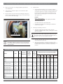
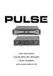
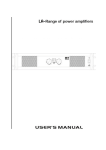
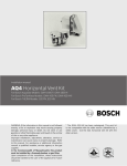
Technical Service Bulletin Low kW Electric Tankless Water Heater Troubleshooting Guide Models: AE3.4, AE7.2, AE9.5, RP1P, RP2P, RP3P, RP7P, RP9P, US3, US6, US7, US9 DANGER: ELECTRIC SHOCK ELECTRICITY IS EXTREMELY DANGEROUS. TAKE EXTRA PRECAUTIONS AND DISCONNECT THIS PRODUCT FROM THE ELECTRICAL SUPPLY BEFORE CLEANING, SERVICING OR REMOVING THE COVER. Step 1 – Document installation details DANGER: ELECTRIC SHOCK BOSCH ELECTRICAL APPLIANCES SHOULD ONLY BE SERVICED BY A TRAINED TECHNICIAN OR LICENSED ELECTRICIAN. Bosch technical support is available at 866-330-2729. Please document results from each troubleshooting step prior to calling. Without this information documented, we cannot make a determination as to what is wrong with your water heater. This will delay a resolution. Record information in Step 1 of the Building and Install questionnaire on page 5. FOR STEPS 2, 3 AND 4, SHUT OFF THE CIRCUIT BREAKER POWERING THE APPLIANCE, LOCK IT, AND VERIFY THAT THERE IS NO VOLTAGE AT THE UNIT. Step 2 – Water supply and water heater settings Verify the heater is installed in one of the two positions shown in Fig. 1. Figure 1 Installation #1 (front view) Introduction Hot Cold Who should perform the troubleshooting? Anyone who has the qualifications to work safely with 240VAC. If you do not possess the tools or the knowledge to work safely with 240VAC, contact a licensed professional. What does this troubleshooting guide cover? This guide covers every test we can advise you to perform on the location, installation, and water heater. With ALL the information from ALL the tests in this guide, it is possible to diagnose any water heater of this type to a point where we can advise a repair or cover warranty. Required tools: Adjustable wrench Empty gallon container Digital multi-meter Phillips head screwdriver Flat head screwdriver Installation #2 (front view) Hot Cold Hot Cold 2 | Troubleshooting Guide | AE3.4, AE7.2, AE9.5, RP1P, RP2P, RP3P, RP7P, RP9P, US3, US6, US7, US9 Make sure the heater is not being supplied by preheated or recirculated water. Verify that the cold water supply is connected to the INLET (marked in blue). Remove heater cover and check power setting by making sure that the Power Selection Screw (see Fig. 2) is set all the way to HI or LO and screwed down tight. Verify flow rate 1. Using a measured container (a ½ or 1 gallon container works well), time how long it takes to fill it with water from a hot water only faucet or shower. Calculate the flow rate by taking the size of the container and dividing it by the time it took then multiplying the answer by 60. This will yield a gpm result. Example: Water collected (gallons) Figure 2 Time to fill (seconds) X 60 = gallons per minute See Table 1 below for required flow rates 2. Document your findings in the Building and Installation questionnaire, page 5. Checking for plumbing crossovers: 1. Shut water supply off to the water heater using the contractor provided isolation valves, isolating the hot water side of the system. Do not turn off the water supply to the whole house; only to the water heater. If you do not have an isolation valve on the water heater, you cannot perform this test. Power selection screw NOTICE: If the Power Selector Screw is set to LO, only one of the two heating elements will operate and the output will be reduced by 50%. 2. Open ALL hot water taps connected to the water heater and set all fixtures to hot only. 3. Allow some time (approx. 5 minutes) for water to stop running and pipes to drain. If pipes are drained you should be able to place a hand over end of faucet and feel no pressure. Expected Rise in Water Temperature Model Volts Amps Table 1 Element Resistance High Setting (kW) Low Setting (kW) Temperature Rise (°F) at Flow Rate (GPM) 0.5 GPM 0.75 GPM 1.0 GPM 1.5 GPM 2.0 GPM 2.5 GPM US3, AE3.4, RP3P 120 27 2x8Ω 3.4 - 3.0 ― 41 °F 28 °F 20 °F N/A N/A N/A RP2P 277 11 1 x 25 Ω ― 3.0 41 °F 28 °F 21 °F 14 °F N/A N/A RP2P 277 22 2 x 25 Ω 6.0 ― 81 °F 55 °F 42 °F 27 °F N/A N/A US7, AE7.2, RP7P 240 15 1 x 16 Ω ― 3.6 - 3.05 N/A 32 °F 24 °F 16 °F 12 °F N/A US7, AE7.2, RP7P 240 30 2 x 16 Ω 7.2 - 6.1 ― N/A 63 °F 48 °F 32 °F 24 °F N/A US9, AE9.5, RP1P 208 18 1 x 12 Ω ― 3.5 N/A 32 °F 24 °F 16 °F 12 °F N/A US9, AE9.5, RP1P 208 35 2 x 12 Ω 7.1 ― N/A 64 °F 48 °F 32 °F 24 °F N/A US9, AE9.5, RP1P 240 20 1 x 12 Ω ― 4.75 N/A 42 °F 32 °F 21 °F 16 °F N/A US9, AE9.5, RP1P 240 40 2 x 12 Ω 9.75 ― N/A 84 °F 64 °F 42 °F 32 °F N/A RP9P 277 17.5 2 x 15.8 Ω ― 4.75 N/A 42 °F 32 °F 21 °F 16 °F N/A RP9P 277 35 1 x 15.8 Ω 9.75 ― N/A 84 °F 64 °F 42 °F 32 °F N/A Data subject to change without notice | Printed in the USA | BTC 721002307 A | 09.2013 Bosch Thermotechnology Corp. Troubleshooting Guide | AE3.4, AE7.2, AE9.5, RP1P, RP2P, RP3P, RP7P, RP9P, US3, US6, US7, US9 | 3 | 4. If any water continues to flow, you have found a crossover and one of the following conditions could exist and must be corrected: Figure 3 ― The most likely cause of this condition is that a mixing valve has an internal leak allowing cold water to mix with the hot. While this may not be causing the symptoms at your water heater, it may affect the ability of the water heater to reach temperature and can cause activation issues along with temperature fluctuations. Direction of movement ― While unlikely, a cold water pipe could be connected to a hot water pipe. If you have had some plumbing work done recently and the symptoms coincide with the work done, you may want to contact the person that did the work. 5. Close all fixtures and reopen water supply to the water heater. 6. Document your findings in the Building and Installation questionnaire, page 5. Flow switch disc Check the Thermal Cut Out: 1. Locate the thermal cut out switch (see Fig. 3). 2. Press the button located in the center of the cut out switch. If you feel it click (similar to a ball point pen), then the thermal cut out was tripped. Step 3 – Physical inspection Visual Inspection 1. 2. Figure 4 Thoroughly inspect the water heater’s internal components. Note the following: ― Any signs of melted or damaged wires ― Alignment of components ― Screw tightness ― Any signs of water leakage Document your findings in the Water Heater questionnaire, page 5. Thermal Cutout Switch Check the Flow Switch: 1. Begin with no water running through the unit. Ensure power is still off. 2. Open a faucet to allow maximum water to flow through the unit. 3. If possible, use isolation valve on cold supply to close, then open water supply to the unit. This will allow you to open and close water flow while being in front of the heater to observe. If an isolation valve is not installed, a second person will be needed to open and close the faucet, while another person is at the heater to observe the flow switch. 4. Close, then open water flow through the unit. While doing this, observe whether or not the flow switch activates. When adequate water flows through the unit the water pressure will push the flow switch disc against microswitches (see Fig. 3). You should see that movement and also hear a click. Data subject to change without notice | Printed in the USA | BTC 721002307 A | 09.2013 NOTICE: The thermal cut out trips because of another underlying problem, such as scale, low flow with warm inlet water, high temperature setting or preheated water. It is important to find the issue before returning the heater to service. 3. Document your findings in the Water Heater questionnaire, page 6. Bosch Thermotechnology Corp. 4 | Troubleshooting Guide | AE3.4, AE7.2, AE9.5, RP1P, RP2P, RP3P, RP7P, RP9P, US3, US6, US7, US9 Step 4 – Checking continuity and resistance Step 5 – Verify the power supply Check the resistance of the elements (see Fig. 5) to be sure they meet the requirements as listed in Table 1 of this document. Turn on circuit breaker supplying appliance and check the power supply using an appropriate scale. 1. Figure 5 Measure the incoming voltage across L1 and L2 terminals (see Fig. 6) to be sure the unit is receiving the correct voltage for the particular model# according to Table 1 on page 2 of this document. Copper water tubing Figure 6 Bar Two exposed element terminals 1. 2. Ensure power supply to the unit is off. Set your multimeter to Mohms (2000K, 2M or 20M). 3. Place one multimeter probe on the common steel bar that joins the two element terminals together and touch the other probe to the copper water tubing to see if you have any continuity there. 4. Document your findings in the Water Heater questionnaire, page 6. 5. Set multimeter to 100 ohms scale. While keeping one probe on the bar, use the other probe to touch each of the two exposed element terminals in turn and write down resistance readings of each. 6. Document your findings in the Water Heater questionnaire, page 6. Data subject to change without notice | Printed in the USA | BTC 721002307 A | 09.2013 L1 and L2 Incoming power terminals 2. Record your results in the Water Heater questionnaire, page 6. Bosch Thermotechnology Corp. Troubleshooting Guide | AE3.4, AE7.2, AE9.5, RP1P, RP2P, RP3P, RP7P, RP9P, US3, US6, US7, US9 | 5 | Questionnaires Building and Installation: STEP 1: Bosch Customer # (if known) Owner’s Name? Owner’s address? Owner’s phone number? Model and serial number? Model: Serial Number: Name of installer and phone number? Installer: Phone: Date of installation? Date of Installation:____/____/____ Where did you purchase this water heater? Where in the building is this water heater installed? Water supply and water pressure? Municipal Well Copper What is the water supply material to and from the heater? Plastic Stainless Flex Left Circuit breaker size and type Single pole Amperage:________ What is the gauge of the wiring supplied to the unit? _______ AWG Right Top Bottom Double pole Low High Fixture(s) used for troubleshooting this water heater? Sink Shower Flow rate of fixture(s) used for troubleshooting? _______GPM Plumbing crossover test results - crossover present? Yes Data subject to change without notice | Printed in the USA | BTC 721002307 A | 09.2013 Other:___________ If plastic, does plastic piping connect directly to unit? Yes No When facing water heater, which side of the water heater does the cold water pipe connect to? STEP 2: Temperature Power Selector Screw setting: Other:_____________________ Water pressure:_______PSI Tub All Fixtures No Bosch Thermotechnology Corp. 6 | Troubleshooting Guide | AE3.4, AE7.2, AE9.5, RP1P, RP2P, RP3P, RP7P, RP9P, US3, US6, US7, US9 Water Heater: STEP 3: Are there any burned or melted wires in the unit? Yes No Are there any signs of water leakage? Yes No Is the thermal cut out tripped? Yes No If the thermal cut out was tripped, have you reset it? Yes No Does the flow switch operate with water flow? Yes No STEP 4 : Resistance of each element Is there continuity between the bar and the copper water tubing? STEP 5: Voltage Supply: Element 1: ________ Ω Element 2: ________ Ω Yes No Voltage across L1 - L2: ________VAC After completing this questionnaire, please have your technician call us while still at the unit at 1-866-330-2729 for diagnosis and resolution or if it is more convenient, please email the completed questionnaire to ldy.asa@us.bosch.com and we will reply within one business day. Bosch Thermotechnology Corp. 50 Wentworth Avenue Londonderry, NH 03053 Tel: 1-866-330-2729 Fax: 1-603-965-7581 www.bosch-climate.us Data subject to change without notice | Printed in the USA | BTC 721002307 A | 09.2013 Bosch Thermotechnology Corp.