1
ACKNOWLEDGEMENTS
It is the policy of Drake Electronics Limited (hereafter referred to as Drake) to
continually improve the products and Drake reserves the right to modify product
specifications and characteristics without notice, at any time.
Every endeavour has been made to ensure that information, details and descriptions
set out in this literature are correct at the time of going to press. However Drake is
unable to guarantee that no changes have subsequently taken place to the
specification or characteristics of, or relating to any Drake product, after the publication
of this literature. Drake shall not be liable for any loss or damage whatsoever arising
from the use of any information, errors or omissions in this guide or any use of the
product.
E. & O.E. Correct at Time of Publication
Neither the whole, nor any part of the information contained herein, nor in the products
described in this guide, may be adapted or reproduced in any material form except with
the prior written approval of Drake.
MS-DOS and Windows 95/98 are registered trademarks of Microsoft Corporation.
Telos is a trademark of TLS Corporation.
Ethernet is a registered trademark of Xerox Corporation.
All correspondence relating to products or guides should be addressed to:
Technical Support
Drake Electronics Limited
The Hydeway
Welwyn Garden City
Hertfordshire
United Kingdom
AL7 3UQ
Tel:- +44 (0)1727 871200
Fax:- +44 (0)1707 371266
E-Mail:- techsupport@drake-uk.com
Website:- http://www.drake-uk.com
© 2000 All rights reserved.
4000 Series II - PiCo
STA0348 - Issue 2.1
Product Manual
Page i of x
DANGER
Electrical shock can cause severe personal injury or death. All
major units of this equipment are powered by mains voltage.
Unless specifically advised otherwise, DISCONNECT mains
supply before carrying out any maintenance or repair tasks.
European Union Declaration of Conformity
Drake declares that the following equipment has been manufactured in conformity with
the following standards:
BS EN 50081-1: 1992
Electromagnetic compatibility. Generic emission standard.
Residential, commercial and light industry.
BS EN 50082-1: 1998
Electromagnetic compatibility. Generic immunity standard.
Residential, commercial and light industry.
BS EN 60950: 1992
Safety of information technology equipment.
And thereby complies with the requirement of Electromagnetic Compatibility Directive
89/336/EEC and Low Voltage Directive 73/23/EEC as amended by 93/68/EEC.
Product Manual
Page ii of x
4000 Series II - PiCo
STA0348 - Issue 2.1
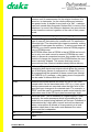
GLOSSARY OF TERMS
ADC
An Analogue to Digital Converter samples the voltage level of
an electrical input and assigns a digital value to it (a series of
1s and 0s).
ADM
Assignment, Diagnostics and Monitoring.
The CMAPSi package comprises two elements - an offline
section for configuring a Drake matrix and an online section
for real time monitoring and making 'on the fly' changes. ADM
is the online section of the package.
BNC
Standard co-axial video connector.
A type of connector used with coaxial cables such as the RG58 A/U cable used with the 10Base-2 Ethernet system. The
basic BNC connector is a male type mounted at each end of a
cable. This connector has a centre pin connected to the centre
cable conductor and a metal tube connected to the outer
cable shield. A rotating ring outside the tube locks the cable to
any female connector.
CODEC
A Coder/Decoder is a device that encodes or decodes a signal. For example, telephone companies use CODECs to convert binary signals transmitted on their digital networks to
analogue signals converted on their analogue networks.
CMAPSi
Configuration and Master Assignment Programming System
integrated is software produced by Drake Electronics, used
for configuring, controlling and monitoring their 3000, 4000
and 4000 series II range of matrices.
Conference
A facility (configured by CMAPSi), similar to older Party Line
systems.
CSU
The Central Switching Unit is the central element of the Drake
talkback system (responsible for the actual routing of audio),
the CSU is normally a 19 inch rack mounting unit. The CSU is
sometimes also referred to as the 'matrix'.
DAC
A Digital to Analogue Converter generates an output voltage
proportional to the value entered on its digital inputs (as a
series of 1s and 0s).
DAK
Direct Access Key is a Drake term used to indicate a push key
on a control panel which, when pressed, will generate an
audio route (or routes), hence providing 'direct access' to a
destination.
4000 Series II - PiCo
STA0348 - Issue 2.1
Product Manual
Page iii of x
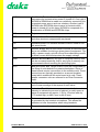
dB
The decibel (abbreviated as dB, and also as db and DB) is a
common unit of measurement for the relative loudness of a
sound or, in electronics, for the relative difference between
two power levels. A decibel is one-tenth of a “Bel”, a seldomused unit named after Alexander Graham Bell, inventor of the
telephone. In sound, the difference between two sound levels
is ten times the common logarithm of the ratio of their power
levels.
Destination port
The port used as the target port when assigning a route.
EPROM
Erasable Programmable Read-Only Memory is a special
type of memory that retains its contents until it is exposed to
ultraviolet light. The ultraviolet light clears its contents, making
it possible to reprogram the memory. To write to and erase an
EPROM, you need a special device called a PROM programmer or PROM burner.
An EPROM differs from a PROM in that a PROM can be written to only once and cannot be erased. EPROMs are used
widely in personal computers because they enable the manufacturer to change the contents of the PROM before the computer is actually shipped. This means that bugs can be
removed and new versions installed shortly before delivery.
GPI
A General Purpose Interface is a series of digital control lines,
comprising both inputs and outputs which allows the connection of third party pieces of equipment to a Drake CSU (q.v.).
By programming the operation of these control lines through
the CMAPSi (q.v.) package, a third party piece of equipment
can be made to interact with the CSU.
GPSF
A General Purpose Special Function is a set of CSU commands which can be associated with a GPI (q.v.) input, such
that the commands are executed when the logic level of the
specified input changes to the desired state. For example, a
GPSF could be used to generate an audio route between two
ports when one of the GPI input pins became logic 'high'.
Howlround
Distorted audio - due to feedback of original signal in close
proximity. An audio resonance which is generated by the
audio from an output being fed back into its input. Feedback is
characterised by a high pitch 'squeal' and can be observed
when a microphone is placed in close proximity to a loudspeaker when there is an audio route between the microphone and the loudspeaker.
I/O
Input/Output
I/P
Input
Product Manual
Page iv of x
4000 Series II - PiCo
STA0348 - Issue 2.1
IFB
Interruptable Foldback provides a caller with the ability to talk
over a normal audio feed (source) to an operator (destination).
An IFB defines matrix connections between source and destination ports while allowing IFB callers to interrupt a source
and talk to a destination.
Local
Programming
Modifying the DAK assignments via the Intelligent Control
Panel SOFT Mode
LCD
A Liquid Crystal Display is a type of display used in digital
watches and many portable computers. LCD displays utilize
two sheets of polarizing material with a liquid crystal solution
between them. An electric current passed through the liquid
causes the crystals to align so that light cannot pass through
them. Each crystal, therefore, is like a shutter, either allowing
light to pass through or blocking the light.
LED
A Light Emitting Diode is an electronic device that lights up
when electricity is passed through it.
Listen Route
An audio route to the Control Panel from a source. The audio
is normally heard on the Control Panel's Loudspeaker or
Headset.
LS
The Loudspeaker is a device that converts electrical signals
into sound waves.
MB
A MegaByte is a term used for data size: 1MB = 1,024 bytes
MHz
Megahertz is a term used to express the speed of a waveform. 1 MHz = 1 million Hertz (q.v.), or cycles per second. The
speed of microprocessors, called the clock speed, is measured in megahertz.
N/C
A Normally Closed contact is a contact that is always closed
until operated.
N/O
A Normally Open contact is a contact that is always open until
operated.
NID
A Non Intrusive Download is a means of sending new configuration information from a personal computer to a Drake CSU
while causing minimum interruption to the live operation of the
system.
4000 Series II - PiCo
STA0348 - Issue 2.1
Product Manual
Page v of x
NVRAM
Non-Volatile Random Access Memory is a type of memory
that retains its contents when power is turned off. One type of
NVRAM is SRAM that is made non-volatile by connecting it to
a constant power source such as a battery. Another type of
NVRAM uses EEPROM chips to save its contents when
power is turned off. In this case, NVRAM is composed of a
combination of SRAM and EEPROM chips.
O/P
Output
PCB
A Printed Circuit Board is a thin plate on which silicon chips
and other electronic components are placed.
Pot.
A Potentiometer is a variable resistance device used to control sound levels.
PSU
A Power Supply Unit is a unit which converts an electrical supply to one suitable for driving a given piece of equipment. Typically, a power supply unit will convert from alternating current
to direct current and will step down the supply voltage.
RAM
Random Access Memory is a type of computer memory that
can be accessed randomly; that is, any byte of memory can
be accessed without touching the preceding bytes.
RCU
Rear Connector Unit. Larger Drake CSUs are configurable by
the fitting of extra boards to a passive backplane. Some of
these boards require connections to the outside world. These
connections are typically provided on a second (smaller)
board which mates with the main board at its rear. These
smaller connector units are referred to as 'Rear Connector
Units'.
RMS
The Root Mean Squared value of a set of figures is the square
root of mean average of the square of each value.
RU
A standard Rack Unit is a measurement used in the broadcast
industry to indicate the amount of cabinet (or rack) space a
piece of equipment will require. 1 RU is 19 inches wide by
1.75 inches high (or 482.6 mm by 44.45 mm).
Side tone
Side tone is the audio, heard in the Headset earpiece, which
is generated by the headset microphone. This allows the
operators to hear themselves when using headsets.
Source port
The port used as the origin when assigning a route.
Product Manual
Page vi of x
4000 Series II - PiCo
STA0348 - Issue 2.1
TA
A Terminal Adaptor is a device that connects a computer to
an external digital communications line, such as an ISDN line.
A terminal adapter is a bit like a modem, but whereas a
modem needs to convert between analogue and digital signals, a terminal adapter only needs to pass along digital signals.
Talkback
A broadcast term referring to the intercom system.
Talk Route
An audio route from the Control Panel to another destination.
The audio is normally generated from the Control Panel's
main microphone or Headset microphone.
TBU
Telephone Balance Unit.
VOX
A Voice Operated Crosspoint is a a switch which operates
when the level of a signal passing through it rises above a certain threshold level. This threshold is normally adjustable
either electronically or mechanically, depending on the type of
switch.
XLR
Audio industry standard connector.
4000 Series II - PiCo
STA0348 - Issue 2.1
Product Manual
Page vii of x
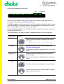
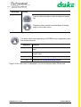
The following terms and symbols are used throughout this document:
Consult the named Drake document for further details.
Contact Drake for suitable options.
Tips given.
DANGER: Life-threatening warnings
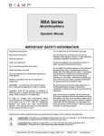
WARNINGS and CAUTIONS
Documentation Set
The following documentation is also supplied with this product:
• 4000 Series II User Guide
• 4000 Series II Installation Guide
Product Manual
Page viii of x
4000 Series II - PiCo
STA0348 - Issue 2.1
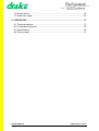
TABLE OF CONTENTS
1. INTRODUCTION .................................................................................................... 1
1.1 System Overview ............................................................................................. 1
2. GETTING STARTED ............................................................................................. 3
2.1 Unpacking The Equipment ............................................................................... 3
2.2 Installation ........................................................................................................ 3
3. MATRIX DESCRIPTION ........................................................................................ 5
3.1 Overview .......................................................................................................... 5
3.2 Matrix Front Panel Description ......................................................................... 5
3.3 Matrix Rear Panel Description ......................................................................... 9
4. COMMISSIONING ............................................................................................... 13
4.1 Front screen ................................................................................................... 13
4.2 Map Software ................................................................................................. 14
5. OPERATION ........................................................................................................ 19
5.1 Overview ........................................................................................................
5.2 Main menu .....................................................................................................
5.3 Map select screen ..........................................................................................
5.4 Remote Audio ................................................................................................
5.5 Remote Key ...................................................................................................
5.6 Input Levels ....................................................................................................
5.7 Output Levels .................................................................................................
5.8 Passcode .......................................................................................................
5.9 Status .............................................................................................................
5.10 Security ........................................................................................................
19
20
21
23
27
32
34
39
43
44
6. ADVANCED CONFIGURATION ......................................................................... 53
6.1 CMAPSi ......................................................................................................... 53
7. SYSTEM EXPANSION ........................................................................................ 55
7.1 Panels ............................................................................................................
7.2 Other matrices ...............................................................................................
7.3 ISDN equipment .............................................................................................
7.4 Telephone hybrids .........................................................................................
4000 Series II - PiCo
STA0348 - Issue 2.1
55
55
55
55
Product Manual
Page ix of x
7.5 Router panels ................................................................................................. 55
7.6 Supervisor panel ............................................................................................ 55
8. APPENDICES ...................................................................................................... 57
8.1 Technical settings ..........................................................................................
8.2 Troubleshooting guide ...................................................................................
8.3 Specifications .................................................................................................
8.4 Factory maps .................................................................................................
Product Manual
Page x of x
57
58
60
61
4000 Series II - PiCo
STA0348 - Issue 2.1
1. INTRODUCTION
1.1 System Overview
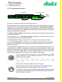
The 4000 Series II Pico is a 32 port, (optionally expandible to 36 ports), 1RU compact
matrix using a microprocessor controlled digital audio switcher for routing calls and
audio between outstations connected in a star format. A front-mounted control service
and display provide the user with matrix configuration tools and the ability to select from
6 internal Maps without the use of a PC.
The PiCo digital audio switching matrix uses a microprocessor for control and
configuration purposes. A digital router section, allowing multiple routes to be made
simultaneously, provides all switching, level control and routing. Analogue audio, GPI
inputs and outputs, data interfaces and connections to CMAPSi configuration software
package, (optional), are also provided as part the PiCo system. An optional 4 port
beltpack audio expansion card is available for ring circuits or audio trunk lines.
The full range of 4000 series II control panels is available providing a suitable user
interface for making and receiving calls over the system. These panels have push
buttons configured to operate specific audio routes and/or activate GPI control
functions. Several callers can speak to the same destination at the same time due to
the mixing capability of the matrix.
The key actions are sent as data using a serial link over Category 5 cable to the central
matrix for interpretation by the microprocessor and information is returned to the control
panel by the same method. Analogue audio is also sent and received via the same
standard CAT5 cable, allowing easy connection to patch-fields for over-plugging or
monitoring.
The crosspoints in the PiCo matrix are activated or de-activated according to
configuration rules held in the system's current Map, (stored in the microprocessor's
memory). The PiCo can store 6 Maps in its memory for quick selection via the front user
controls. Other system Maps can be downloaded into the Matrix from a PC with the
'Configuration and Master Assignment Programming System - integrated' configuration
software, (CMAPSi) and controls every aspect of 4000 PiCo series operation including
a comprehensive diagnostic facility, ADM, (optional). The Matrix sends part of the
system map out to each control panel, programming the actions available on each DAK
of each panel.
PiCo matrix destinations and sources can be other panels, beltpacks, 2-wire, (via
suitable interfaces), or 4-wire circuits, either individually or in groups. The destinations
and sources could also be in another remote talkback system. Connection to other
3000 or 4000 Series matrix systems is either achieved by use of Ethernet, (optional),
or through the Drake VeNiX ISDN system, providing an integrated private intercom
network.
4000 Series II - PiCo
STA0348 - Issue 2.1
Product Manual
Page 1 of 66
Contact Drake for details on 4 port expansion, CMAPSi, ADM, Ethernet or ISDN networking.
CMAPSi operation details are given in CMAPSi on-line help.
Product Manual
Page 2 of 66
4000 Series II - PiCo
STA0348 - Issue 2.1
2. GETTING STARTED
2.1 Unpacking The Equipment
The Pico matrix is tested prior to dispatch to ensure correct operation and should be
inspected for damage during transit. Any damage should be reported to Drake or their
appointed representative.
2.2 Installation
2.2.1 General Information
It is necessary to have sufficient space at the front and the rear of the equipment bay
holding the matrix to allow ease of access during installation.
It is also assumed that the correct cables and cable lengths have been determined for
the installation of the control panels and externals. It is advisable to have all cable runs
completed prior to fitting the system into the equipment bays.
Note: In order to comply with EMC requirements, screened CAT5 cable should be
used for all system cabling.
The physical and electrical requirements for each part of the system are detailed in this
guide.
CAUTION.
It is recommended that the rear of the matrix is supported
following installation in the apparatus cabinet.
DANGER
Risk of electrical shock. All installation operations must be
completed before applying mains AC power to the system.
Suitably qualified personnel conversant with current electrical
safety requirements should perform the installation.
Ensure that the AC supply to the digital routing matrix matches
that required by the power supply units installed (the maximum
power rating is marked on the rear of each matrix).
4000 Series II - PiCo
STA0348 - Issue 2.1
Product Manual
Page 3 of 66
The internal power supplies are capable of auto sensing voltages in the ranges 100120V and 200-240V. Voltages outside these ranges must not be attached to the unit.
Forced air cooling via internal fans is provided to maintain the unit at the correct
operating temperatures. Inadequate or obstructed ventilation may result in serious
damage to the system.
CAUTION.
Adequate ventilation must be provided to avoid serious
overheating of the module components.
Contact Drake sales for details on additional cooling equipment.
2.2.2 Installing the Pico matrix
Installation should be carried out in the following order:
1. Prepare the cables for the matrix as described in the 4000 Series II Installation
Guide.
2. Remove the covers from the ear mountings.
3. Install the Pico matrix into the equipment rack.
4. Refit the covers from the ear mountings.
5. Connect all the cables to the matrix.
6. Switch on the power and check that the matrix front panel display illuminates.
7. If the system requires programming, connect a PC to the matrix.
Note: The PC to Matrix connection should be made using the cable supplied by Drake
with the Matrix.
Product Manual
Page 4 of 66
4000 Series II - PiCo
STA0348 - Issue 2.1
3. MATRIX DESCRIPTION
3.1 Overview
The Pico matrix comprises a 1U by 19 inch rack mount unit with connections being
made from both the front and rear of the frame. The Matrix power supply is provided by
internally fitted PSUs, connected via IEC connectors to the mains supply.
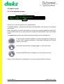
3.2 Matrix Front Panel Description
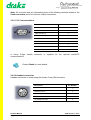
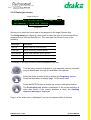
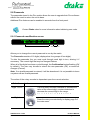
3.2.1 Front View
ENTER
button
Connections
and facilities
Rack mounting
cover
Rotary encoder
LCD display
Rack mounting
cover
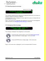
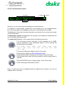
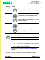
3.2.2 Connections and Facilities
PC data link
(9-way D-type connector)
System
reset button
Headset
connector
4000 Series II - PiCo
STA0348 - Issue 2.1
Product Manual
Page 5 of 66
Note: All connector and pin information given in the following sections relates to the
fixed connectors and not to the free (cable) connectors.
3.2.2.1 PC Communications
Description
5
9
1
6
Pin Number
-
1
Data receive (Rx)
2
Data transmit (Tx)
3
-
4
Screen
5
-
6
-
7
-
8
-
9
A 9-way D-type female connector is supplied for the optional matrix/PC
communications.
Contact Drake for more details.
3.2.2.2 Headset connection
Headset connection is made using the female 5-way DIN connector.
Description
1
3
5
2
Product Manual
Page 6 of 66
4
Pin Number
-
1
Headphone return
2
Right headphone output
3
-
4
Left headphone output
5
4000 Series II - PiCo
STA0348 - Issue 2.1
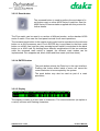
3.2.2.3 Reset button
The recessed button is used to perform the equivalent of a
red button reset on other 4000 Series II matrices. See the
4000 Series II Documentation supplied with this product for
further details.
The Pico matrix can be reset in a number of different modes, as the standard 4000
series II matrix. Pico uses the front panel controls for all reset operations.
The recessed reset button is the master reset control and is equivalent to the red reset
button on a 4642 processor card. Pico's ENTER key is equivalent to the blue mode
button on a 4642 card, and the rotary encoder's push switch is equivalent to the black
button on a 4642 card. By holding down different combinations of the two switches
while the recessed reset switch is tapped, the different reset modes can be
implemented. Pico supports red, black, black and blue resets (not blue alone).
3.2.2.4 ENTER button
The push button acts as the Enter key in the user interface.
Pushing this button whilst inside a menu will cause the
current selection to be accepted by the system.
The push button may also be used as part of a reset
procedure.
3.2.2.5 Display
&XUUHQW#PDS=61WHUWLXVF#6\V#38#+OWK=2.##s
3QO=
The display is made up of two rows of characters. The current selection (an option or
a value) is shown with flashing characters.
4000 Series II - PiCo
STA0348 - Issue 2.1
Product Manual
Page 7 of 66
3.2.2.6 Rotary encoder
The rotary encoder is positioned to the right of the
illuminated display, and is used for:
• Screen navigation
• Selection of various options
Turning the rotary encoder changes the current menu
selection. The current selection is displayed in flashing text.
If the current menu page has no selection options, turning
the encoder will have no effect.
The rotary encoder operates on a one click per transition
basis in either clockwise or counter-clockwise directions.
The rotary encoder includes a built-in switch that has two basic functions:
Pressing the rotary encoder has two separate effects:
• If the switch is pressed briefly (less than one second), the
action is interpreted as an undo request. In most cases the
display will move one level backwards in the menu - the
position occupied before the press button was last used.
• If the switch is pressed and held in (more than one second), the display will return to one of the Main Menu pages,
regardless of the current location within the menu structure.
Product Manual
Page 8 of 66
4000 Series II - PiCo
STA0348 - Issue 2.1
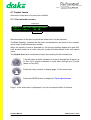
3.3 Matrix Rear Panel Description
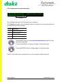
3.3.1 Rear View
IEC Mains
Connectors
Expansion slot for Universal Audio interface
PC Data Link (9-way D-type connector)
GPI Interface (25-way
D-type connector)
Audio and data ports (RJ45 sockets)
Ethernet (RJ45 socket)
3.3.2 Connections and Facilities
3.3.2.1 Earthing Point
The mains earth is connected to the Pico chassis via a stud mounted behind the mains
IEC connectors. No external earthing points are supplied.
3.3.2.2 IEC Mains Inlet
Two IEC mains inlets are provided. Connect both of these inlets for correct redundant
power operation.
3.3.2.3 Ethernet
Ethernet connection is provided by a single RJ45 connector.
Description
4000 Series II - PiCo
STA0348 - Issue 2.1
Pin Number
Data Transmit (TD+)
1
Data Transmit (TD-)
2
Data Receive (RD+)
3
-
4
-
5
Data Receive (RD-)
6
-
7
-
8
Product Manual
Page 9 of 66
3.3.2.4 GPI Interface
The General Purpose Interface (GPI) provides 8 opto-isolated inputs and 8 outputs, 4
of which are relay contact closures and the remaining 4 are open-collector.
Non-isolated GPI controls may be achieved by connecting an input pin to the matrix
ground (pin 13) to turn on the GPI input (see below).
Opto-isolated inputs may be achieved by changing the jumper link LK3 from pins 1-2
(non-isolated) to pins 2-3 (isolated), and then applying a supply voltage of 7V to 24V at
60mA max. between pin 24 (+ve) and pin 12 (-ve). Connecting the input pin to pin 12
triggers the input. See “Technical settings” on page 57.
Relay-isolated outputs provide normally open contacts with a maximum current
capacity of 1A. Each open collector output offers a switched technical 0V sink capable
of powering up to a 50mA load.
The first GPI output connection (pin 1) is reserved as the PSU Fail indicator. The GPI
output is deactivated when a failure of either PSU is detected.
Description
Pin Number
Relay Output 1 N/C
1
Relay Output 1 P
14
Relay Output 1 N/O
2
Relay Output 2 P
15
Relay Output 2 N/O
3
Relay Output 3 P
16
Relay Output 3 N/O
4
Relay Output 4 P
17
Relay Output 4 N/O
5
Direct DC Control Output 5
18
SOCKET
(FE M A L E )
Direct DC Control Output 6
6
(V IE W F R OM FR O N T)
Direct DC Control Output 7
19
Direct DC Control Output 8
7
GPI Input 1
20
GPI Input 2
8
GPI Input 3
21
GPI Input 4
9
GPI Input 5
22
GPI Input 6
10
GPI Input 7
23
GPI Input 8
11
1
14
25
13
Product Manual
Page 10 of 66
4000 Series II - PiCo
STA0348 - Issue 2.1
Description
Pin Number
Isolated Inputs (requires external +V applied)
24
Isolated Inputs (requires external -V applied)
12
+5v
25
Ground
13
P
P ole (C om m o n)
N /C N orm a lly C lose d
N /O N o rm ally O pe n
D irect D C C on trol O u tpu t
3.3.2.5 Audio and Data Connection
32-channel serial communications are provided using an RS422 interface.
Description
Pin Number
Data Receive (Rx+)
1
Data Receive (Rx-)
2
Audio Input (+)
3
Audio Output (+)
4
Audio Output (-)
5
Audio Input (-)
6
Data Transmit (Tx+)
7
Data Transmit (Tx-)
8
3.3.2.6 Matrix Power Supply
Two power supply units are fitted as standard providing power and redundancy
operation.
.
Specification:
110/240V auto-selecting, switched mode, 60 watt.
5V @ 8A, +12V @ 3A, -12V @ 0.5A
4000 Series II - PiCo
STA0348 - Issue 2.1
Product Manual
Page 11 of 66
Product Manual
Page 12 of 66
4000 Series II - PiCo
STA0348 - Issue 2.1
4. COMMISSIONING
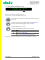
4.1 Front screen
The front screen is displayed when the Pico unit is powered up or reset.
Company
name
Product name
#######'UDNH##7333#VHULHV#,,##3LFR
##########&XUUHQW#PDS#=510DS#QDPH
Current map
The front screen displays the company name, product name and name of the currently
active map.
The Current map number (1 to 6) and map name (factory-set) is displayed.
If the map is empty or invalid, this field displays <No map>.
Press the rotary encoder to display the first page of the main menu.
The Diagnostics screen is displayed if you do not respond within 2 minutes.
4000 Series II - PiCo
STA0348 - Issue 2.1
Product Manual
Page 13 of 66
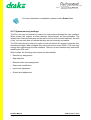
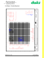
4.2 Map Software
4.2.1 Introduction
Pico can store up to six standard maps at any one time. Only one of these maps may
be 'active' at once.
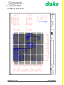
Five factory default maps are provided with Pico. The following diagram shows the
initial states of the six map numbers.
See also, map details in Appendix 1.
Map 1
Map 2
Map 3
Map 4
Map 5
Map 6
Factory
default map
Factory
default map
Factory
default map
Factory
default map
Factory
default map
Drake test
map
STUDIO
STUDIOS
NEWS
OB-MAP
ATC SIM
Overwritable
Overwritable
Overwritable
Overwritable
Overwritable
Read only
4.2.2 Changing the active map
Pico defaults to the last map number when powered-up. The currently active map may
only be changed via the user interface.
Changing the currently active map from the user interface will always instigate a red
reset (see supplied 4000 Series II documentation for details on matrix resets).
The user cannot select an invalid, empty or corrupted map. If Pico is reset with an
empty or corrupted map, the display will indicate that the map is invalid and no menu
options relating to the current map will be accessible.
4.2.3 Downloading maps
The CMAPSi option may be used to download other maps.
Contact Drake for details on CMAPSi.
Maps downloaded from CMAPSi to Pico carry the map number to which they are
directed. For more information on downloading maps, see CMAPSi help.
Some important points:
• When a map is downloaded from CMAPSi, the user may select whether or not to
instigate a reset at the matrix.
• If a new map is downloaded to a map number other than the currently active map
number, the existing map is immediately overwritten (i.e.: the map number is filled
with the new map).
Product Manual
Page 14 of 66
4000 Series II - PiCo
STA0348 - Issue 2.1
• If a map is downloaded to the currently active map number, the new map is stored
in a temporary area until a reset is carried out, at which point the in-use map is
overwritten.
4.2.4 VOXes
A VOX (Voice Operated Switch) is a switch which is automatically turned on when the
audio level of the port with which it is associated rises above a certain threshold level.
The Pico matrix has VOXes associated with all 32 of its standard ports and with the 4
universal audio ports (if the option is fitted). The threshold level of every VOX is fixed
at -20 dBU and the VOXes are not used in the factory default maps.
For more information on configuring VOXes for custom maps, please
contact Drake Sales.
4.2.5 Tone injection facility
The Pico unit has an inbuilt tone injector. This generates a sine wave at a frequency of
1KHz and at a level of 0dBU. Neither the amplitude nor frequency of this signal may be
altered. Whilst this port is not directly accessible from the user interface, it behaves as
a normal port and may have routes made from it (for instance, via a PC connected to
the Pico matrix).
The tone inject output is assigned port number 637.
The level monitor input is assigned port 637.
4.2.6 Level monitor facility
The Pico unit has an inbuilt level monitoring port. This port measures the level of a
signal routed to it, in dBU. This level may be read by the Pico software. Whilst this port
is not directly accessible from the user interface, it behaves as a normal port and may
have routes made to it (for instance, via a PC connected to the Pico matrix).
The headset socket and the level monitor output are wired in parallel; any audio routed
to the level monitor will automatically be heard on a headset connected to the headset
socket.
CAUTION.
Ensure that the headset volume is set to a low level to avoid
acoustic shock.
Care should be taken when manually making routes to the level
monitor input as this could cause inaccurate level readings to be
indicated at the display.
4000 Series II - PiCo
STA0348 - Issue 2.1
Product Manual
Page 15 of 66
For more information on headsets, please contact Drake Sales.
4.2.7 System security settings
The Pico unit may be 'locked' by means of a code entered through the user interface.
When locked, the majority of menu features (listed below) are not accessible. The
locked menu features are shown on the main menu (in their normal locations), but with
a 'key' icon on each side to indicate that they are not currently accessible.
The PIN code which is entered in order to lock and unlock the system comprises four
hexadecimal digits. When shipped, the code is set to four zeros ('0000'). The user may
change this code through the user interface. There is no user interface-only method for
resetting the PIN code.
When locked, the following menu items are inaccessible:
• Remote key assignment
• Map selection
• Remote audio route assignment
• Pass code modification
• Input level adjustment
• Output level adjustment.
Product Manual
Page 16 of 66
4000 Series II - PiCo
STA0348 - Issue 2.1
4.2.8 Dynamic level assignments
The input and output levels for Pico ports are adjustable through the user interface.
These adjustments are carried out dynamically.
In the level adjustment pages for each of these settings, the rotary encoder is turned in
order to select a new level. The newly selected level will not become effective until the
rotary encoder has not been moved for a period of 0.5 seconds.
Important conditions:
• If the level is confirmed, the newly selected level is retained.
• If an exit is performed by (a.) tapping the rotary encoder, (b.) holding down the
rotary encoder for a period of greater than one second or (c.) the inactivity timeout,
the original level setting will be automatically reinstated.
• If an exit is performed by any other means (e.g.: a download is instigated, or unit
power is removed), the last level which was set within the state (by means of the
rotary encoder having been turned and then left for 0.5 seconds) will remain active.
4.2.9 PIN code
In the event of the current PIN code being lost, the factory default may be restored by
performing a reset with the grey button held down (this is located internally).
4000 Series II - PiCo
STA0348 - Issue 2.1
Product Manual
Page 17 of 66
Product Manual
Page 18 of 66
4000 Series II - PiCo
STA0348 - Issue 2.1
5. OPERATION
5.1 Overview
You may navigate around the Pico facilities using the main menu.
Following a reset (or system power up) the Map Select screen is displayed. In all other
cases, the previously highlighted menu option is retained by the system.
5.1.1 Menu structure
Main menu 1
Y
Map select
Map
number?
Confirm?
Remote audio
Source
port?
Destination
port?
Route
type?
Remote key
Target
panel?
Target
key?
Route
type?
Input levels
Port
number?
Level?
Output level
Port
number?
Tone
inject?
Passcode
Modification?
Feature
list
Status
Status
S YSTEM
RESET
Confirm?
Destination
port?
Y
Level?
Next
Main menu 2
Previous
Security
settings
Security
4000 Series II - PiCo
STA0348 - Issue 2.1
PIN entry?
Lock/Unlock
Security
settings?
Confirm?
Change PIN
Modify
PIN?
Confirm?
Product Manual
Page 19 of 66
5.2 Main menu
The main menu consist of two screens, page 1 and page 2. You may change between
them by selecting the Next or Previous option, as appropriate.
Key symbol
Option
Key symbol
##0DS#VHOHFW##5HPRWH#DXGLR##5HPRWH#NH\
#,QSXW#OHYHOV#2XWSXW#OHYHO#####1H[W
Page 1
Next option
Previous option
###3UHYLRXV######3DVVFRGH######6WDWXV
###6HFXULW\
Page 2
The current item on the menu flashes. If the currently selected item is locked (see
“Security” on page 44), a key symbol appears on either side of the flashing text.
Turn the rotary encoder clockwise to move to the next option; counterclockwise to move to the previous option.
If the current option is Next, then page 2 is displayed; if the current
option is Previous, page 1 is displayed.
Press the ENTER button to select the highlighted option (if unlocked).
If you do not respond within 30 seconds, the front page is displayed.
Product Manual
Page 20 of 66
4000 Series II - PiCo
STA0348 - Issue 2.1
5.3 Map select screen
Default mapnames 1 to 3
0DSV#4=0DSQDPH4##5=0DSQDPH5##6=0DSQDPH6
#####7=0DSQDPH7##8=0DSQDPH8##9=0DSQDPH9
Default mapnames 4 to 6
Allows you to change the currently active map. When a map is selected (even if the
same map was previously active), the system will reset.
The map names are specified during creation in CMAPSi. The name of the currently
selected map flashes.
If there is no map, or the map is invalid, the map name is displays <No map> and can
not be selected.
Turn the rotary encoder clockwise to select the next map number (up
to Map 6); counter-clockwise to select the previous map number (down
to Map 1).
Press the rotary encoder to display page 1 of the main menu.
Press the ENTER button to display the Confirmation screen (if the
selected map is valid).
Page 1 of the main menu is displayed if you do not respond within 2 minutes.
4000 Series II - PiCo
STA0348 - Issue 2.1
Product Manual
Page 21 of 66
5.3.1 Confirmation screen
##$UH#\RX#VXUH#WKDW#\RX#ZLVK#WR#VHOHFW
PDS#¶0DSQDPH8·#DQG#UHVHW#WKH#PDWUL["#1R
Allows you to confirm that you wish to select the indicated map and reset the matrix.
The default is No. Select Yes if you wish to select the new map.
Turn the rotary encoder clockwise to select Yes; counter-clockwise to
select No.
Press briefly to display the Map select screen.
Press and hold down to display page 1 of the main menu.
Press the ENTER button to finish.
The action taken is dependant upon the current selection:
Selection
Actions
Yes
Activates the selected map and causes a red reset
No
Displays the Map select screen.
Page 1 of the main menu is displayed if you do not respond within 2 minutes.
Product Manual
Page 22 of 66
4000 Series II - PiCo
STA0348 - Issue 2.1
5.4 Remote Audio
A source port, destination port, and a route type must be specified in order to set a route
assignment for remote audio.
5.4.1 Source port screen
Source port
#6RXUFH#SRUW#=#943#9LVLRQ#PL[HU
Allows you to set the source port of the route assignment.
The Source port (flashing), displays the dial code and description (stored in the
currently active map).
When the system is reset or powered up, the first port number (600) is displayed.
Until another power up or reset, the port number defaults to the last viewed port.
Turn the rotary encoder clockwise to cycle up through the 32 ports (up
to port 631); counter-clockwise to cycle down through the 32 ports
(down to port 600).
Press the rotary encoder to display page 1 of the main menu.
Press the ENTER button to accept the current source port selection.
The Destination port screen is then displayed
.
Page 1 of the main menu is displayed if you do not respond within 2 minutes.
4000 Series II - PiCo
STA0348 - Issue 2.1
Product Manual
Page 23 of 66
5.4.2 Destination port screen
Destination port
#'HVWLQDWLRQ#SRUW#=#933#3RUW'HVFULSWLRQ
#&XUUHQW#URXWH#=#1RQH
Current route
Allows you to set the destination port of the route assignment.
The Destination port (flashing), displays the dial code and description (stored in the
currently active map).
When the system is reset or powered up, the first port number (600) is displayed.
Until another power up or reset, the port number defaults to the last viewed port.
The Current route indicates the current route type between the specified source and
destination ports.
The route type for this assignment is set in the Route type screen.
Turn the rotary encoder clockwise to cycle up through the 32 ports (up
to port 631); counter-clockwise to cycle down through the 32 ports
(down to port 600).
Press the rotary encoder briefly to display the Source port screen.
Press and hold down to display page 1 of the main menu.
Press the ENTER button to accept the current destination port
selection and displays the Route type screen.
Page 1 of the main menu is displayed if you do not respond within 2 minutes.
Product Manual
Page 24 of 66
4000 Series II - PiCo
STA0348 - Issue 2.1
5.4.3 Route type screen
Source port
Destination port
943#9LVLRQ#PL[HU###?!933#3RUW'HVFULSWLRQ
5RXWH#W\SH#=#1RQH
Route type
Allows you to set the route type for this assignment.
The Route type indicates the current route setting for this assignment:
Route type
Description
None
No actions relating to these crosspoints
Talk and listen
Source and destination port talk to each other
Listen only
Source port listens to destination port
Talk only
Source port talk to destination port
Turn the rotary encoder clockwise to cycle up through the available
route types to None; counter-clockwise to cycle down through the
available route types to Talk only.
Press the rotary encoder briefly to display the Destination port
screen.
Press and hold down to display page 1 of the main menu.
Press the ENTER button to store the new assignment. Page one of the
main menu is then displayed
If the assignment is rejected (for example, the assignment limit for the
system has been reached), the Action request failed message is
displayed.
Page 1 of the main menu is displayed if you do not respond within 2 minutes.
4000 Series II - PiCo
STA0348 - Issue 2.1
Product Manual
Page 25 of 66
5.4.4 Action request failed message
########8QDEOH#WR#DVVLJQ#DFWLRQ
###########3OHDVH#SUHVV#HQWHU
This message is displayed if an assignment was submitted but rejected (for example,
the assignment limit for the system has been reached).
Press the rotary encoder briefly to display the Route type screen.
Press and hold down to display page 1 of the main menu.
Press ENTER button to return to page one of the main menu.
Page 1 of the main menu is displayed if you do not respond within 2 minutes.
Product Manual
Page 26 of 66
4000 Series II - PiCo
STA0348 - Issue 2.1
5.5 Remote Key
5.5.1 Target panel screen
Target panel port
#3RUW#=#933#3RUW'HVFULSWLRQ
#5HPRWH#NH\V##3DQHO#WRWDO=337#8QXVHG=336
Panel total
Unused
Allows you to assign routes to keys on panels which have been set to Remote Key.
The Port (flashing), displays the dial code and description (as stored in the currently
active map) of the selected port number. Only ports which are assigned as panels with
at least one Remote Key qualify for the list of valid ports.
After a reset or power-up, the default port will be the first panel port (from port 0) with
at least one Remote Key. At all other times, the default port will be the last viewed port.
The Panel total value is the number of keys on the selected panel which are set as
Remote Keys.
The Unused value is the number of keys on the selected panel which are set as
Remote Keys, and do not currently have a route assigned to them.
Turn the rotary encoder clockwise to cycle upwards; counter-clockwise
to cycle downwards, through all panels which have at least a single
Remote Key assignment.
Press the rotary encoder to display page 1 of the main menu.
Press the ENTER button to accept the current port selection. The
Target key screen screen is then displayed.
Page 1 of the main menu is displayed if you do not respond within 2 minutes.
4000 Series II - PiCo
STA0348 - Issue 2.1
Product Manual
Page 27 of 66
5.5.2 Target key screen
Target panel port
Key
#3RUW#=#943#9LVLRQ#PL[HU#####.H\#=#347
#$VVLJQPHQW=#933#3RUW'HVFULSWLRQ#7DON
Assignment
Allows you to select the key to which a route is to be assigned.
The target Key number (flashing), is the number of the key to which a route is to be
assigned. Only key numbers which are assigned as Remote Keys will be shown. The
default value for this field is always the first Remote Key on the target panel (counting
from zero).
The Assignment name contains the dial code and description (as stored in the
currently active map) of the port number to which the current route on the selected
Remote Key is assigned. If the currently selected Remote Key does not carry an
assignment, None is displayed.
The type assigned to the selected Remote Key is also displayed, which may be one of
the following:
Route type
Description
Talk
A talk only route is assigned to this key
Listen
A listen only route is assigned to this key
Tlk+Lsn
A talk and listen route is assigned to this key
T+FL
A talk and forced listen route is assigned to this key
None
No route is currently assigned to this key
Turn the rotary encoder clockwise to cycle upwards; counter-clockwise
to cycle downwards, through all keys which are assigned as Remote
Keys on the target panel.
Press the rotary encoder briefly to display the Target panel screen.
Press and hold down to display page 1 of the main menu.
Press the ENTER button to accepts the selected target key. The Route
type screen is then displayed.
Page 1 of the main menu is displayed if you do not respond within 2 minutes.
Product Manual
Page 28 of 66
4000 Series II - PiCo
STA0348 - Issue 2.1
5.5.3 Route type screen
Target panel port
Key
#3RUW#=#943#9LVLRQ#PL[HU#####.H\#=#347
#$VVLJQPHQW=#7DON#DQG#OLVWHQ
Assignment
Allows you to select the route type to be assigned to the target Remote Key.
The Assignment type (flashing), allows you to select the type of route which will be
assigned to the selected Remote Key. The route type may be set to one of the
following:
Route type
Description
Talk only
Assign a talk only route to this key
Listen only
Assign a listen only route to this key
Talk and listen
Assign a talk and listen route to this key
Talk+forced lsn
Assign a talk and forced listen route to this key
None
Cancel any existing routes on this key
The default is the type of route currently assigned to the key.
Turn the rotary encoder clockwise to cycle upwards; counter-clockwise
to cycle downwards, through the available route options.
Press the rotary encoder briefly to display the Target key screen.
Press and hold down to display page 1 of the main menu.
Press the ENTER button to accept the current route type selection.
The Destination port screen is displayed (if the current selection is
other than None). If the current selection is None, the Awaiting
response message is displayed.
Page 1 of the main menu is displayed if you do not respond within 2 minutes.
4000 Series II - PiCo
STA0348 - Issue 2.1
Product Manual
Page 29 of 66
5.5.4 Destination port screen
Target panel port
Key
#3RUW#=#943#9LVLRQ#PL[HU#####.H\#=#347
#7DON#DQG#OLVWHQ#WR#933#3RUW'HVFULSWLRQ
Assignment
Destination port
Allows you to select the port to which a route will be made when the Remote Key is
pressed.
The Destination port (flashing), displays the port number and description currently
selected.
Turn the rotary encoder clockwise to cycle up through the 32 ports (up
to port 631); counter-clockwise to cycle down through the 32 ports
(down to 600).
Press the rotary encoder briefly to display the Route type screen.
Press and hold down to display page 1 of the main menu.
Press the ENTER button to accept the current route type selection.
The Awaiting response message is then displayed.
Page 1 of the main menu is displayed if you do not respond within 2 minutes.
Product Manual
Page 30 of 66
4000 Series II - PiCo
STA0348 - Issue 2.1
5.5.5 Awaiting response message
Beating heart symbol
#####$WWHPSWLQJ#WR#DVVLJQ#UHPRWH#NH\###s
###############3OHDVH#ZDLW
This message is displayed when attempting to assign the Remote Key. All controls are
inoperative while this message is displayed.
A beating heart symbol is displayed in the top right of the screen to indicate that the
main processor is running.
Page 1 of the main menu is displayed if the assignment is successful. If the assignment
was unsuccessful, the Assignment failed message is displayed.
5.5.6 Assignment failed message
#######8QDEOH#WR#DVVLJQ#UHPRWH#NH\
###########3OHDVH#SUHVV#HQWHU
This message is displayed if the assignment is unsuccessful.
Press the rotary encoder briefly to return to the Route type screen.
Press and hold down to display page 1 of the main menu.
Press the ENTER button to display page 1 of the main menu.
Page 1 of the main menu is displayed if you do not respond within 2 minutes.
4000 Series II - PiCo
STA0348 - Issue 2.1
Product Manual
Page 31 of 66
5.6 Input Levels
5.6.1 Port selection screen
Input port
#3RUW#=#933#3RUW'HVFULSWLRQ
#,QSXW#OHYHO#=#043G%
Input level
Allows you to set the input level of a selected port.
The Port (flashing), contains the dial code and description (as stored in the currently
active map).
When the system is reset or powered up, the first port number displayed is port 600.
Until another power up or reset, the port number will then default to the last viewed
value.
The Input level contains the current input level setting for the selected port.
Turn the rotary encoder clockwise to cycle up through the 32 ports (up
to Port 631); counter-clockwise to cycle down through the 32 ports
(down to Port 600).
Press the rotary encoder to display page 1 of the main menu.
Press the ENTER button to display the Level selection screen.
Page 1 of the main menu is displayed if you do not respond within 2 minutes.
Product Manual
Page 32 of 66
4000 Series II - PiCo
STA0348 - Issue 2.1
5.6.2 Level selection screen
Input port
Loudspeaker symbol
#3RUW#=#933#3RUW'HVFULSWLRQ
#,QSXW#OHYHO#=#043G%
Input level
Allows you to set a new input level setting for the selected port.
A crosspoint is automatically created from the selected port to the headset/monitor
port. The output gain of the headset monitor port is automatically set to 0dB.
The Port name is the dial code and description (as stored in the currently active map)
of the selected port.
A loudspeaker symbol is displayed at the top right of the display to indicate that the
unit is currently monitoring audio.
The Input level (flashing), is the current input level setting for the port.
Turn the rotary encoder clockwise to cycle upwards (up to 18dB);
counter-clockwise to cycle downwards (down to CUT), through the
following input level stages:
CUT -60dB -48dB -36dB
-12dB -9dB -6dB -3dB
15dB 18dB
-30dB -24dB -18dB -15dB
0dB 3dB 6dB 9dB 12dB
The new level becomes effective after 0.5 seconds.
Press briefly to display the Port selection screen.
Press and hold down to display the first page of the main menu.
In both these cases, audio monitoring ceases, and the original level is
restored.
Press the ENTER button to display page 1 of the main menu.
Audio monitoring automatically ceases.
Page 1 of the main menu is displayed and the original level restored, if you do not
respond within 2 minutes.
4000 Series II - PiCo
STA0348 - Issue 2.1
Product Manual
Page 33 of 66
5.7 Output Levels
Allows the output level of a port to be modified.
5.7.1 Port selection screen
Output port
#3RUW#=#933#3RUW'HVFULSWLRQ
#2XWSXW#OHYHO#=#.33#G%
Output level
Allows selection of the port for which the output level is to be adjusted.
The Port (flashing), contains the dial code and description (as stored in the currently
active map) of the selected port number.
When the system is reset or powered up, the first port number displayed is port 600.
Until another power up or reset, the port number will then default to the last viewed
value.
The Output level value contains the output level setting for the selected port.
Turn the rotary encoder clockwise to cycle up through the 32 ports (up
to Port 631); counter-clockwise to cycle down through the 32 ports
(down to Port 600).
Press the rotary encoder to display page 1 of the main menu.
Press the ENTER button to display the Tone inject screen.
Page 1 of the main menu is displayed if you do not respond within 2 minutes.
Product Manual
Page 34 of 66
4000 Series II - PiCo
STA0348 - Issue 2.1
5.7.2 Tone inject screen
Output port
Tone
setting
#3RUW#=#933#3RUW'HVFULSWLRQ##7RQH=2II
#2XWSXW#OHYHO#=#.33#G%
Output level
Allows you to inject a constant 1kHz sine wave into the output port, if desired.
The Port setting displays the dial code and description (as stored in the currently active
map) of the selected port number.
The Tone setting allows you to inject a constant tone into the port. The tone will only
be injected if confirmed (see Tone injection confirmation screen) and will only
remain present for the duration of Level selection screen. The default state for this
selection is always Off, and may be turned On using the rotary encoder.
The Output level value contains the current output level setting for the port.
Turn the rotary encoder clockwise to switch the tone On; counterclockwise to switch the tone Off.
Press briefly to display the Port selection screen.
Press and hold down to display page 1 of the main menu.
Press the ENTER button to finish.
The action taken is dependant upon the current selection:
Selection
ENTER button
Tone Off
Displays the Level selection screen.
Tone On
Displays the Tone injection confirmation screen.
Page 1 of the main menu is displayed if you do not respond within 2 minutes.
4000 Series II - PiCo
STA0348 - Issue 2.1
Product Manual
Page 35 of 66
5.7.3 Tone injection confirmation screen
#######$UH#\RX#VXUH#WKDW#\RX#ZLVK
##########WR#LQMHFW#WRQH#"#1R
Confirmation
Allows you to confirm that you wish to inject tone.
You may select Yes or No. The default setting is No.
Turn the rotary encoder clockwise to answer Yes; counter-clockwise to
answer No.
Press the rotary encoder briefly to display the Tone inject screen.
Press and hold down to display page 1 of the main menu.
Press the ENTER button to finish.
The action taken is dependant upon the current selection:
Selection
Actions
No
Displays the Tone inject screen.
Yes
Injects the tone (the Tone symbol is displayed in the top right of the
screen). The Level selection screen is then displayed.
Page 1 of the main menu is displayed if you do not respond within 2 minutes.
Product Manual
Page 36 of 66
4000 Series II - PiCo
STA0348 - Issue 2.1
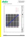
5.7.4 Level selection screen
Tone inject symbol
Output port
#3RUW#=#933#3RUW'HVFULSWLRQ
#2XWSXW#OHYHO#=#.4;#G%#####_#########_
Output level
Audio
monitor
symbol
Audio monitor
Allows you to select an output level setting for the port.
Any ports routed to the output port are automatically routed to the headset/monitor port.
The gain level of each copied crosspoint is also duplicated. A loudspeaker symbol is
displayed at the top right of the display to indicate that the unit is currently monitoring
audio. The audio gain of the headset/monitor output port is copied from the current gain
setting of the selected output port.
An Audio monitor symbol is displayed to indicate that the selected output has been
routed to the headset.
If tone injection is on, a Tone inject symbol is displayed to indicate that the tone is
currently injected into the selected output port.
The Output level (flashing), displays the current output level setting for the port.
A real time Audio monitor (in the form of a bar graph) is displayed in the lower right
hand corner of the display. This indicates the current audio level at the audio level
monitor output port.
The 0dBu point is displayed as a colon (:). When the level falls below this point, it is
represented as a series of solid blocks. When the level rises above this point, those
parts of the graph beyond the 0dBu point are represented as hollow blocks. If the graph
reaches (or covers) the 0dBu colon, the colon will be inverted. The nine blocks of the
level monitor correspond to levels from -15 to +9 dBu in 3 dBu steps.
Turn the rotary encoder clockwise to cycle upwards (up to 18dB);
counter-clockwise to cycle downwards (down to CUT), through the
following input gain stages:
CUT -60dB -48dB -36dB
-12dB -9dB -6dB -3dB
15dB 18dB
-30dB -24dB -18dB -15dB
0dB 3dB 6dB 9dB 12dB
The new level becomes effective after 0.5 seconds.
Press the rotary encoder briefly to display the Tone inject screen.
Press and hold down to display page 1 of the main menu.
In both these cases, audio monitoring automatically ceases and the
output gain of the headset/monitor port is automatically set to 0dB. The
old level setting is restored.
4000 Series II - PiCo
STA0348 - Issue 2.1
Product Manual
Page 37 of 66
Press the ENTER button to display page 1 of the main menu. Audio
monitoring automatically ceases and the output gain of the headset/
monitor port is automatically set to 0dB.
Page 1 of the main menu is displayed if you do not respond within 2 minutes. Audio
monitoring automatically ceases and the output gain of the headset/monitor port is
automatically set to 0dB. The old level setting is restored.
Product Manual
Page 38 of 66
4000 Series II - PiCo
STA0348 - Issue 2.1
5.8 Passcode
The passcode stored in the Pico matrix allows the user to upgrade their Pico software
without the need to return the unit to base.
Additional Pico features can be enabled in seconds from the front panel.
Contact Drake sales for more information about obtaining new code.
5.8.1 Passcode modification screen
#######3OHDVH#HQWHU#QHZ#SDVVFRGH#=
ýýý]34560789:0;<$%0&'()]]###2.
########ýýý]
ýýý]
Passcode
Confirmation
Allows you to change the current passcode in use by the matrix.
The Passcode consists of 16 digits (displayed as four groups of four digits).
To alter the passcode, the you must cycle through each digit in turn, altering it if
necessary. The current digit that may be changed flashes.
When all of the digits have been cycled through, the Confirmation begins flashing (OK
by default). The user may choose to submit the new passcode (OK), or cancel all
changes (Cancel).
Note: If an invalid passcode is entered, it will be abandoned. It is not possible to leave
a system with an invalid passcode.
The action of the rotary encoder is dependant upon the current selection:
Selection
Actions
Digits 1 to 16
Turn the rotary encoder clockwise to increase the
value of the current digit; counter-clockwise to
decrease the current digit in the range:
0 1 2 3 4 5 6 7 8 9 A B C D E F
Digit 1
Press the rotary encoder briefly to display page 2 of
the main menu.
4000 Series II - PiCo
STA0348 - Issue 2.1
Product Manual
Page 39 of 66
Selection
Actions
Digits 2 to 16
Press the rotary encoder briefly to return to the previous digit of the passcode
OK
Turn the rotary encoder clockwise to set Cancel.
Press the rotary encoder briefly to return to the last
digit of the passcode
Cancel
Turn the rotary encoder counter-clockwise to set
OK.
Press the rotary encoder briefly to return to the last
digit of the passcode.
Press the rotary encoder and hold down to display
page 2 of the main menu.
Pressing the ENTER button is dependant upon the current selection:
Selection
Digits 1 to 15
Actions
Accepts the current digit, and steps to the next digit
Digit 16
The OK confirmation becomes the current field and begins flashing.
OK
The new passcode is submitted, and (if accepted), is written into
flash memory (this may take a few seconds). The Passcode
accepted message is then displayed.
Cancel
Displays the page 2 of the main menu.
If the passcode is rejected, the Passcode rejected message is
displayed.
Page 2 of the main menu is displayed if you do not respond within 2 minutes.
Product Manual
Page 40 of 66
4000 Series II - PiCo
STA0348 - Issue 2.1
5.8.2 Passcode rejected message
############3DVVFRGH#UHMHFWHG
############3OHDVH#SUHVV#HQWHU
This message is displayed if the new passcode is rejected.
Press the rotary encoder briefly to return to the Passcode
modification screen.
Press and hold down to display the page 2 of the main menu.
Press the ENTER button to display page 2 of the main menu.
Page 2 of the main menu is displayed if you do not respond within 2 minutes.
4000 Series II - PiCo
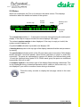
STA0348 - Issue 2.1
Product Manual
Page 41 of 66
5.8.3 Passcode accepted message
#3DVVFRGH#DFFHSWHG#0#3OHDVH#SUHVV#HQWHU
)HDWXUHV=HWK#3/#VSY#3
Features
This message appears if the new passcode is accepted.
The Features contains a list of firmware features enabled by the new passcode and
are defined in the following table:
Feature
Description
eth 0
No Ethernet support
eth 1
Ethernet support
spv 0
No supervisor panel support
spv 1
Supervisor panel support
Press briefly to return to the Passcode modification screen. The new
passcode is retained.
Press and hold down to display the page 2 of the main menu.
Press the ENTER button to display page 2 of the main menu.
Page 2 of the main menu is displayed if you do not respond within 2 minutes.
Product Manual
Page 42 of 66
4000 Series II - PiCo
STA0348 - Issue 2.1
5.9 Status
When left unattended, the Pico unit reverts to the status screen. This displays
information about the health and status of the system.
Current map
System
number
Health
Beating heart
symbol
&XUUHQW#PDS=410DS#QDPH#6\V#34#+OWK=2.##s
3QO=########0########0########0
Panel status
Computer
symbol
The current map number (1 - 6) and name cannot be changed using the matrix panel
display. If the map is empty or invalid, the name displays <No map>.
The network system number is also displayed. If the map is empty or invalid, the
system number displays XX.
A system health indication is provided, and displays OK.
A beating heart symbol in the top right of the display indicates that the main processor
is running.
The panel status indicates which of the 32 ports has a panel connected. Solid display
blocks represent connected panels; hollow blocks represent no panel or audio-only
connection. The ports are represented in groups of 8 blocks; the leftmost being ports
1-8 and the rightmost being ports 25-32. Within each group the ports are numbered
sequentially from left to right.
A computer symbol in the bottom right of the display flashes during a download. This
is only displayed during a download operation and is visible on this screen only - it is
not displayed if you switch to another screen during a download.
Press the rotary encoder to display the last page visited in the main
menu.
4000 Series II - PiCo
STA0348 - Issue 2.1
Product Manual
Page 43 of 66
5.10 Security
Allows you to lock and unlock access to the following features:
• Remote key assignment
• Map selection
• Remote audio route assignment
• Pass code modification
• Input level adjustment
• Output level adjustment.
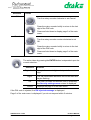
5.10.1 PIN entry screen
PIN
Confirmation
#3OHDVH#HQWHU#3,1#QXPEHU#=#033330#2.
You must enter the existing PIN before security features can be modified.
The PIN displays the code entered by the user, and defaults to 0000. The current digit
flashes. You can submit or cancel the new PIN code, by setting the confirmation The
default is OK.
The action taken by the rotary encoder is dependant upon the current selection:
Selection
Digits 1 to 4
Actions
Turn the rotary encoder clockwise to increase the
value of the current digit; counter-clockwise to
decrease the current digit in the range:
0 1 2 3 4 5 6 7 8 9 A B C D E F
Digit 1
Press the rotary encoder briefly to display page 2 of
the main menu.
Press and hold down to display page 2 of the main
menu.
Digits 2 to 4
Press the rotary encoder briefly to return to the
previous digit of the PIN code.
Press and hold down to display page 2 of the main
menu.
Product Manual
Page 44 of 66
4000 Series II - PiCo
STA0348 - Issue 2.1
Selection
Actions
OK
Turn the rotary encoder clockwise to set Cancel.
Press the rotary encoder briefly to return to the last
digit of the PIN code.
Press and hold down to display page 2 of the main
menu.
Cancel
Turn the rotary encoder counter-clockwise to set
OK.
Press the rotary encoder briefly to return to the last
digit of the PIN code.
Press and hold down to display page 2 of the main
menu.
The action taken by pressing the ENTER button is dependant upon the
current selection:
Selection
Digits 1 to 3
Actions
Accepts the current digit, and steps to the next
digit.
Digit 4
The OK confirmation becomes the current field and
begins flashing.
OK
The new PIN code is submitted, and (if accepted),
the Security settings menu screen is displayed.
Cancel
Displays the page 2 of the main menu.
If the PIN code is rejected, the PIN rejected message is displayed.
Page 2 of the main menu is displayed if you do not respond within 2 minutes.
4000 Series II - PiCo
STA0348 - Issue 2.1
Product Manual
Page 45 of 66
5.10.2 PIN rejected message
############3,1#FRGH#UHMHFWHG
############3OHDVH#SUHVV#HQWHU
This message is displayed if the PIN is incorrect.
Press the rotary encoder briefly to return to the PIN entry screen.
Press and hold down to display page 2 of the main menu.
Press the ENTER button to display page 2 of the main menu.
Page 2 of the main menu is displayed if you do not respond within 2 minutes.
Product Manual
Page 46 of 66
4000 Series II - PiCo
STA0348 - Issue 2.1
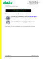
5.10.3 Security settings menu
Lock/unlock option
Change PIN option
#/RFN28QORFN##&KDQJH#3,1
############
This menu provides options to lock or unlock the Pico user interface, or change the
current PIN number.
The Lock/Unlock option allows you to change the access status for the Pico matrix.
When unlocked, all menu options are accessible; when locked, only the front screen,
diagnostics screen and PIN code entry screens may be accessed.
The Change PIN option allows you to change the current four digit PIN that is required
to access the security settings menu.
Turn the rotary encoder clockwise to select Change PIN; counterclockwise to select Lock/Unlock.
Press the rotary encoder briefly to return to the PIN entry screen.
Press and hold down to display page 2 of the main menu
Press the ENTER button to select the option and display the
appropriate screen.
Page 2 of the main menu is displayed if you do not respond within 2 minutes.
4000 Series II - PiCo
STA0348 - Issue 2.1
Product Manual
Page 47 of 66
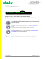
5.10.4 Security status screen
Security
status
#6HW#VHFXULW\#VWDWXV#=#/RFNHG
############
Allows you to lock or unlock access to the Pico matrix settings.
The Security status Indicates whether the system security status is Locked or
Unlocked.
Turn the rotary encoder clockwise to select Locked; counter-clockwise
to select Unlocked.
Press the rotary encoder briefly to return to the Security settings
menu.
Press and hold down to display page 2 of the main menu.
Press the ENTER button to accept the setting. The Access status
confirmation screen is then displayed.
Page 2 of the main menu is displayed if you do not respond within 30 seconds.
Product Manual
Page 48 of 66
4000 Series II - PiCo
STA0348 - Issue 2.1
5.10.5 Access status confirmation
Confirmation
#8QORFN#V\VWHP#"#&RQILUP
############
Allows you to confirm the new security status
The Confirmation status (flashing) displays Cancel (default) or Confirm.
Turn the rotary encoder clockwise to select Cancel; counter-clockwise
to select Confirm.
Press the rotary encoder briefly to return to the Security status
screen.
Press and hold down to display page 2 of the main menu.
The action taken by pressing the ENTER button is dependant upon the
current selection:
Selection
Actions
Confirm
Applies the new security status, then displays page
2 of the main menu.
Cancel
Displays the Security status screen.
Page 2 of the main menu is displayed if you do not respond within 30 seconds.
4000 Series II - PiCo
STA0348 - Issue 2.1
Product Manual
Page 49 of 66
5.10.6 PIN modification screen
PIN
Confirmation
#3OHDVH#HQWHU#QHZ#3,1#QR1=#033330#2.
############
Allows you to change the PIN - the four digit code required to gain access to the
security features menu (see PIN entry screen).
The PIN displays the code entered by the user. The default state of this field is always
four zeroes ('0000'): for security reasons, the display does not default to the current
PIN. As each digit is entered, the active digit flashes.
The Confirmation flashes, after the PIN has been entered. You can then choose to
submit or cancel the PIN.
The action taken by the rotary encoder is dependant upon the current selection:
Selection
Digits 1 to 4
Digit 1
Actions
Turn the rotary encoder clockwise to increase the
value; counter-clockwise to decrease the value in
the range:
0 1 2 3 4 5 6 7 8 9 A B C D E F
Press the rotary encoder briefly to display the
Security settings menu.
Press and hold down to display page 2 of the main
menu.
Digits 2 to 4
Press the rotary encoder briefly to move to the
previous digit
Press and hold down to display page 2 of the main
menu.
OK
Turn the rotary encoder clockwise to select Cancel
Press the rotary encoder and hold down to display
page 2 of the main menu.
Product Manual
Page 50 of 66
4000 Series II - PiCo
STA0348 - Issue 2.1
Selection
Actions
Cancel
Turn the rotary encoder counter-clockwise to select
OK.
Press the rotary encoder and hold down to display
page 2 of the main menu.
The action taken when pressing the ENTER button is dependant upon
the current selection:
Selection
Actions
Digits 1 to 3
Accepts the current value and steps on to the next
digit
Digit 4
Accepts the current value and moves to the confirmation field
Cancel
Displays the Security settings menu.
OK
Displays the PIN confirmation screen.
Page 2 of the main menu is displayed if you do not respond within 30 seconds.
4000 Series II - PiCo
STA0348 - Issue 2.1
Product Manual
Page 51 of 66
5.10.7 PIN confirmation screen
New PIN
Confirmation
#&KDQJH#3,1#QXPEHU#WR#¶4567·#"#&RQILUP
###########
Allows you to confirm or cancel the new PIN.
The Confirmation (flashing), allows you to Confirm or Cancel the new PIN.
Turn the rotary encoder clockwise to select Cancel (default); counterclockwise to select Confirm.
Press the rotary encoder briefly to return to the PIN confirmation
screen.
Press and hold down to display page 2 of the main menu.
The action taken when pressing the ENTER button is dependant upon
the current selection:
Selection
Actions
Confirm
The new PIN is permanently stored in the system,
replacing any previous PIN. Page 2 of the main
menu is then displayed
Cancel
The PIN entry screen screen is redisplayed.
Page 2 of the main menu is displayed if you do not respond within 30 seconds.
Product Manual
Page 52 of 66
4000 Series II - PiCo
STA0348 - Issue 2.1
6. ADVANCED CONFIGURATION
6.1 CMAPSi
The Pico matrix connects to a PC running the CMAPSi package via a serial or ethernet
link. Only versions of CMAPSi supporting Pico matrices can be used. Older versions
will behave unpredictably and should not be used.
Pico is programmed using the standard 4000 Series II programming standards. Further
information on CMAPSi may be found in the Help text.
Contact Drake Sales for more details on CMAPSi.
6.1.1 Map generation and editing
6.1.1.1 Map generation
Maps destined for a Pico matrix are created and edited using the CMAPS package, as
for other Drake matrices. The limit of 32 physical ports should be reflected in any maps
used for a Pico matrix. Maps which do not accurately reflect the hardware settings of
the Pico matrix will not be rejected upon download, but will cause either errors to be
generated, or certain elements of the map to be inaccessible. The rules for these errors
/ limits are identical to those for a standard 4000 system with a map which does not
reflect the matrix's hardware.
6.1.2 ADM
6.1.2.1 General ADM compatibility
The Pico user interface has the access rights of an ADM with local privileges.
Router panels and PCs running ADM may be attached to the Pico matrix - the standard
rules for interaction between router panels and ADMs apply.
ADM may be used to perform online assignments and monitoring of the PICO system
as in the standard 4000 Series II equipment range. Further information may be found
in the ADM Help text.
6.1.2.2 Hardware monitor
The ADM hardware monitor can be configured to display a Pico mimic. This is achieved
by modifying the settings in the 'FrameType' section of the 'ADPMAIN.INI' file. The
appropriate system number should be set to a value of '5', for each Pico system.
The Pico mimic in the ADM hardware monitor shows a single 1U unit with a more
conventional passive backplane matrix below, indicating the Pico hardware
equivalency. The state of these ‘virtual cards’ shown in the Pico hardware equivalent
reflect the state of the internal Pico subsystems. The colour scheme used to indicate
error status is identical to that used for all other matrix types within ADM.
4000 Series II - PiCo
STA0348 - Issue 2.1
Product Manual
Page 53 of 66
The hardware monitor provided on the Pico user interface and the hardware monitor
provided within ADM are entirely separate entities, which do not communicate with
each other. Clearing the errors in one will not cause the reported error state in the other
to change.
All reported subsystem errors will also prompt an error message to be displayed on the
screen. The error messages which can be reported are as follows:
Error in subsystem
Error message
CODEC (slot 3)
Lower range CODEC is faulty
CODEC (slot 4)
Mid range CODEC is faulty
CODEC (slot 5)
Upper range CODEC is faulty
SCRCU (slot 3)
Lower range serial communications subsystem is faulty
SCRCU (slot 4)
Upper range serial communications subsystem is faulty
GPIRCU
General purpose input / output subsystem is faulty
FRM
Audio routing subsystem is faulty
Product Manual
Page 54 of 66
4000 Series II - PiCo
STA0348 - Issue 2.1
7. SYSTEM EXPANSION
7.1 Panels
Any Drake panel (standard, or otherwise) with a CAT-5 HDLC connection is compatible
with the Pico matrix.
7.2 Other matrices
Networking of Pico matrices is supported as per standard 4000 series II inter-system
networking. It is possible to connect a Pico matrix to (a) other Pico matrices, (b) 4000
series I matrices, (c) 4000 series II matrices and (d) 3000 series matrices.
7.3 ISDN equipment
The Pico unit may be connected to Drake Venix units. The support provided for these
connections is as for standard 4000 series II matrices.
7.4 Telephone hybrids
The connection of TELOS units to the Pico matrix is supported by connection of
interface cable PD4009. This special cable is required to allow connection of this unit
to the Pico matrix.
Pico does not support incoming call routing via pin numbering for Telos units.
7.5 Router panels
A router panel is a special control panel which connects to a standard panel port and
provides the user with extra system control functionality. An operator can remotely
configure routes between ports, assign remote keys and adjust port input and output
levels using the router panel.
Router panels and PCs running ADM may be attached to the Pico matrix - the standard
rules for interaction between router panels and ADMs apply.
7.6 Supervisor panel
A Supervisor panel is a special type of control panel which can 'share' control with
another panel on the system. This allows a system supervisor to oversee and interact
with the operation of a second control panel from a remote location.-
Contact Drake Sales for details on the range of expansion equipment
designed to supplement the Pico matrix.
4000 Series II - PiCo
STA0348 - Issue 2.1
Product Manual
Page 55 of 66
Product Manual
Page 56 of 66
4000 Series II - PiCo
STA0348 - Issue 2.1
8. APPENDICES
8.1 Technical settings
8.1.1 Links
Jumper links LK12 and LK13 are used to enable/disable power fail detection of each
supply.
8.1.2 PSU fail indicator
ADM also supports this option. Contact Drake for further details
8.1.3 Tone injection
The tone inject output is assigned port number 637.
8.1.4 Level monitor
The level monitor input is assigned port 637.
8.1.5 PIN code
In the event of the current PIN code being lost, the factory default may be restored by
performing a reset with the grey button held down (this is located internally).
4000 Series II - PiCo
STA0348 - Issue 2.1
Product Manual
Page 57 of 66
8.2 Troubleshooting guide
The following troubleshooting guide offers a few procedures to overcome common
problems encountered. Please read this guide before reporting errors to Drake.
FRONT DISPLAY NOT WORKING, PANELS DISPLAY 'WAITING FOR DATA' MESSAGE
1. Check IEC mains cable is plugged into the IEC socket on the rear of the unit. If is
fault still present proceed to 2.
2. Check that the other end of the cable is plugged into a suitable, working mains outlet which is switched on. If is fault still present proceed to 3.
3. Replace the mains cable with a known working mains cable. If is fault still present
proceed to 4.
4. Plug the mains cable into a known working power socket. If fault is still present the
Pico matrix is faulty and should be returned to Drake for repair.
PANELS DO NOT DISPLAY ANY KEY DESIGNATIONS
1. Check that the system is running a valid map. If is fault still present proceed to 2.
2. Check that the panels are connected to the correct ports. If is fault still present proceed to 2.
3. Load Map 6 as current system map. If is fault still present Pico matrix is faulty and
should be returned to Drake for repair.
PANEL DISPLAYS 'WAITING FOR DATA' MESSAGE
1. Check that a correctly wired CAT5 cable is plugged in to the rear of the panel and
that the other end of the cable is connected to a port on the Pico matrix which has
been configured for panel operation. If is fault still present move to test 2.
2. Replace panel with a known working unit. If fault is still present move to 3 if the fault
is rectified then the original panel is faulty and should be returned to Drake for
repair.
3. With the faulty panel reconnected move the cable at the matrix end to a known
working port. If the fault is still present the cable is faulty and should be replaced. If
the fault is rectified then the port on the Pico is faulty and the matrix should be
returned to Drake for repair.
Product Manual
Page 58 of 66
4000 Series II - PiCo
STA0348 - Issue 2.1
NO AUDIO TO AND/OR FROM THE PANEL
1. Check that a correctly wired CAT5 cable is plugged in to the rear of the panel and
that the other end of the cable is connected to a port on the Pico matrix which has
been configured for panel operation. If is fault still present move to test 2.
2. Replace panel with a known working unit. If fault is still present move to 3 if the fault
is rectified then the original panel is faulty and should be returned to Drake for
repair.
3. With the faulty panel reconnected move the cable at the matrix end to a known
working port. If the fault is still present the cable is faulty and should be replaced. If
the fault is rectified then the port on the Pico is faulty and the matrix should be
returned to Drake for repair.
4000 Series II - PiCo
STA0348 - Issue 2.1
Product Manual
Page 59 of 66
8.3 Specifications
Dimensions:
482mm (19 inches) wide
43.6mm (1.72 inches) high
485mm (19.5 inches) deep
Weight:
5.3 Kg
Power requirements:
110v to 250v, 50/60Hz, 60W max.
Frequency response:
20Hz to 22KHz ±0.5dB
Crosstalk (adjacent channel):
< -80dBu @ 20KHz
Nominal level:
0dBu
Matrix headroom:
+18dBu
Distortion:
< 0.03% @ 0dBu @ 1KHz
Off noise:
73dBu @ 20Hz to 22KHz
On noise:
71dBu @ 20Hz to 22KHz
Input impedance:
> 10KΩ
Input balance:
Output impedance:
200Ω @ 20Hz
Output balance:
< -30dBu
Linearity:
±1dB
AC power inputs/outputs:
2 x IEC AC inputs (500mA)
Product Manual
Page 60 of 66
4000 Series II - PiCo
STA0348 - Issue 2.1
8.4 Factory maps
The following Factory Default Map Matrix drawings are provided:
Map 1 - Single Studio
Map 2 - Dual Studio
Map 3 - News
Map 4 - Outside Broadcast
Map 5 - see note 1
Map 6 - Engineering Test
Note 1: Map 5 is a simulation Air Traffic Control map and contains many special
logic functions that cannot be adequately described by a matrix map diagram
alone. For this reason, Map 5 is not included in this appendix.
For more information, contact Simulation & Defence at Drake Electronics Sales.
4000 Series II - PiCo
STA0348 - Issue 2.1
Product Manual
Page 61 of 66
Product Manual
Page 62 of 66
PORT 2
PORT 3
PORT 4
PORT 5
PORT 6
STUDIO PA
SOUND
VISION
LIGHTING
GRAPHICS
PORT 23
PORT 24
PORT 25
PORT 26
PORT 27
PORT 28
PORT 29
PORT 30
PORT 31
PORT 32
4-WIRE 7
4-WIRE 8
4-WIRE 9
4-WIRE 10
4-WIRE 11
4-WIRE 12
4-WIRE 13
4-WIRE 14
4-WIRE 15
4-WIRE 16
DO
NOT SCALE
PORT 22
4-WIRE 6
This drawing/specification is the property of
DRAKE ELECTRONICS LIMITED
and may not be reproduced or disclosed
to a third party in any form without the
written permission of the company
3rd ANGLE
BP PORT 36
BP PORT 35
BP PORT 34
BP PORT 33
PORT 21
4-WIRE 5
PORT 16
SPARE
PORT 20
PORT 15
SPARE
PORT 19
PORT 14
SPARE
4-WIRE 4
PORT 13
SPARE
4-WIRE 3
PORT 12
SPARE
PORT 18
PORT 11
SPARE
PORT 17
PORT 10
SPARE
4-WIRE 2
PORT 9
SPARE
4-WIRE 1
PORT 8
MCR
TECHNICIAN
PORT 7
PORT 1
DIRECTOR
All dimensions are in mm
unless otherwise stated.
Normal tolerances stated;
No decimal place; +or-1,0mm
1 decimal place; +or-0,3mm
2 decimal places; +or-0,1mm
Unless otherwise stated.
A3
F
E
D
C
B
A
2
A
ISS
30-11-99
DATE
CAMERA 4
CAMERA 3
CAMERA 2
CAMERA 1
REMOTE 3
REMOTE 2
REMOTE 1
EXTERNAL 3
EXTERNAL 2
EXTERNAL 1
4215
4215
4215
4215
4215
4224
4215
4224 MASTER
IDEAL PANEL
TYPE
DIRECTOR
WRS
3
SOUND
PCN
GRAPHICS
EA
INIT.
4
EXTERNAL 1
SPARE
SPARE
DESCRIPTION
5
IFBs
REMOTE 1
1
6
4-WIRE 15
4-WIRE 14
4-WIRE 13
4-WIRE 12
MAN. APPROVED
ENG. APPROVED
CADD CHECKED
4-WIRE 16
4-WIRE 11
EXTERNAL 3
SPARE
4-WIRE GRP T/L
4-WIRE GRP T/L
4-WIRE GRP T/L
4-WIRE GRP T/L
IFB X 3
IFB X 3
IFB X 3
IFB X 3
IFB X 3
IFB X 3
INTERCOM
INTERCOM
INTERCOM
INTERCOM
INTERCOM
INTERCOM
32 KEY + DISPLAY
16 KEYS
16 KEYS
16 KEYS
16 KEYS
16 KEYS
4-WIRE GRP T/L
10
(01727) 871200
(01707) 371266
(01707) 391312
TITLE
PART No
MATRIX BLOCK DIAGRAM
4000 SERIES II PICO TALKBACK
SINGLE STUDIO MAP 2
MAP2
30-NOV-99
A
ISSUE
NOT
NotTO
Scaled
SCALE
DRG.No.
DATE
SCALE
GROUP LISTEN ONLY
GROUP TALK ONLY
ISOLATED TALK
INTERUPTABLE CLOSED
NORMALLY CLOSED
LISTEN ONLY
TALK ONLY
CROSSPOINT TYPES
2) VISION ENG HAS KEY (PTC) TO SWITCH CAMERAS TO LISTEN TO PTB
1) DIR & PA HAVE AN OPEN MIC FOR PRODUCTION TALK-BACK
MAP NOTES
4-WIRE GRP T/L
IFB X 3
INTERCOM
4-WIRE GRP T/L
4-WIRE GRP T/L
IFB X 3
INTERCOM
STATION FEATURES
9
32 KEY + DISPLAY
8
16 KEYS
DRAKE ELECTRONICS LTD.
S.J. Simpson
EA
The Hydeway
Telephone:
Welwyn Garden City
Fax:
Herts AL7 3UQ U.K.
Hot line:
E-Mail: DrakeElectronics@Compuserve.com
DRAWN BY
7
8.4.1 Map 1 - Single Studio
4000 Series II - PiCo
STA0348 - Issue 2.1
CAMERA 4
CAMERA 3
CAMERA 2
CAMERA 1
REMOTE 3
REMOTE 2
EXTERNAL 2
SPARE
SPARE
SPARE
SPARE
MCR
TECHNICIAN
SPARE
LIGHTING
VISION
STUDIO PA
PORT 3
PORT 4
PORT 5
PORT 6
ST 1 VISION
ST 1 SOUND
ST 1 CCU OP
ST 1 GFX
PORT 28
PORT 29
PORT 30
PORT 31
PORT 32
4-WIRE 12
4-WIRE 13 CF-1
4-WIRE 14 CF-2
4-WIRE 15 CF-3
4-WIRE 16 CF-4
DO
NOT SCALE
This drawing/specification is the property of
DRAKE ELECTRONICS LIMITED
and may not be reproduced or disclosed
to a third party in any form without the
written permission of the company
3rd ANGLE
BP PORT 36
PORT 27
4-WIRE 11
BP PORT 35
PORT 26
4-WIRE 10
ST 2 TECH.
PORT 25
4-WIRE 9 (TELE)
ST 2 FLOOR MAN.
PORT 24
MAINTENANCE
BP PORT 34
PORT 23
ST 2 TECH MANAGER
BP PORT 33
PORT 22
ST 2 GFX
ST1 TECH
PORT 21
ST 1 FLOOR MAN.
PORT 20
PORT 16
4-WIRE 8 IFB4
ST 2 CCU OP
PORT 15
4-WIRE 7 IFB3
ST 2 SOUND
PORT 14
4-WIRE 6 IFB2
PORT 19
PORT 13
4-WIRE 5 IFB1
ST 2 VISION
PORT 12
4-WIRE 4
ST 2 ASSISTANT
PORT 11
4-WIRE 3
PORT 18
PORT 10
4-WIRE 2
PORT 17
PORT 9
4-W1 (PGM/STD LS.)
ST 2 PRODUCER
PORT 8
ST 1 TECH MANAGER
CAR
All dimensions are in mm
unless otherwise stated.
Normal tolerances stated;
No decimal place; +or-1,0mm
1 decimal place; +or-0,3mm
2 decimal places; +or-0,1mm
Unless otherwise stated.
A3
F
E
D
C
B
PORT 2
PORT 7
PORT 1
A
ISS
1-10-99
DATE
BPS1010
BPS1010
BPS1010
BPS1010
4215
4215
4215
4215
4215
4215
4215
4224 MASTER
4215
4215
4215
4215
4215
4215
4215
4224 MASTER
ST 1 PRODUCER
WRS
ST 1 VISION
PCN
ST 1 GFX
sab
INIT.
IFBs
4-WIRE 3
ST 1 ASSISTANT
ST 2 PRODUCER
DESCRIPTION
5
4
4
5
5
4
4
5
5
4
4
5
5
4
4
5
4-WIRE 5 IFB1
ST 1 PRODUCER
4-WIRE 4
IDEAL PANEL
4-WIRE 7 IFB3
4-WIRE 6 IFB2
TYPE
4
4-WIRE 8 IFB4
A
3
5
6
4
4
5
5
4-WIRE 12
MAN. APPROVED
ENG. APPROVED
CADD CHECKED
4
4
4
4
5
5
4
4
4
5
5
4-WIRE 14 CF-2
4-WIRE 13 CF-1
2
CAM. ISOs
4-WIRE 15 CF-3
4000 Series II - PiCo
STA0348 - Issue 2.1
4
4
4
5
5
ST 1 FLOOR MAN.
7
ST 2 FLOOR MAN.
ST1 TECH
4-WIRE 11
ST 2 VISION
4-WIRE GRP T/L
4-WIRE GRP T/L
4-WIRE GRP T/L
4-WIRE GRP T/L
IFB X 4
IFB X 4
IFB X 4
IFB X 4
INTERCOM
INTERCOM
INTERCOM
INTERCOM
INTERCOM
16 KEYS
16 KEYS
16 KEYS
16 KEYS
16 KEYS
PART No
(01727) 871200
(01707) 371266
(01707) 391312
TITLE
MATRIX BLOCK DIAGRAM
BP TALK
MAP1
1-OCT-99
A
ISSUE
NOT
NotTO
Scaled
SCALE
DRG.No.
DATE
SCALE
GROUP LISTEN ONLY
GROUP TALK ONLY
ISOLATED TALK
INTERUPTABLE CLOSED
NORMALLY CLOSED
LISTEN ONLY
TALK ONLY
CROSSPOINT TYPES
4000 SERIES II PICO TALKBACK
TWO STUDIO MAP
INTERCOM
16 KEYS
4-WIRE GRP T/L
BP TALK
INTERCOM
16 KEYS
BP TALK
4-WIRE GRP T/L
INTERCOM
4-WIRE GRP T/L
16 KEYS
BP TALK
4-WIRE GRP T/L
INTERCOM
16 KEYS
INTERCOM
16 KEYS
BP TALK
BP TALK
BP TALK
BP TALK
BP TALK
BP TALK
BP TALK
BP TALK
BP TALK
10
4-WIRE GRP T/L
INTERCOM
16 KEYS
16 KEYS
CAMERA ISO X4
INTERCOM IFB X 4
4-WIRE SEPERATE TALK AND LISTEN
INTERCOM ISO X 4
4-WIRE GRP T/L
IFB X 4
INTERCOM
16 KEYS
32+32 SHIFT KEYS
4-WIRE GRP T/L
IFB X 4
CAMERA ISO X4
INTERCOM IFB X 4
4-WIRE SEPERATE TALK AND LISTEN
STATION FEATURES
9
INTERCOM
32 KEY + DISPLAY
8
16 KEYS
DRAKE ELECTRONICS LTD.
S.J. Simpson
SAB
ST 2 TECH.
The Hydeway
Telephone:
Welwyn Garden City
Fax:
Herts AL7 3UQ U.K.
Hot line:
E-Mail: DrakeElectronics@Compuserve.com
DRAWN BY
4-WIRE 16 CF-4
1
8.4.2 Map 2 - Dual Studio
Product Manual
Page 63 of 66
4-WIRE 10
MAINTENANCE
ST 2 TECH MANAGER
4-WIRE 9
ST 2 GFX
ST 2 CCU OP
ST 2 SOUND
ST 2 ASSISTANT
4-WIRE 2
4-WIRE 1
ST 1 TECH MANAGER
CAR
ST 1 CCU OP
ST 1 SOUND
ST 1 ASSISTANT
Product Manual
Page 64 of 66
4224
PORT 3
4226
4215
PORT 11
PORT 12
PORT 19
PORT 20
4-WIRE 7 (IFB7)
4-WIRE 8 (IFB8)
PORT 31
PORT 32
4-WIRE 15 CF-7
4-WIRE 16 CF-8
This drawing/specification is the property of
DRAKE ELECTRONICS LIMITED
and may not be reproduced or disclosed
to a third party in any form without the
written permission of the company
A
19-1-00
DATE
GUESTS
ISS
BP PORT 36
3rd ANGLE
BP PORT 35
PRESENTER 2
DO
NOT SCALE
BP PORT 34
PRESENTER 1
BP PORT 33
PORT 30
4-WIRE 14 CF-6
FLOOR MAN.
PORT 29
PORT 28
PORT 27
PORT 26
PORT 25
PORT 24
PORT 23
PORT 22
4-WIRE 13 CF-5
4-WIRE 16 CF-4
4-WIRE 15 CF-3
4-WIRE 14 CF-2
4-WIRE 13 CF-1
4-WIRE 12 (TELE 4)
4-WIRE 11 (TELE 3)
4-WIRE 10 (TELE 2)
PORT 21
PORT 18
4-WIRE 9 (TELE 1)
PORT 17
PORT 16
PORT 15
PORT 14
WRS
PCN
BPS1010 xN
BPS1010
BPS1010
BPS1010
4224
PORT 10
PORT 13
4224
4224
4224
4224
4224
PORT 9
PORT 8
PORT 7
PORT 6
PORT 5
4224
4224
PORT 2
PORT 4
4224
DIRECTOR
sab
INIT.
4
4-WIRE 1 (IFB1)
COMMS
MAINTENANCE
DESCRIPTION
5
IFBs
TELEs
6
4-WIRES
4-WIRE 14 CF-2
4-WIRE 12 (TELE 4)
4-WIRE 13 CF-1
MAN. APPROVED
ENG. APPROVED
FM P1 P2
PRESENTER 1
4-WIRE 16 CF-8
FLOOR MAN.
4-WIRE 15 CF-7
S.J. Simpson
SAB
PRESENTER 2
4-WIRE 13 CF-5
The Hydeway
Telephone:
Welwyn Garden City
Fax:
Herts AL7 3UQ U.K.
Hot line:
E-Mail: DrakeElectronics@Compuserve.com
G
(01727) 871200
(01707) 371266
(01707) 391312
DRAKE ELECTRONICS LTD.
4-WIRE 14 CF-6
DRAWN BY
4-WIRE 15 CF-3
4-WIRE 16 CF-4
CADD CHECKED
7
GUESTS
4-WIRE 10 (TELE 2)
4-WIRE 11 (TELE 3)
4-WIRE 9 (TELE 1)
4-WIRE 5 (IFB5)
4-WIRE 4 (IFB4)
4-WIRE 3 (IFB3)
TECH MANAGER
CAR
3
IDEAL PANEL
TYPE
PORT 1
4-WIRE 6 (IFB6)
2
4-WIRE 5 (IFB5)
4-WIRE 4 (IFB4)
4-WIRE 3 (IFB3)
4-WIRE 2 (IFB2)
4-WIRE 1 (IFB1)
MAINTENANCE
COMMS
MCR2
MCR1
TECH MANAGER
CAR
SOUND
VISION
EDITORIAL OFFICE
EDITOR
DIRECTOR
PRODUCER
All dimensions are in mm
unless otherwise stated.
Normal tolerances stated;
No decimal place; +or-1,0mm
1 decimal place; +or-0,3mm
2 decimal places; +or-0,1mm
Unless otherwise stated.
A3
F
E
D
C
B
A
1
3
3
3
4
4
3
3
3
1
OFF
DIM
DIM
DIM
DIM
CUT
CUT
CUT
CUT
EDITORIAL OFFICE
VISION
SOUND
TECH MANAGER
CAR
MCR1
MCR2
COMMS RACK
MAINTENANCE
4-WIRE 1 (IFB1)
4-WIRE 2 (IFB2)
4-WIRE 3 (IFB3)
4-WIRE 4 (IFB4)
4-WIRE 5 (IFB5)
4-WIRE 6 (IFB6)
4-WIRE 7 (IFB7)
4-WIRE 8 (IFB8)
TITLE
PART No
MATRIX BLOCK DIAGRAM
10
MAP3
19-1-00
A
ISSUE
NOT
SCALE
NotTO
Scaled
DRG.No.
DATE
SCALE
GROUP LISTEN ONLY
GROUP TALK ONLY
ISOLATED TALK
INTERUPTABLE CLOSED
4000 SERIES II PICO TALKBACK
NEWS STUDIO MAP
GUESTS
NORMALLY CLOSED
LISTEN ONLY
PRESENTER 1
PRESENTER 2
TALK ONLY
FLOOR MAN.
4-WIRE 16 CF-8
4-WIRE 15 CF-7
4-WIRE 14 CF-6
4-WIRE 13 CF-5
4-WIRE 16 CF-4
4-WIRE 15 CF-3
4-WIRE 14 CF-2
4-WIRE 13 CF-1
4-WIRE 12 (TELE 4)
4-WIRE 11 (TELE 3)
4-WIRE 10 (TELE 2)
CROSSPOINT TYPES
5
EDITOR
4-WIRE 9 (TELE 1)
5 (HIGHEST)
DIRECTOR
IFB PRIORITY
9
PRODUCER
8
8.4.3 Map 3 - News
4000 Series II - PiCo
STA0348 - Issue 2.1
4-WIRE 8 (IFB8)
4-WIRE 7 (IFB7)
4-WIRE 6 (IFB6)
4-WIRE 2 (IFB2)
MCR2
MCR1
SOUND
EDITORIAL OFFICE
VISION
PRODUCER
EDITOR
4000 Series II - PiCo
STA0348 - Issue 2.1
PORT 26
DO
NOT SCALE
PORT 25
PGMB / RTB2
This drawing/specification is the property of
DRAKE ELECTRONICS LIMITED
and may not be reproduced or disclosed
to a third party in any form without the
written permission of the company
3rd ANGLE
BP PORT 36
BP PORT 35
BP PORT 34
BP PORT 33
PORT 32
PORT 31
PORT 30
PORT 29
PORT 28
PORT 27
PORT 24
PGMA / RTB1
PORT 16
SPARE
PORT 23
PORT 15
SPARE
CAMERA 4
PORT 14
SPARE
PORT 22
PORT 13
SPARE
CAMERA 3
PORT 12
SPARE
PORT 21
PORT 11
SPARE
CAMERA 2
PORT 10
SPARE
PORT 20
PORT 9
SPARE
CAMERA 1
PORT 8
COMMENTATOR
PORT 19
PORT 7
REAR OB VAN
EXTERNAL REMOTE 2
PORT 6
GRAPHICS
PORT 18
PORT 5
TECH
EXTERNAL REMOTE 1
PORT 4
VISION
PORT 17
PORT 3
SOUND
EXTERNAL 4-W 2
PORT 2
EXTERNAL 4-W 1
PORT 1
PA
2
DIRECTOR
All dimensions are in mm
unless otherwise stated.
Normal tolerances stated;
No decimal place; +or-1,0mm
1 decimal place; +or-0,3mm
2 decimal places; +or-0,1mm
Unless otherwise stated.
A3
F
E
D
C
B
A
1
A
ISS
22-2-00
DATE
4019 + 4537
4215
4215
4215
4215
4215
4217
4217
IDEAL PANEL
TYPE
DIRECTOR
WRS
SOUND
PCN
3
TECH
SAB
INIT.
4
EXTERNAL 4-W 1
SPARE
SPARE
SPARE
DESCRIPTION
5
6
MAN. APPROVED
ENG. APPROVED
CADD CHECKED
EXTERNAL REMOTE 1
IFB X 3
IFB X 3
IFB X 3
INTERCOM
INTERCOM
INTERCOM
INTERCOM
16 KEYS
16 KEYS
16 KEYS
16 KEYS
4-WIRE GRP T/L
4-WIRE GRP T/L
(01727) 871200
(01707) 371266
(01707) 391312
TITLE
PART No
MAP4
22-2-00
A
ISSUE
NOT
SCALE
NotTO
Scaled
DRG.No.
DATE
SCALE
GROUP LISTEN ONLY
GROUP TALK ONLY
ISOLATED TALK
4000 SERIES II PICO TALKBACK
OB MAP 4
MATRIX BLOCK DIAGRAM
10
INTERUPTABLE CLOSED
NORMALLY CLOSED
LISTEN ONLY
TALK ONLY
CROSSPOINT TYPES
1) DIR & PA HAVE AN OPEN MIC FOR PRODUCTION TALK-BACK
MAP NOTES
* FITTED WITH HDLC SOFTWARE AND 4537 CARD
INTERCOM IFB X 3
4-WIRE GRP T/L
IFB X 3
INTERCOM
16 KEYS
16 KEYS COMM UNIT *
4-WIRE GRP T/L
IFB X 3
4-WIRE GRP T/L
4-WIRE GRP T/L
4-WIRE GRP T/L
IFB X 3
INTERCOM
INTERCOM
STATION FEATURES
9
14 KEY + DISPLAY
8
14 KEY + DISPLAY
DRAKE ELECTRONICS LTD.
S.J. Simpson
sab
The Hydeway
Telephone:
Welwyn Garden City
Fax:
Herts AL7 3UQ U.K.
Hot line:
E-Mail: DrakeElectronics@Compuserve.com
DRAWN BY
7
8.4.4 Map 4 - Outside Broadcast
Product Manual
Page 65 of 66
PGMA / RTB1
PGMB / RTB2
CAMERA 4
CAMERA 2
CAMERA 3
EXTERNAL REMOTE 2
CAMERA 1
EXTERNAL 4-W 2
SPARE
SPARE
SPARE
SPARE
SPARE
COMMENTATOR
GRAPHICS
REAR OB VAN
VISION
PA
Product Manual
Page 66 of 66
2
DO
NOT SCALE
This drawing/specification is the property of
DRAKE ELECTRONICS LIMITED
and may not be reproduced or disclosed
to a third party in any form without the
written permission of the company
3rd ANGLE
4224 4221 OR 4222 PANEL RECOMMENDED
All dimensions are in mm
unless otherwise stated.
Normal tolerances stated;
No decimal place; +or-1,0mm
1 decimal place; +or-0,3mm
2 decimal places; +or-0,1mm
Unless otherwise stated.
A3
F
E
D
C
B
A
1
A
ISS
20-1-00
DATE
BP PORT 36
BP PORT 35
BP PORT 34
BP PORT 33
PORT 1
WRS
PORT 32
PORT 31
PORT 30
PORT 29
PORT 28
PORT 27
PORT 26
PORT 25
PORT 24
PORT 23
PORT 22
PORT 21
PORT 20
PORT 19
PORT 18
PORT 17
PORT 16
PORT 15
PORT 14
PORT 13
PORT 12
PORT 11
PORT 10
PORT 9
PORT 8
PORT 7
PORT 6
PORT 5
PORT 4
PORT 3
PORT 2
PORT 1
3
PORT 4
PORT 3
PCN
PORT 6
sab
INIT.
4
PORT 17
PORT 16
PORT 15
DESCRIPTION
5
6
PORT 31
PORT 30
PORT 29
PORT 28
MAN. APPROVED
ENG. APPROVED
CADD CHECKED
BP PORT 33
PORT 32
BP PORT 35
S.J. Simpson
SAB
BP PORT 36
TITLE
PART No
MATRIX BLOCK DIAGRAM
4000 SERIES II PICO TALKBACK
TEST ENGINEERING MAP
PANEL LISTEN KEY ROUTE
PANEL TALK KEY ROUTE
10
MAP 6
20-1-00
A
ISSUE
NOT
SCALE
NotTO
Scaled
DRG.No.
DATE
SCALE
DIAGONAL ENABLED BY KEYS1-8
IF PANELS FITTED:
9
NORMALLY MADE CROSSPOINT
(DIAGONAL ENABLED BY GPI IN #1)
KEY
8
IF 4-WIRES ONLY:
(01727) 871200
(01707) 371266
(01707) 391312
DRAKE ELECTRONICS LTD.
BP PORT 34
The Hydeway
Telephone:
Welwyn Garden City
Fax:
Herts AL7 3UQ U.K.
Hot line:
E-Mail: DrakeElectronics@Compuserve.com
DRAWN BY
7
8.4.5 Map 6 - Engineering Test
4000 Series II - PiCo
STA0348 - Issue 2.1
PORT 27
PORT 26
PORT 24
PORT 25
PORT 22
PORT 23
PORT 20
PORT 21
PORT 18
PORT 19
PORT 14
PORT 13
PORT 11
PORT 12
PORT 9
PORT 10
PORT 8
PORT 7
PORT 5
PORT 2