1
Dell™ PowerConnect™ 6024/6024F
PowerConnect 6024/6024F Ethernet Routing Switch
Release Notes
Date: April 2005
Release Notes Version: 2/2.0.0.1/1.0.0.13
Information in this document is subject to change without notice.
© 2005 Dell Inc. All rights reserved.
Reproduction in any manner whatsoever without the written permission of Dell Inc. is strictly forbidden.
Trademarks used in this text: Dell, the DELL logo, and PowerConnect are trademarks of Dell Inc. Microsoft and Windows are
registered trademarks of Microsoft Corporation. Other trademarks and trade names may be used in this document to refer to either
the entities claiming the marks and names or their products. Dell Inc. disclaims any proprietary interest in trademarks and trade
names other than its own.
Table of Contents
Introduction
1
Global Support
1
User Documentation Specifications
1
System Firmware Specifications
1
Hardware Versions Supported by This Release of the Firmware
1
Added Functionality in This Release of the Firmware
2
Important Notes on Firmware Installation (Upgrade and Downgrade)
2
Issues Resolved in This Release of the Firmware
3
RN-16647-R-009. Selecting the direction of the traffic to be mirrored to the target monitoring port......................... 3
RN-17597-R-192. Copying and pasting groups of CLI commands into CLI session................................................ 3
RN-17941-18902-19130-19133-19134-R-210. Web Interface inefficiency in handling large tables with user controls.
.................................................................................................................................................................................. 3
RN-19034-P-239. The default setting of the “Route Type” in the "Router -> Global Routing Parameters -> IP Static
Route" Web interface page. ...................................................................................................................................... 3
RN-19775-19776-P-240. Usage of the CLI commands “ip http(s) port 0” ................................................................ 3
RN-12204-16699-R-080. The behavior of the “show {running|startup|backup}-config" CLI commands................... 3
RN-14516-R-089. Web interface has no controls to configure the STP BPDUs filtering option. .............................. 3
RN-15531-15292-R-076. The pings with the packet size larger than 1700 bytes are not answered by the device.. 4
RN-16640-10889-R-010. All packets sent from the monitoring port are always tagged........................................... 4
RN-16741-16649-R-138. Viewing the port role information of the Rapid Spanning Tree Protocol........................... 4
RN-16857-R-071. The limitations of SSL. ................................................................................................................ 4
RN-20095-P-218. The number of supported IP Multicast groups. ........................................................................... 4
RN-20480-19459-P-227. Configuring in-band and out-of-band remote log servers................................................ 4
RN-20127-P-242. The default OSPF stub metric...................................................................................................... 4
RN-18245-P-243. Reordering of the ACEs in an ACL. ............................................................................................ 5
RN-17098-P-230. Modifying the running configuration file while it is being displayed. ............................................ 5
RN-18759-18957-P-233. The maximum number of IP interfaces supported on the out-of-band management port. 5
RN-00000-R-006. The auto-negotiation and the advertisement of maximum port capabilities. ............................... 5
RN-18990-P-235. Correction of the Port Mirroring Web interface help screen. ....................................................... 5
RN-19003-P-236. Correction of the Storm Control Web interface help screen. ...................................................... 5
RN-11066-11896-F-056. The QoS mode: marking of the DSCP. ............................................................................ 6
Corrections and Additions to the User’s Guide
6
RN-CA-UG-01. Advanced Configuration.................................................................................................................. 6
RN-CA-UG-02. DHCP IP Interface .......................................................................................................................... 6
i
RN-CA-UG-03. SNMP Access Control Group Settings............................................................................................ 6
RN-CA-UG-04. The functioning of BootP................................................................................................................. 7
RN-CA-UG-05. The supported OSPF features. ....................................................................................................... 7
Corrections and Additions to the CLI Reference Guide
7
RN-CA-CLIRG-01. CLI command “passwords min-length” ..................................................................................... 7
RN-CA-CLIRG-02. CLI command “ip address dhcp” .............................................................................................. 7
RN-CA-CLIRG-03. CLI command “ospf” ................................................................................................................. 7
RN-CA-CLIRG-04. CLI command “ip route”............................................................................................................ 7
RN-CA-CLIRG-05. CLI command “rip default- route originate” ............................................................................... 8
RN-CA-CLIRG-06. CLI command “rip default-route offset” ..................................................................................... 8
RN-CA-CLIRG-07. CLI command “router ospf area” .............................................................................................. 8
RN-CA-CLIRG-08. CLI command “router ospf redistribute rip” ............................................................................... 9
RN-CA-CLIRG-09. CLI command “show ip ospf neighbor” ..................................................................................... 9
RN-CA-CLIRG-10. CLI command “vrrp preempt” ................................................................................................... 9
RN-CA-CLIRG-11. CLI command “snmp-server group”.......................................................................................... 9
RN-CA-CLIRG-12. CLI command “snmp-server host” ............................................................................................ 9
RN-CA-CLIRG-13. CLI command “snmp-server v3-host” ....................................................................................... 9
RN-CA-CLIRG-14. CLI command “spanning-tree mst-prioriry” ............................................................................... 9
RN-CA-CLIRG-15. CLI command “instance (mst)” ................................................................................................. 9
RN-CA-CLIRG-16. CLI command “logging” ............................................................................................................ 9
RN-CA-CLIRG-17. Reporting of shorts in Virtual Cable Testing (VCT).................................................................. 10
RN-CA-CLIRG-18. The responsiveness of the device during the configuration file copying. ................................. 10
RN-CA-CLIRG-19. The precedence of port bound and VLAN bound ACLs........................................................... 10
RN-CA-CLIRG-20. CLI command “ip helper-address” ........................................................................................... 11
System Usage Notes
12
RN-00000-F-086. The supported Web browsers and platforms............................................................................. 12
RN-00000-F-204. Idiosyncrasy of the VPT to Queue mapping table. .................................................................... 12
RN-00000-R-053. Deleting VLAN interface with the attached Access Control List (ACL)...................................... 12
RN-15139-R-077. Potential affect of the QoS settings on the configuration file download via TFTP. .................... 12
RN-15535-F-011. The functioning of the mirroring port when the volume of the mirrored traffic flow is greater than
bandwidth capacity of the mirroring target port. ...................................................................................................... 12
RN-15585-R-146. Interpreting the diagnostics results of Virtual Cable Test (VCT): 2-pair vs. 4-pair cables. ....... 12
RN-16193-16178-F-001. The Jumbo frames feature is defined only for the ports operating at the gigabit speed. 13
RN-16203-F-037. The DHCP “self-reference” in a downloaded configuration file may cause the perpetual configurationreboot cycle............................................................................................................................................................. 13
RN-16350-S-125. The ambiguity of the Current Port Status reading in the Web interface page "Switch -> Network
Security -> Port Security". ....................................................................................................................................... 13
RN-16514-R-078. The mutual exclusion mechanism is absent for the concurrently initiated system reset and copying of
the configuration file. ............................................................................................................................................... 13
RN-16620-19743-19744-16854-19556-R-128. Several device controls are not available via the Web interface... 14
RN-16621-R-072. The functioning of the SSH. ...................................................................................................... 14
ii
RN-16767-32011-F-040. Miscellaneous constraints of OSPF functionality and nuances of the OSPF configuration
settings.................................................................................................................................................................... 14
RN-16823-P-244. Common STP cost 4 for LAGs and Gigabit interfaces. ............................................................. 14
RN-19658-P-229. The Web interface may not reflect the differences between the fiber and copper port configurations.
................................................................................................................................................................................ 14
RN-17103-N-108. There are no statistics available for the discarded packets....................................................... 14
RN-17140-P-231. Deleting the mapping of a protocol from a protocol group......................................................... 14
RN-18463-P-232. Shutting down the locked port after receiving 10,000 unauthorized packets............................. 15
RN-19630-F-226. MAC Access Control List (MAC ACL) referencing a nonexistent VLAN. ................................... 15
RN-32464-P-X01. The same IP address can be configured to a device interface and to a host connected to the device.
................................................................................................................................................................................ 15
RN-32590-P-X02. The output of show ip route displays only directly relevant information. ................................... 15
RN-32610-32294-P-X03. Multiple IP interface commands perform the same OSPF area function. ..................... 15
RN-32428-P-X04. It is not possible to send traps on multiple ports per IP address............................................... 15
RN-32103-P-X05. Auto Refresh for Port and LAG Configuration pages ............................................................... 15
RN-00000-F-X06. SNMPv3 Trap Notification Setting. ........................................................................................... 15
Known System Restrictions and Limitations
16
RN-00000-F-045. The ICMP Redirect messages are not sent............................................................................... 16
RN-00000-F-217. The limited number of supported routes..................................................................................... 16
RN-00000-R-047. Distance Vector Multicast Routing Protocol (DVMRP) Tunnels are not supported. .................. 16
RN-10077-10078-09430-09421-F-067. Several Ethernet counters are not supported. ......................................... 16
RN-00000-F-017. IGMP reports in the [224..239].[0|128].0.[0..255] IP Multicast ranges. ...................................... 16
RN-10470-F-101. The margin of error of Virtual Cable Testing (VCT). .................................................................. 16
RN-11125-10972-F-022. The effect of head-of-line blocking prevention mode on the storm control. .................... 16
RN-12534-15454-P-048. Adding an invalid VRRP interface via Web interface. .................................................... 17
RN-14180-11588-F-062. Precision of QoS settings of policing and shaping. ........................................................ 17
RN-14701-14702-32775-32776-18891-R-041. Miscellaneous constraints of RIP functionality and nuances of RIP
configuration settings. ............................................................................................................................................. 17
RN-15042-F-025. The limitation of the maximum number of VLANs and ports. .................................................... 17
RN-15733-R-084. There is no checking performed when a configuration file is copied via TFTP (downloaded) into the
backup configuration file of the device. ................................................................................................................... 17
RN-15950-F-184. Creating more the 2000 static VLANs simultaneously. ............................................................. 18
RN-16114-16118-F-104. Optical transceiver diagnostics and the supported SFP transceivers............................. 18
RN-16524-P-228. Configuring the SNMP alarm table OID 1.3.6.1.2.1.4.3. ............................................................ 18
RN-16622-R-139. The number of authentication retries for the SSH and telnet server. ........................................ 18
RN-16955-32807-R-044. When using RIP all networks are advertised by default................................................. 18
RN-17206-N-019. The granularity of broadcast and multicast maximum rate of storm control. ............................. 19
RN-17605-R-161. Removing the static routes when an IP interface is deleted...................................................... 19
RN-18904-18908-P-234. The inaccuracies in the Web interface statistics diagrams............................................. 19
RN-19803-P-241. ACL to port binding limitation. ................................................................................................... 19
RN-32810-P-X06. The same MAC Address is used for STP BPDUs on different ports......................................... 19
RN-32158-P-X07. After rebooting the device, synchronization can be done only using Unicast or Anycast servers.
................................................................................................................................................................................ 19
iii
RN-TT118808-P-X08. System relays DHCP messages when server is local. ...................................................... 19
RN-TT76305-P-X09. Removing SNMP trap host generates error. ....................................................................... 19
iv
PowerConnect 6024/6024F Release Notes
Introduction
This document provides information for the specific versions of the following items:
1) Dell PowerConnect 6024/6024F Systems Getting Started Guide.
2) Dell PowerConnect 6024/6024F Systems User's Guide.
3) Dell PowerConnect 6024/6024F Systems CLI Reference Guide.
4) Dell PowerConnect 6024/6024F Ethernet Routing Switch system firmware.
Read the release notes thoroughly before installing or upgrading this product.
Global Support
For information on the latest available firmware for Dell PowerConnect 6024/6024F Ethernet Routing Switch; recent
release notes revisions; Management Information Base (MIB) files; user documentation; and for additional assistance,
please visit the Dell support Web site at http://support.dell.com
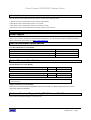
User Documentation Specifications
User Documentation Version Detail
Name of the User Document
Version Information
Dell PowerConnect 6024/6024F Systems Getting Started Guide
January 2005, P/N N5382, Rev. A01
Dell PowerConnect 6024/6024F Systems User's Guide
January 2005, Rev. A03
Dell PowerConnect 6024/6024F Systems CLI Reference Guide
January 2005, Rev. A03
System Firmware Specifications
System Firmware Version Details
Name of the Boot Code Image
Version No.
Release Date
6024x6024F-boot-v10013.rfb
1.0.0.13
February , 2004
Name of the Main Software Application Program Image
Version No.
Release Date
6024x6024F-sw-v2001.ros
2.0.0.1
April, 2005
Please see Dell PowerConnect 6024/6024F Systems User's Guide for instructions on updating the
system firmware.
Supported Firmware Functionality
Please see the Dell PowerConnect 6024/6024F Systems User's Guide, for details regarding the PowerConnect
6024/6024F system functionalities.
Hardware Versions Supported by This Release of the Firmware
PowerConnect 6024/6024F hardware version 00.01.64
Release Notes | Page 1
PowerConnect 6024/6024F Release Notes
NOTE: Dell PowerConnect 6024/6024F Ethernet Routing Switch is referred to as “the device” hereafter.
Added Functionality in This Release of the Firmware
Version 2.0.0.1 of the software application program is the second release of the system software for the device. It fixes
several defects found in the previous version of the firmware and adds some new functionality to the product. The
functions include: auto negotiation advertised capabilities, protected port (private VLAN edge port), SNMPv3,
enhanced port mirroring, Multiple Spanning Tree Protocol (MSTP), TACACS+, 802.1x port-based authentication,
Simple Network Time Protocol (SNTP), traceroute utility, telnet client, DNS client, and an easy set-up wizard. Please
see the Dell PowerConnect 6024/6024F Systems User's Guide for further details.
Important Notes on Firmware Installation (Upgrade and Downgrade)
Compatibility is critical for all firmware upgrades and downgrades. The start-up configuration file created by the older
version 1.0.2.7 of the software application is compatible with the new software application version 2.0.0.1. The reverse
is not true.
Please execute the following steps in order to upgrade the system to the software application version 2.0.0.1:
1) Transfer the new software application image via TFTP and set it as the system image that the device will load at
startup (for further details, consult the User's Guide).
2) [Follow this step only if you intend to use SSH] Re-generate RSA and DSA key pairs using the CLI commands
"crypto key generate rsa" and "crypto key generate dsa".
3) [Follow this step only if you intend to use HTTS] Re-generate HTTPS crypto certificate using the CLI command
"crypto certificate [number] generate".
Please note that the keys and certificates are not explicitly stored in the running and/or start-up configuration files. The
certificates and keys are stored in the hidden configuration file residing in the flash memory of the device. One can
view them using the CLI commands "crypto certificate request" and "show crypto key”.
One can downgrade the software application version 2.0.0.1 to the version 1.0.2.7, but the start-up configuration file
must be erased. Please execute the following steps in order to downgrade the software application version 2.0.0.1 to the
version 1.0.2.7:
1) Save the start-up configuration file by transferring it from the device to a management computer system via TFTP.
2) Edit the transferred configuration file as to remove configuration items applicable to the new system features
implemented in the software application version 2.0.0.1 (that is, the features not found in the older software application
version 1.0.2.7).
3) Erase the start-up configuration file in the device using "delete startup-config" CLI command.
4) Transfer the old version 1.0.2.7 of software application image via TFTP and set it as the system image that the device
will load at startup (for further details, consult the User's Guide).
5) Reboot the device.
6) Perform the initial configuration of the device.
7) Copy the edited configuration file from the management computer system back into the device via TFTP.
The above procedure is necessary because the configuration objects corresponding to the new system features added in
the software application version 2.0.0.1 will not be recognized by the older version 1.0.2.7. If such objects are
encountered by the older version 1.0.2.7 in the start-up configuration file, the latter will crash and reboot the device.
Please note that if you downgraded the device to the software application version 1.0.2.7 without following the above
steps you may experience continuous system crashing and rebooting. If that happens you must use Startup menu to
erase the start-up configuration file using "Erase Flash File" menu. In this case you start-up configuration file will be
permanently lost.
Release Notes | Page 2
PowerConnect 6024/6024F Release Notes
Issues Resolved in This Release of the Firmware
ID and Title
Description
Resolution
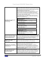
RN-16647-R-009. Selecting the
direction of the traffic to be
mirrored to the target
monitoring port.
There is no option to select the direction of the
monitored traffic on a port. Both incoming and
outgoing packets traveling through the monitored
port are copied to the target monitoring port.
This option exists in this
firmware release.
RN-17597-R-192. Copying and
pasting groups of CLI
commands into CLI session.
RN-17941-18902-19130-1913319134-R-210. Web Interface
inefficiency in handling large
tables with user controls.
RN-19034-P-239. The default
setting of the “Route Type” in
the "Router -> Global Routing
Parameters -> IP Static Route"
Web interface page.
RN-19775-19776-P-240. Usage
of the CLI commands “ip
http(s) port 0”
RN-12204-16699-R-080. The
behavior of the “show
{running|startup|backup}config" CLI commands.
RN-14516-R-089. Web
interface has no controls to
configure the STP BPDUs
filtering option.
The input/output mechanism of the device CLI
interface will not correctly process a large group of
commands pasted into the terminal window running
a CLI session via terminal emulator program, SSH
client program, or telnet client program. Please
avoid copying and pasting the groups of CLI
commands.
We recommend that you save the CLI commands
into a temporary file and then copy the file into the
running configuration of the device. For this
purpose please install the TFTP network server on
your management workstation and then use the
“copy tftp://[oob/]<ip-address>/<file-name> runningconfig” CLI command to transfer the file into the
device. Upon the successful download of the file,
the commands contained in the file are merged with
the running configuration file of the device.
It may take a Web browser a long time to process
the HTML/JavaScript Web pages that encode large
configuration tables with user controls (the
embedded Web server of the device generates the
HTML/JavaScript screens and then sends them to
the Web browser for rendering).
The setting of the “Route Type” in the "Router ->
Global Routing Parameters -> IP Static Route" Web
interface page should default to “Remote” instead of
“Reject”.
Do not use the CLI commands “ip http port 0” and
“ip https port 0”, as they will effectively disable the
operation of the HTTP or HTTPS Web server of the
device.
If the device was never configured before and is in
the same state as when you received it, then the
"show {running|startup|backup}-config" CLI
commands will not display the default system
configuration even though the device comes already
configured with some default parameters.
At present the above commands do not output the
default system configuration.
When Spanning Tree is disabled on a given
interface, all packets are flooded, by default.
Filtering STP BPDUs may be useful when a bridge
interconnects two regions and there is a need to
have a separate spanning tree for each region.
Filtering the BPDU in the bridge connecting the two
regions will serve this purpose. Therefore, you can
configure packets to be filtered, using the CLI. The
controls to perform this operation are absent in the
Web Interface. Please use the CLI interface to
configure STP BPDU filtering or flooding on an
interface.
This firmware release
supports copying and
pasting, groups of CLI
commands into a CLI
session.
Typically, large tables now
support a “Next Page”
mechanism.
The default setting for the
“Route Type” is now
“Remote”.
The ranges for ip http port
and ip https port are
changed, so that 0 cannot
be configured.
Default values of important
system parameters are
shown when displaying the
running configuration or the
startup configuration file.
STP BPDU is configurable.
Release Notes | Page 3
PowerConnect 6024/6024F Release Notes
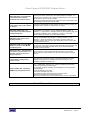
ID and Title
RN-15531-15292-R-076. The
pings with the packet size
larger than 1700 bytes are not
answered by the device.
RN-16640-10889-R-010. All
packets sent from the
monitoring port are always
tagged.
RN-16741-16649-R-138.
Viewing the port role
information of the Rapid
Spanning Tree Protocol.
RN-16857-R-071. The
limitations of SSL.
Description
At present, the router interface of the device will not
answer the pings with the packet size greater than
1700 bytes due to a limitation in the implementation
of the fragmented large frame reassembly
mechanism. When a ping is sent, a trap will be sent
to the sender.
The standard requires support for ping packets as
large as 65500 bytes. Please note, however, that
the fragmented frames, though allowed by the
standard, are not very common, and are considered
the frequent cause of network device problems.
At present the device tags every packet transmitted
from the mirroring target port even if the packet was
received untagged on the mirrored source port. This
includes packets in the default VLAN 1.
The device has no CLI or the Web interface
controls, which would allow viewing the port role
information (i.e. assignment and role transitions for
the DisabledPort, RootPort, DesignatedPort,
AlternatePort, or BackupPort port roles) of the Rapid
Spanning Tree Protocol (RSTP).
The information regarding port states (Blocking /
Listening / Learning/ Forwarding states) and
transitions between states can still be viewed via a)
CLI exec mode command “show spanning-tree” and
b) the Web interface “Switch -> Spanning Tree”
pages.
* The device supports SSL Version 3.0 and above
and does not support SSL Version 2.0
* The certificates are created by the system software
controlling the device and are not VeriSign
approved. The SSL certificates can be created
manually through an appropriate CLI command.
* The maximum number of SSL sessions is 12.
* The maximum number of Web HTTPS user
connections is 3.
Resolution
It is possible to receive
large ping packets.
It is possible to configure
whether mirrored packets
are transmitted: tagged or
untagged.
It is possible to view the
role information of RSTP.
SSL certificates can be
created manually, or
imported.
Other limitations are
described in the user
documentation.
RN-20095-P-218. The number
of supported IP Multicast
groups.
The device supports the maximum of 128 IGMP
groups at present.
The device now supports
up to 256 IGMP groups.
RN-20480-19459-P-227.
Configuring in-band and outof-band remote log servers.
The device allows configuring a remote log server
on both the in-band and out-of-band interfaces.
Adding both in-band and out-of-band remote log
servers via the Web interface will succeed (given, of
course, that the entered settings were valid).
However, attempting to configure both out-of-band
and in-band remote log servers via the CLI interface
will result in an error.
Out-of-band and in-band
remote log servers are
configurable both using the
CLI and the Web Based
Interface.
RN-20127-P-242. The default
OSPF stub metric.
By default, the device had assigned the OSPF stub
metric the value of 16777214.
This problem has been
fixed in the latest software
version, so that the default
is explicitly set to 1.
Release Notes | Page 4
PowerConnect 6024/6024F Release Notes
ID and Title
RN-18245-P-243. Reordering
of the ACEs in an ACL.
RN-17098-P-230. Modifying
the running configuration file
while it is being displayed.
RN-18759-18957-P-233. The
maximum number of IP
interfaces supported on the
out-of-band management port.
RN-00000-R-006. The autonegotiation and the
advertisement of maximum
port capabilities.
RN-18990-P-235. Correction of
the Port Mirroring Web
interface help screen.
RN-19003-P-236. Correction of
the Storm Control Web
interface help screen.
Description
An Access Control List (ACL) consists of rules,
called Access Control Elements (ACE). The device
Web interface controls allow reordering of the ACEs
in an ACL. However, only unused priority (index)
numbers can be used for this purpose as assigning
a priority number already used in one ACE to
another ACE overwrites the first ACE.
Please always use only unused priority indexes
when renumbering the ACEs. Please note that
ACEs cannot be reordered using the CLI interface.
The device does not allow you to perform the
operation that modifies the running configuration file
while it is being displayed (using the “show runningconfig command”). This protection is necessary in
order to prevent the inconsistencies in the running
configuration file. When you attempt to modify the
running configuration of the device, a notification is
sent to another user displaying the running
configuration file at the same time..
The device supports up to 100 IP interfaces on the
out-of-band (OOB) management port. However, it is
highly recommended not to define more then 5 IP
interfaces on the OOB management port.
The device supports auto-negotiation, which allows
ports to auto-negotiate port speed duplex-mode
(only at 10 Mbps and 100 Mbps since ports
operating at 1000 Mbps support full duplex mode
only) and flow control. When auto-negotiation is
enabled (default), a port "advertises" its maximum
capabilities. These capabilities are by default the
parameters that provide the highest performance
supported by the port. At present, the device does
not allow modifying the capabilities that a port
"advertises" on a per port basis, i.e. all device ports
advertise their maximum capabilities.
Please note that in order for auto-negotiation to
work, ports at both ends of the link must be set to
auto-negotiate.
The help page for the “Switch -> Ports -> Port
Mirroring” Web interface page is incorrect and
should read as follows:
Status - Indicates the port state.
The possible field values are:
* Not Ready - Indicates that the port is not
currently being monitored.
* Active - Indicates that the port is currently being
monitored.
The device implements the packet storm control
mechanism. However, the device does not support
setting the maximum rate of unknown frames.
Disregard the information in the help screen of the
“Switch -> Ports -> Storm Control” Web interface
page related to the unknown packets.
Resolution
It is possible to configure
priority using the WBI.
User can perform
operations while displaying
running configuration file.
This is noted in the User
documentation. New
limitation is that user can
define only 5 IP interfaces
on OOB port.
This fix to the user
documentation is no longer
relevant, because this
feature is now supported
(already added above to
new features description)
Text corrected in the help
page and the User Guide.
Text has been fixed in the
help page and in the User
Guide.
Release Notes | Page 5
PowerConnect 6024/6024F Release Notes
ID and Title
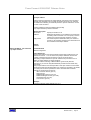
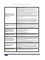
RN-11066-11896-F-056. The
QoS mode: marking of the
DSCP.
Description
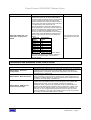
In the Quality of Service (QoS) mode, the user may
configure the system to use the IP Differentiated
Services Code Point (DSCP) of the incoming packet
to map the packet to the output priority queues.
Please note that when the device maps IP DSCP to
priority queue, the original VLAN Priority TAG (VPT)
is not kept and the VPT value is set to 0.
Because the DSCP to queue table determines the
queue assignment in the device, 8 DSCP codes are
reserved for enabling the mapping to the 8 available
queues. For this purpose 8 DSCP values are
reserved and will not be available for user mapping.
These DSCP values will always be mapped to the
following output queues (user cannot change the
values):
Reserved
Fixed output
DSCP
queue
DSCP 3
q1
DSCP 11
q2
DSCP 19
q3
DSCP 27
q4
DSCP 35
q5
DSCP 43
q6
DSCP 51
q7
DSCP 59
q8
Packets may be marked with the queue’s DSCP,
even if the mapping was not selected, instead of
preserving the original DSCP. This occurs on
reserved queues.
Resolution
Text has been fixed in the
help page and in the User
Guide.
Corrections and Additions to the User’s Guide
Web Screen / Section in Guide
RN-CA-UG-01. Advanced
Configuration
RN-CA-UG-02. DHCP IP Interface
RN-CA-UG-03. SNMP Access
Control Group Settings.
Description of Change
The in-band ports of the Vesuvio are router ports. Therefore, when an interface
is defined on the in-band ports (or VLAN of which they are members), no
default-gateway is configured. After dynamic assignment of the IP interface,
manually assign a default route.
The in-band ports of the routing switch are potentially routing ports. Therefore,
when an interface is defined on the in-band ports (or VLAN of which they are
members), no default-gateway is configured. After dynamic assignment of the
IP interface, manually assign a default route.
The index of the group name table consists of Group Name, Security Model,
and Security Level. Different views for the same group can be defined with
different security levels. Thus, for example, after having created the
appropriate views, a group can be created for which "no authentication" is
required, while allowing only notification view for "interfaces". A group of the
same name can be created for which "priv" authentication is required. For
example, you can configure Read views for this group for mib2, and write
views for interfaces. In this case, users in this group who send "priv" packets
can modify all "interfaces" MIBs and view all mib2.
Release Notes | Page 6
PowerConnect 6024/6024F Release Notes
RN-CA-UG-04. The functioning of
BootP
RN-CA-UG-05. The supported
OSPF features.
The device incorporates BootP and DHCP clients that solicit an IP address to
use as the system IP address on each interface. The BootP client is
operational on system startup only if no IP interface is defined and DHCP client
is not configured to work. This is the factory default setting. The BootP client
will continuously try to find a BootP server by sending BootP requests to all
VLANs and ports (including the out-of-band management port) until either of
the following events occurs:
1) A BootP server replies in which case the reply is used to provide the system
with an IP address on the interface, on which the reply is received (all other
interfaces have to be assigned IP addresses by other means).
2) The user starts to manually configure the system (command-line activity of
any kind is detected on the serial console port).
An IP address will be considered static by the device when either a) acquired
automatically via BootP or b) set manually via a management interface.
The device supports the following OSPF features:
* Virtual links
* ECMP
* OSPF default cost of an OSPF interface.
* Cryptographic authentication.
At present the device does not support all other OSPF features.
Corrections and Additions to the CLI Reference Guide
CLI Command
RN-CA-CLIRG-01. CLI command
“passwords min-length”
RN-CA-CLIRG-02. CLI command
“ip address dhcp”
RN-CA-CLIRG-03. CLI command
“ospf”
RN-CA-CLIRG-04. CLI command
“ip route”
Description of Change
User Guidelines: The length of passwords that were defined before the
minimum password length requirement was configured is not checked on
subsequent logins. This command is not enforced retroactively.
Every in-band port of the switch can potentially become a routing port.
Therefore, when an interface is defined on an in-band port (or a VLAN of which
it is the member), no default-gateway is configured. After dynamic assignment
of the IP interface, you may assign a default route manually.
The correct syntax is ospf [area-id]. (The ospf command area parameter is
optional.)
Note the following user guidelines (detailed further in this document):
* If the specified area-id has not yet been created, using the ip interface
configuration ospf area command, then it is auto-created using this command.
* Note that an OSPF area that is auto-created is not displayed in the
configuration file.
* Note that an auto-created OSPF area is deleted only after a subsequent
reboot, if the OSPF interface is deleted.
* If no area is designated, the backbone area is associated with the IP
interface. If the backbone has not yet been created, it is auto-created.
* Note that the negation of the area command does not appear in the
configuration file, because it is, in fact, the default. However, it does appear
when using the "show ospf” command, because it was automatically created.
If reject-route is designated, this will discard all packets matching this route per
RFC-2096, and handle them as reject-route. These routes are treated as
unreachable networks, and an "ICMP unreachable route" is returned.
Release Notes | Page 7
PowerConnect 6024/6024F Release Notes
Note: This CLI command replaces “rip default-route offset” command.
rip default-route originate
The rip default-route originate interface configuration command generates a
metric for a default route into RIP. To disable this feature, use the no form of
this command.
Syntax
rip default-route originate metric
no rip default-route originate
metric — Metric for a default route. (Range: 1- 15)
Default Configuration
By default, the feature is disabled.
RN-CA-CLIRG-05. CLI command
“rip default- route originate”
Command Mode
IP Interface Configuration mode
User Guidelines
* This command is equivalent to rip default-route offset.
* Note that this is an origination of a default route with the given metric.
* Setting the value of the metric to 0 is the same as negating the command.
* An interface on which this command has been configured does not accept
"default route" advertisement, in order to prevent a possible loop on the default
route.
RN-CA-CLIRG-06. CLI command
“rip default-route offset”
Example
The following example applies a metric of 5 to generate a default route to RIP
on IP address 100.1.1.1.
console(config)interface ip 100.1.1.1
Console(config-ip)# rip default-route originate 5
Note: This CLI command has been deprecated.
* This command is equivalent to rip default-route originate.
* Note that this is an origination of a default route with the given metric.
* Setting the value of the metric to 0 is the same as negating the command.
* An interface on which this command has been configured does not accept
"default route" advertisement, in order to prevent a possible loop on the default
route.
* The range of the parameter offset is 0 - 15, and not as noted in the CLI
Reference Guide.
The area-id is the OSPF area associated with a range of IP addresses. The
area-id is specified in a “dotted decimal” notation similar to an IP address.
If no area is specified, the default area is 0.0.0.0.
RN-CA-CLIRG-07. CLI command
“router ospf area”
An OSPF routed network must contain an area 0. Only one sub-level of area
hierarchy is allowed, that is all areas other than 0 must connect to area 0 via
an ABR (area border router). An ABR is a router that is connected to two or
more OSPF areas.
Small networks usually will only have an area 0. Larger networks will have
multiple OSPF areas to reduce the size of the IP route tables and to reduce the
CPU and memory demands on the routers to a manageable level.
It is not necessary to define an OSPF area globally. OSPF areas may also be
defined with the interface command.
Release Notes | Page 8
PowerConnect 6024/6024F Release Notes
RN-CA-CLIRG-08. CLI command
“router ospf redistribute rip”
RN-CA-CLIRG-09. CLI command
“show ip ospf neighbor”
The router ospf redistribute rip global configuration command enables
incorporating IP routes that have been learned via the RIP routing process
into the OSPF routing process. To disable the redistribution of RIP routes,
use the no form of this command.
By default, the redistribution of RIP routes is disabled.
If your network contains other routers that do not run OSPF, but do run
RIP routing protocols, the OSPF process can incorporate those routes
learned via RIP. When redistribution is enabled, the router becomes an
“AS Boundary Router” (ASBR).
OSPF is more robust and converges more rapidly than RIP. Redistribution of RIP routes should be used with care to avoid network
instability. Redistribution should be done only in one direction. If RIP routes
are redistributed into OSPF, do not redistribute the same OSPF networks
back into RIP.
For OSPF routers to become neighbors, they must be directly connected
and agree on:
* IP prefix and subnet mask
* Area ID
* Authentication (none, text, MD5)
* Options (stub, nssa)
* Hello Interval (default 10 sec.)
* Router Dead Interval (default 40 sec.)
The OSPF neighbor state is one of (init, two-way, loading, full). On a
broadcast media, the roles are Designated Router (DR), Backup Designated
Router (BDR), Other (DRother)
RN-CA-CLIRG-10. CLI command
“vrrp preempt”
The router that owns the IP address or addresses associated with the virtual
router always preempts independent of the setting of this command.
RN-CA-CLIRG-11. CLI command
“snmp-server group”
In order to remove SNMP group please use the “no snmp-server group CLI“
command. The index of the group name table is comprised of Group Name,
Security Model, and Security Level. Different views for the same group can be
defined with different security levels. Thus, for example, after having created
the appropriate views, a group can be created for which "no authentication" is
required, while allowing only notification view for "interfaces". A group of the
same name can be created for which "priv" authentication is required. Readonly views can, for example, be configured for this group for mib2, and
read/write views for interfaces. In this case, the users belonging to this group
(the one who send "priv" packets) can modify all "interfaces" MIBs and view all
mib2.
RN-CA-CLIRG-12. CLI command
“snmp-server host”
The range for username in this command is 0 – 255.
RN-CA-CLIRG-13. CLI command
“snmp-server v3-host”
The range for retries in this command is 0 – 255.
The range for username in this command is 1 – 24 characters.
Note that the type of trap (that is notification or inform) depends on how the
trap receiver has been configured.
RN-CA-CLIRG-14. CLI command
“spanning-tree mst-prioriry”
The range for instance-id is 1 – 15.
RN-CA-CLIRG-15. CLI command
“instance (mst)”
The range for VLAN is 1 – 4093.
RN-CA-CLIRG-16. CLI command
“logging”
The target IP address can be specified either in the standard decimal dotted
notation format or as a fully qualified domain name.
Release Notes | Page 9
PowerConnect 6024/6024F Release Notes
RN-CA-CLIRG-17. Reporting of
shorts in Virtual Cable Testing
(VCT).
RN-CA-CLIRG-18. The
responsiveness of the device
during the configuration file
copying.
RN-CA-CLIRG-19. The
precedence of port bound and
VLAN bound ACLs.
The device reports only shorts across the cable pairs. The Virtual Cable Test
(VCT) analyzes each of the MDI pairs in the cable being tested. Typically, in a
CAT5 RJ-45 cable, the positive and negative of each pair are twisted together.
The pairs that are twisted together are identifiable: solid orange and striped
orange, solid blue and striped blue, solid green and striped green, solid brown
and striped brown are twisted together. If, for example, MDI[0]+/- pins are
connected to pairs 1,2 of the RJ45, which are connected to the orange pair,
then MDI[0]+ will be connected to the solid orange and MDI[0]- will be
connected to the striped orange. The short between wires that do not belong to
the same pair will not be reported.
While a configuration file is being copied intra-device and via TFTP (i.e.
downloaded or uploaded), the device ignores the user input sent to the device
via CLI or Web interface. Note that this behavior only applies to the session in
the context of which the copying is taking place; all other management
sessions may experience a delayed responsiveness but will accept CLI
commands and process HTTP requests.
If an ACL X is bound to a port and the port becomes a member of the VLAN to
which a different ACL Y is bound, then the ACL Y bound to the VLAN overrides
the ACL X bound to the port.
The default rule cannot be changed manually.
Release Notes | Page 10
PowerConnect 6024/6024F Release Notes
The “ip helper-address” command is missing from the CLI Reference Guide.
ip helper-address
Use the Global Configuration ip helper-address command to have the device
forward User Datagram Protocol (UDP) broadcasts received on an interface.
To disable the forwarding of broadcast packets to specific addresses, use the
no form of this command.
ip helper-address ip-interface address [udp-port-list]
no ip helper-address ip-interface address
Syntax Description
ip-interface
address
udp-port-list
Specify IP interface or all.
Destination broadcast or host address to be used when
forwarding UDP broadcasts. You can specify 0.0.0.0 to
indicate not to forward the UDP packet to any host.
The broadcast packet destination UDP port number to
forward. If not specified, packets for the default services
are forwarded to the helper address.
Default
Disabled
RN-CA-CLIRG-20. CLI command
“ip helper-address”
Command Mode
Global Configuration
Usage Guidelines
The ip helper-address command forwards specific UDP broadcast from one
interface to another. You can define many helper addresses but the total
number of address-port pairs is limited to 128 for the whole device.
The setting of helper address for specific interface has precedence over a
setting of helper address for all the interfaces.
You can't enable forwarding of BOOTP/DHCP (ports 67,68) with this
command. If you want to relay BOOTP/DHCP packets use the DHCP relay
commands.
The ip helper-address command specifies a UDP port number for which UDP
broadcast packets with that destination port number are forwarded. By default,
if no UDP port number is specified, the device forwards UDP broadcast
packets for the following six services:
IEN-116 Name Service (port 42)
DNS (port 53)
NetBIOS Name Server (port 137)
NetBIOS Datagram Server (port 138)
TACACS Server (port 49)
Time Service (port 37)
Example
Console(config)# ip helper address 100.10.1.1
Release Notes | Page 11
PowerConnect 6024/6024F Release Notes
System Usage Notes
ID and Title
Description
RN-00000-F-086. The supported
Web browsers and platforms.
The web management interface of the device supports Microsoft Internet
Explorer Version 6.0.
RN-00000-F-204. Idiosyncrasy of
the VPT to Queue mapping table.
RN-00000-R-053. Deleting VLAN
interface with the attached Access
Control List (ACL).
RN-15139-R-077. Potential affect
of the QoS settings on the
configuration file download via
TFTP.
RN-15535-F-011. The functioning
of the mirroring port when the
volume of the mirrored traffic flow
is greater than bandwidth capacity
of the mirroring target port.
RN-15585-R-146. Interpreting the
diagnostics results of Virtual
Cable Test (VCT): 2-pair vs. 4-pair
cables.
The device allows simultaneous mapping of multiple VLAN Priority Tags
(VPT) values to a single output queue (via the CLI command “wrr-queue
cos-map”, for example). However, We recommend that you always map
one VPT to one queue, rather than mapping multiple VPTs to a single
queue.
The device allows deletion of a VLAN interface even if it has an Access
Control List (ACL) bound to it. Deletion of the VLAN interface results in
automatic unbinding of the attached ACL. If/when, the VLAN interface is
re-created in the device; the ACL will be automatically re-bound to the
VLAN interface.
Here is an illustration of the above description:
1) Create VLAN 2.
2) Create a dummy ACL X
3) Bind the ACL X to VLAN 2.
4) View the ACL binding table – the association between VLAN 2 and the
ACL X will be present.
5) Delete VLAN 2.
6) View the ACL binding table – the association between VLAN 2 and the
ACL X will be gone even though the information about the association
between ACL X and VLAN 2 is retained by the system.
7) Re-create VLAN 2.
8) View the ACL binding table – the association between VLAN 2 and the
ACL X will be present again.
In essence, deleting an interface automatically unbinds the ACL attached
to the interface; if the same interface is recreated, the deleted ACL is
rebound to the interface.
If the device has plenty of Quality of Service (QoS) flow classification and
bandwidth management objects like ACLs and policies defined and bound
to interfaces then the download (copy) of a configuration file from the
TFTP server into the running or startup configuration of the device may
take a very long time or even fail.
It is recommended then to perform the TFTP transfer of the file into the
backup configuration file first, and then copy the backup configuration file
into the running or startup configuration file.
When both transmit (TX) and receive (RX) directions of more than one
port are monitored, the volume of the actual traffic that that flows through
the monitored ports may exceed the carrying capacity of the target
monitoring port. In this case, the division of the mirrored packets may not
be equal and the mirroring target port may transmit an arbitrarily selected
subset of the traffic while some of the mirrored frames may be dropped.
The user is advised to use caution in assigning port monitoring.
The Virtual Cable Test diagnoses the quality and characteristics of a
copper cable attached to a port. The test can be performed via the CLI
command “test copper-port tdr” or the Web interface page “System ->
Diagnostics -> Copper Cable Testing.” Please note that the displayed
diagnostics results will differ for four-pair and two-pair cables. If the
diagnostics test is performed on a four-pair cable (given that the cable is
intact), the resulting message will read as "Cable on port <port-number> is
good." If the diagnostics test passes for a two-pair cable, the resulting
message will read as "Cable on port <port-number> has only two pairs".
The latter message does not indicate that there is a problem with the
cable. It should be construed as follows: the test passed and there are
only two pairs in the tested cable.
Release Notes | Page 12
PowerConnect 6024/6024F Release Notes
RN-16193-16178-F-001. The
Jumbo frames feature is defined
only for the ports operating at the
gigabit speed.
RN-16203-F-037. The DHCP “selfreference” in a downloaded
configuration file may cause the
perpetual configuration-reboot
cycle.
RN-16350-S-125. The ambiguity of
the Current Port Status reading in
the Web interface page "Switch ->
Network Security -> Port
Security".
RN-16514-R-078. The mutual
exclusion mechanism is absent
for the concurrently initiated
system reset and copying of the
configuration file.
The device supports jumbo frames on all Gigabit Ethernet ports. Jumbo
frames accepted at ingress port generate jumbo frames at egress port.
Please note, although Jumbo frames are routinely transmitted from the
ports operating at 10/100 Mbps, the incoming Jumbo frames are always
dropped by the ports operating at 10/100 Mbps.
When the Jumbo frames feature is enabled, the device still bridges and/or
routes frames of normal size to and from the interfaces attached to the
device ports operating at 10/100 Mbps.
It is possible to cause an endless “load configuration” / “system reload”
cycle by downloading the configuration file, which contains instructions
enabling the DHCP on the interface that connects to the DHCP server
where the configuration file is being downloaded from.
While this is clearly not a desirable situation, it really has nothing to do
with the device itself and may only result from the incorrect use of the
device by the user. It is naturally the user's responsibility to make certain
that the configuration files contain the appropriate information.
If a port becomes a member of Link Aggregation Group (LAG in short, also
known as port-channel) then the configuration setting of MAC address port
locking mechanism of this port will temporarily assume the value of the
corresponding LAG setting until the port is removed from the LAG.
The value of the “Current Port Status” status field contained in the “Switch
-> Network Security -> Port Security“ Web interface page will always
reflect the effective status of port the LAG and may falsely appear to be in
the conflict with the "Set Port" setting which is only in effect when the port
does not belong to a LAG. At the same time, the output of the CLI exec
mode command “show ports security” will display the status of the port as
being the member of the LAG without referencing the actual port status.
For example, a locked port g17 is made a member of unlocked LAG 1. As
long as it remains a member of the unlocked LAG 1, g17 is effectively
unlocked and the relevant “Switch -> Network Security -> Port Security“
Web interface page will display the port status as “Unlocked”. When the
port g17 leaves the LAG 1, it will become locked and the “Switch ->
Network Security -> Port Security“ Web interface page will display the port
status as “Locked”.
The device does not protect a user against performing a system reset
(reload) while another user is copying a configuration file. Caution should
be exercised when resetting the device as no to disrupt the ongoing
copying/downloading of the configuration file.
The user attempting to reset the device while another user is copying the
configuration file will receive a warning message but will not be prevented
from going ahead with the reset.
Release Notes | Page 13
PowerConnect 6024/6024F Release Notes
RN-16620-19743-19744-1685419556-R-128. Several device
controls are not available via the
Web interface.
RN-16621-R-072. The functioning
of the SSH.
RN-16767-32011-F-040.
Miscellaneous constraints of
OSPF functionality and nuances
of the OSPF configuration
settings.
RN-16823-P-244. Common STP
cost 4 for LAGs and Gigabit
interfaces.
RN-19658-P-229. The Web
interface may not reflect the
differences between the fiber and
copper port configurations.
RN-17103-N-108. There are no
statistics available for the
discarded packets.
RN-17140-P-231. Deleting the
mapping of a protocol from a
protocol group.
There are no controls in the Web interface of the device corresponding to
the following CLI commands:
1) the line configuration command which sets the interval that the system
waits until user input is detected ("line console", "exec-timeout"),
2) the speed line configuration command which sets the line baud rate
("line console", "speed"),
3) the SSH related commands ("ip ssh port", "ip ssh server", "crypto key
generate dsa", "crypto key generate rsa", "ip ssh pubkey-auth", "crypto key
pubkey-chain ssh", "user-key", "key-string", "show ip ssh", "show crypto
key mypubkey", "show crypto key pubkey-chain ssh"),
4) the embedded Web server related commands (“ip http authentication",
“ip http port", "ip http server", “ip https authentication”, "ip https port", "ip
https server", "crypto certificate generate", "show ip http", "show ip https").
Please use the appropriate CLI commands for configuring the relevant
attributes of the device.
In addition, only the CLI interface can be used to define the order of
certain authentication methods. Here is an example of an authentication
method order that can be set via the CLI interface but cannot be entered
via the Web interface: “None, Remote, Local”. Please note, however, that
this order is quite irrelevant since “None” is always available as an
authentication method and, therefore, is equivalent to the authentication
method order “None”.
The device does not automatically generate and store the SSH keys. In
particular, the SSH keys are not automatically generated when the SSH
server is enabled.
The SSH keys are generated via the CLI commands “crypto key generate
rsa”, or “crypto key generate dsa”. These commands can be entered only
after SSH is enabled using the CLI command “ip ssh server”.
The device performs a graceful shutdown when OSPF is disabled. The
OSPF graceful shutdown lasts ten seconds, during which the user will not
be able to enter any CLI commands.
The OSPF tables have the following capacities:
* 128 OSPF interface table entries
* 64 OSPF area table entries
* 115 OSPF interfaces are supported per area.
* 64 OSPF neighbors table entries.
The Link Aggregation Group (LAG) interfaces of the device use the
Spanning Tree Protocol (STP) cost value of 4, which is the same STP cost
as for the Gigabit interfaces.
The Web interface of the device may sometimes not reflect the differences
between the fiber and copper ports in the Web pages containing the port
configuration settings. As a result, certain settings (as viewed via the Web
interface) may appear to exist for a particular port type while, in fact, they
are not available for that port type.
For example, the port duplex and speed settings while always appearing
as “Full 1000” are not indeed configurable on fiber ports, although they
appear to be configurable in the appropriate Web page.
The port counters can be viewed via a) CLI exec mode command “show
interfaces counters” and b) Web interface page “Statistics -> Table Views > Interface Statistics.”
However, the discarded packets are not shown. There is no option to
display the counters of the discarded packets. The same applies to the
RMON statistics, which can be viewed via a) CLI exec mode command
“show rmon statistics” and b) Web interface page “Statistics -> RMON ->
RMON Statistics.”
Before deleting the mapping of a protocol from a protocol group, the user
must first remove the ports bound to that protocol group.
Release Notes | Page 14
PowerConnect 6024/6024F Release Notes
RN-18463-P-232. Shutting down
the locked port after receiving
10,000 unauthorized packets.
RN-19630-F-226. MAC Access
Control List (MAC ACL)
referencing a nonexistent VLAN.
RN-32464-P-X01. The same IP
address can be configured to a
device interface and to a host
connected to the device.
RN-32590-P-X02. The output of
show ip route displays only
directly relevant information.
The device disables the ingress of the locked port whose “Action on
Violation” attribute is set to "Shutdown” and sends a trap only after the
locked port receives at least 10,000 unauthorized packets from an
unlearned sources.
It is possible to create a MAC Access Control List (MAC ACL) which
references a nonexistent VLAN. This feature allows defining the security
rules, which can match any VLAN ID regardless of whether or not the
VLAN was defined or dynamically created on the device.
For example, assuming that VLAN 5 does not yet exist in the device, the
following CLI configuration commands will still be accepted by the device
and successfully executed:
console# configure
console(config)# mac access-list test-mac-acl
console(config-mac-acl)# permit any any vlan 5.
The same IP address can be configured on the device interface and on a
device connected to the device. When a user configures an IP interface on
the device, there is no check to verify if a host connected to the device has
the same IP address.
The user must exercise caution in assigning IP addresses, to ensure that
the IP addresses on the device are unique to the network
The CLI command "show ip route" does not display the current values of
administrative distance and cost metrics for static and connected types of
routes. According to the feature definition, the router does not learn a
configured network, and the metric parameter is, therefore, superfluous.
To view metrics, display dynamic entries and static routes.
The CLI has two different IP interface commands for associating an IP
interface to an OSPF area:
Option 1:
Manually create the OSPF area, and associate it with an IP interface.
Use the global configuration router ospf area command to create an area.
Then use the ip interface configuration command ospf to associate the IP
interface with an area.
RN-32610-32294-P-X03. Multiple
IP interface commands perform
the same OSPF area function.
RN-32428-P-X04. It is not possible
to send traps on multiple ports per
IP address
RN-32103-P-X05. Auto Refresh
for Port and LAG Configuration
pages
RN-00000-F-X06. SNMPv3 Trap
Notification Setting.
Option 2:
Associate a non-defined OSPF area with an IP interface, causing it to be
automatically created.
An area can be auto-created. Use the IP interface configuration command
“ospf”, but designate an area that has not been created. This area is
automatically created.
Note that an automatically created area is not saved in the configuration
file, and exists only as long as the IP Interface with which it is associated
is not deleted. If the IP interface is deleted, and the device is subsequently
rebooted, the OSPF area disappears.
Note that the negation of the area command does not appear in the
configuration file, because it is, in fact, the default. However, it does
appear when using the “show ospf“command, because it was
automatically created.
A single IP port for sending traps can be defined on an IP address. In
order to send traps on multiple ports per IP address, a virtual IP address
can be defined, so that both stations reside on different IPs. Alternatively,
it is possible to use different NICs with different IP addresses.
When opening the Port and LAG configuration pages in the WBI, the user
may experience a double blink, caused by double refresh of the page. The
double refresh enables the device to retrieve actual status of the ports and
LAGs.
In order to enable an SNMP client to receive SNMPv3 informs from the
device, the SNMP client must be properly configured with the engine-ID
which is used in the corresponding SNMPv3 commands.
Release Notes | Page 15
PowerConnect 6024/6024F Release Notes
Known System Restrictions and Limitations
ID and Title
RN-00000-F-045. The ICMP
Redirect messages are not sent.
RN-00000-F-217. The limited
number of supported routes.
RN-00000-R-047. Distance Vector
Multicast Routing Protocol
(DVMRP) Tunnels are not
supported.
RN-10077-10078-09430-09421-F067. Several Ethernet counters
are not supported.
RN-00000-F-017. IGMP reports in
the [224..239].[0|128].0.[0..255] IP
Multicast ranges.
Description
ICMP Redirect messages are used by routers to notify the hosts on the
data link that a better route is available for a particular destination. At
present, the device does not send ICMP Redirects.
The device supports the total of 12,000 routes which are internally
allocated as follows:
* 4,000 prefixes (the maximum number of network routes).
* 8,000 host (/32) routes (this is also the maximum number of next hop
routers which can be configured on the device).
DVMRP Tunnels allow the exchange of IP multicast traffic between routers
separated by networks that do not support multicast routing. At present,
the device does not support DVMRP Tunnels.
The device does not support the following Ethernet counters:
* Alignment Errors
* Symbol Errors
* Ethernet like MIB dot3StatsLateCollisions
The device does not accurately accumulate the following Ethernet
counters:
* dot3StatsSingleCollisionFrames
* dot3StatsMultipleCollisionFrames
Avoid using the IP Multicast address groups within the following ranges:
224.0.0.[0-255]
225.0.0.[0-255]
226.0.0.[0-255]
227.0.0.[0-255]
228.0.0.[0-255]
229.0.0.[0-255]
230.0.0.[0-255]
231.0.0.[0-255]
232.0.0.[0-255]
233.0.0.[0-255]
234.0.0.[0-255]
235.0.0.[0-255]
236.0.0.[0-255]
227.0.0.[0-255]
238.0.0.[0-255]
239.0.0.[0-255]
224.128.0.[0-255]
225.128.0.[0-255]
226.128.0.[0-255]
227.128.0.[0-255]
228.128.0.[0-255]
229.128.0.[0-255]
230.128.0.[0-255]
231.128.0.[0-255]
232.128.0.[0-255]
233.128.0.[0-255]
234.128.0.[0-255]
235.128.0.[0-255]
236.128.0.[0-255]
237.128.0.[0-255]
238.128.0.[0-255]
239.128.0.[0-255]
The device assumes the packets within the above ranges of IP Multicast
addresses to be part of the network control traffic. These packets will not
be snooped.
RN-10470-F-101. The margin of
error of Virtual Cable Testing
(VCT).
The copper cable length reported by the Virtual Cable Test may vary by
several meters.
RN-11125-10972-F-022. The effect
of head-of-line blocking
prevention mode on the storm
control.
When the device operates in the head-of-line blocking prevention mode
(the flow control mechanism is disabled) the functioning of the Storm
Control feature which limits the traffic rates at the port ingress may deviate
from the expected behavior. This phenomenon is more perceptible when
a port with enabled rate limiting operates at a lower speed (10 Mbps, for
example).
Release Notes | Page 16
PowerConnect 6024/6024F Release Notes
RN-12534-15454-P-048. Adding an
invalid VRRP interface via Web
interface.
RN-14180-11588-F-062. Precision
of QoS settings of policing and
shaping.
RN-14701-14702-32775-3277618891-R-041. Miscellaneous
constraints of RIP functionality
and nuances of RIP configuration
settings.
RN-15042-F-025. The limitation of
the maximum number of VLANs
and ports.
RN-15733-R-084. There is no
checking performed when a
configuration file is copied via
TFTP (downloaded) into the
backup configuration file of the
device.
When adding a new VRRP interface with an invalid IP address via the
Web interface the device will display an appropriate error message but still
add a virtual router entry to the VRRP Table. Please always manually
delete the invalid virtual router entry.
Please note that if the admin status of the virtual router is set to “Up”, the
router cannot be deleted. In addition, the field itself cannot be modified.
The actual value of the user configured QoS settings of the traffic policing
and shaping may deviate from the values assigned by the user. For
example, the user may specify a committed rate (average traffic rate in
bps) of 20000000, but the actual rate will be 19531000.
This behavior may also affect the rate limiting mechanism (ingress shaping
and egress policing) when it is performed at very low rates.
In typical enterprise applications (for the rates of 1Mbps and above) the
impact of this errata should be insignificant.
* The device does not support RIP2PeerTable, which is (using RFC
terminology) is an optional cache of recently heard neighboring routers.
* Poison-reverse is automatically enabled after route update; and activated
after two minutes, thus relieving the user from configuring the exact
behavior.
* The system sends only default routes on all interfaces, until a RIP
response is received.
* The user can specify the version of RIP (RIPv1 or RIPv2) to be
supported on the interface. The device is set to RIPv1 by default, and not
RIPv2.
* By default, RIP is disabled per interface and per system. RIP-1
compatibility mode is not supported.
* By default, RIP redistributes static routes.
* The device currently supports the “Receive Only” (RX) and “Receive and
Transmit” (RX & TX) modes for RIP and does not support the “Transmit
Only” mode.
* Default routes are automatically created.
The device imposes a limitation on the maximum number of port-perVLAN combinations. The following formula describes the limitation:
L = N * (P1 + P2+…+ Pn) < 65536
Where
L – denotes the system property which is subject to limitation
Pi – denotes number of ports belonging to the VLAN i
N – denotes total number of VLANs with at least one port
If L is less then 65536 then the limit is not reached.
For example, if three VLANs exist in the device and 10 ports belong to
VLAN 1 (the default VLAN), 14 ports are to be made the members of
VLAN 2, and 16 ports are to be made the members of VLAN 3, then
L = (10 + 14 + 16) * 3 = 120.
Since L is less then 65536 it follows that the system limit has not been
reached and the configuration is valid.
When a configuration file is copied intra-device or via TFTP (downloaded)
into the running or startup configuration file of the device, the commands
in the file are syntactically and semantically checked and the user is
always notified if the file has an error (the copy operation will fail and the
running or startup configuration file will not be altered).
However, the user must use caution when copying (downloading) a
configuration file from a TFTP network server to the backup configuration
file of the device because the check of the file being downloaded is not
performed. In fact, a file of an arbitrary nature may be transferred and
stored in the backup configuration file. An attempt to display the contents
of an invalid backup configuration file via “show backup-config” CLI
command may result in unpredictable system behavior.
Release Notes | Page 17
PowerConnect 6024/6024F Release Notes
The device supports up to 4095 VLANs. However, one can actually create
only 4062 VLANs (2 through 4063) because: a) VLANs 4064 through 4094
are reserved by the device for the internal operational usage, b) VLAN 1 is
the default VLAN of which all ports are members by default, and c) VLAN
4095 is designated as the "Discard VLAN."
At present the device has a limitation of the following kind:
If more then 2000 static VLANs are to be created in the system then the
user must always use the range command qualifier to minimize the
number of “vlan” CLI commands in the configuration file as to avoid the
overflow of the internal configuration file buffer. Alternatively, create half in
one command, and the other half in another.
Let us illustrate the point. Let us suppose that the total of 2010 static
VLANs must be created. Then instead of creating them using the method
A always use the methods B or C:
RN-15950-F-184. Creating more
the 2000 static VLANs
simultaneously.
Method A (inconsecutive VLAN numbers)
Never use this method
console# configure
console(config)# vlan database
console(config-vlan)# vlan 2, 4, 6, 8, …4018, 4020
console(config-vlan)# exit
Method B (consecutive numbers of VLANs)
You may use this method
console# configure
console(config)# vlan database
console(config-vlan)# vlan 2-2011
console(config-vlan)# exit
Method C (two or more commands to define many VLANs)
You may also use this method
console# configure
console(config)# vlan database
console(config-vlan)# vlan 2, 4, 6, 8, …2008, 2010
console(config-vlan)# vlan 2012, 2014 …4018, 4020
console(config-vlan)# exit
RN-16114-16118-F-104. Optical
transceiver diagnostics and the
supported SFP transceivers.
RN-16524-P-228. Configuring the
SNMP alarm table OID
1.3.6.1.2.1.4.3.
RN-16622-R-139. The number of
authentication retries for the SSH
and telnet server.
RN-16955-32807-R-044. When
using RIP all networks are
advertised by default.
.
The device performs the optical transceiver diagnostics only on the Small
Form Factor Pluggable Gigabit Interface Converters (SFP GBICs, also
known as SFP transceivers) which support the Digital Diagnostic Standard
SFF-4872 or are compatible with the Finisar SFP transceivers.
Please note that the TX fault diagnostic testing is not supported by the
Finisar SFP transceivers.
The device does not allow configuring the SNMP alarms for the variables
of the alarm table located at the OID 1.3.6.1.2.1.4.3 tree-top.
The device does not support controls for configuring the number of
authentication retries for the embedded SSH and telnet servers. The
authentication retries default is permanently set to 3.
Please note that device supports the configuration of a number of
authentication retries for the outgoing authentication-request passwords
sent to RADIUS server by the embedded RADIUS client. Please see
“radius-server retransmit” CLI configuration mode command and “System > Management Security -> RADIUS” or “System -> Out-of-band ->
RADIUS” Web interface pages.
The device has no user controls to prevent the advertisements of certain
networks when using RIP. The command “no router rip redistribute
connected" is not implemented. Therefore, the directly connected routes
are advertised by default. By default in RIP all networks are advertised.
Please note that this limitation does not apply to OSPF since the “no
router ospf redistribute connected” command was implemented.
Release Notes | Page 18
PowerConnect 6024/6024F Release Notes
RN-17206-N-019. The granularity
of broadcast and multicast
maximum rate of storm control.
The maximum rate of broadcast and (optionally) multicast frames allowed
on each port will be rounded off to the nearest multiple of 64 Kbps. For
example, if the maximum rate is set to 129 Kbps then the device will round
off the rate and set the rate to 192 Kbps.
Please note that the device does not support the storm control (that is, the
rate limiting) for the unknown unicast traffic.
RN-17605-R-161. Removing the
static routes when an IP interface
is deleted.
The device automatically removes a static route to a next hop router if the
corresponding IP interface is deleted from the system.
RN-18904-18908-P-234. The
inaccuracies in the Web interface
statistics diagrams.
RN-19803-P-241. ACL to port
binding limitation.
RN-32810-P-X06. The same MAC
Address is used for STP BPDUs
on different ports
RN-32158-P-X07. After rebooting
the device, synchronization can
be done only using Unicast or
Anycast servers.
RN-TT118808-P-X08. System
relays DHCP messages when
server is local.
RN-TT76305-P-X09. Removing
SNMP trap host generates error.
The diagrams with certain statistical information may deviate from the
actual values. For example, “% Error Packets Received” column in
“Statistics -> Table Views -> Utilization Summary” Web interface page and
the “Interface Statistics” of the "Statistics -> Charts -> Ports” Web
interface page may display inaccurate statistical data.
The device allows binding only one ACL to a port at a time. It may appear
from the Web interface page “System -> Network Security -> ACL
Bindings -> Show All” that there is an option to bind more than one
interface; however, this is not the case. Attempting to bind a second ACL
to a port results in an error.
The source MAC address contained in Configurations BPDUs transmitted
by each Port on the device does not uniquely identify the transmitting Port,
as required per standard. Note that this in no way adversely affects
network or device behavior.
Synchronization of time using broadcast servers may not work after
reboot. Note that synchronization can be done with Unicast or Anycast
servers.
The DHCP relay feature will relay DHCP messages on the DHCP server's
local interface. The device relaying local DHCP messages will cause
duplicate messages to be received by both client and server. The
duplicate messages will be ignored.
Removing an SNMP trap host via the CLI interface generates the following
error: "TMibScalarC_SetValue: var: rndCommunityString mismatching
between var mib type and object type!"
For example, the above message will be displayed if one executes the
following steps:
1) Add IP address to the VLAN.
2) Connect an SNMP trap client.
3) Configure the device to send traps to connected client.
4) Remove the SNMP trap host through the CLI.
Please note that the entry is removed even though an error is generated.
End of Release Notes
Release Notes | Page 19