1
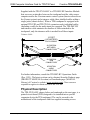
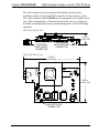
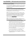
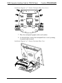
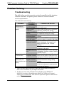
This document was prepared and written by the Technical Documentation department at:
Crestron Electronics, Inc.
15 Volvo Drive
Rockleigh, NJ 07647
1-888-CRESTRON
Crestron TPS-XVGA-BV
RGB Computer Interface Card for TPS/Tilt Panel
Contents
RGB Computer Interface Card with Balanced Video for
TPS/Tilt Panel: TPS-XVGA-BV
1
Description
Functional Description
Physical Description
Leading Specifications
Computer Video Connector Signals
Preparation
Installation and Hookup
Touchpanel Setup
Configuring the Touchpanel
SIMPL™ Windows® Programming
VT Pro-e Setup
Problem Solving
Troubleshooting
Further Inquiries
Future Updates
Future Firmware Upgrades
Appendix: Optional Touchpanel Setups
Serial Mouse Control Driver
Telestrator Video Annotation Device
Return and Warranty Policies
Merchandise Returns / Repair Service
CRESTRON Limited Warranty
Operations & Installation Guide - DOC. 5920
1
1
2
4
5
5
7
13
13
13
13
14
14
15
15
15
16
16
17
18
18
18
RGB Computer Interface Card with Balanced Video for TPS/Tilt Panel: TPS-XVGA-BV • i
Crestron TPS-XVGA-BV
RGB Computer Interface Card for TPS/Tilt Panel
RGB Computer Interface Card with
Balanced Video for TPS/Tilt Panel:
TPS-XVGA-BV
Description
Functional Description
The TPS-XVGA-BV RGB computer interface card with balanced video
is an optional feature designed for Crestron’s Isys™ TPS-5000 and
TPS-6000 tilt touchpanels. Through an RGB window on a page within
the uploaded VisionTools™ Pro-e (VT Pro-e) touchpanel project, the card
allows computer video to be displayed on the touchpanel full screen or in
a window. Non-interlaced input video resolutions of up to 1600x1200 are
supported. The resolutions are supported by scaling or sub-sampling in
the H-direction and scaled down in the V-direction to the native
resolution (or lower) of the touchpanel. Lower resolutions may be scaled
up to fill the touchpanel screen.
NOTE: The TPS-XVGA-BV can only be installed into specific
TPS-5000 and TPS-6000 tilt touchpanels. On the underside of the
touchpanel base in the lower-left section of the barcode label, check the
Crestron ZA number. Refer to the following table for the touchpanels that
are capable of using the TPS-XVGA-BV.
TPS-XVGA-BV Capable Touchpanels
TOUCHPANEL ZA NUMBER
TPS-5000
TPS-6000
ZA11500
ZA11501
Optional touchpanel setups are also available to utilize the TPS-XVGABV. Serial mouse control driver software and instructions to integrate a
Boeckeler Pointmaker® Video Marker telestrator with the TPS
touchpanel are provided. For further information, refer to “Appendix:
Optional Touchpanel Setups” that begins on page 16.
Operations & Installation Guide - DOC. 5920
RGB Computer Interface Card with Balanced Video for TPS/Tilt Panel: TPS-XVGA-BV • 1
RGB Computer Interface Card for TPS/Tilt Panel
Crestron TPS-XVGA-BV
Supplied with the TPS-XVGA-BV is a TPS-IMC-BV Interface Module
that serves as an interface between the touchpanel and the video source
computer and/or the Crestron remote control system (herein referred to as
the Cresnet system) and a triamese cable (three shielded cables within a
single jacket, shown below). When a TPS touchpanel is equipped with
optional TPS-VID and TPS-XVGA expansion cards, individual cables
(including a cable for the audio input) are required. The TPS-IMC-BV
and triamese cable minimize the number of cables attached to the
touchpanel, only the triamese cable is needed for all three inputs.
Triamese Cable
15 FEET
(4.57 METERS),
PN CA15884-1
NE
T
AU
DIO
10-POSITION
NET/VIDEO
CONNECTORS
10-POSITION
RGB
CONNECTORS
NE
AU
T
DIO
8-POSITION
AUDIO
CONNECTORS
For further information, consult the TPS-IMC-BV Operations Guide
(Doc. 5921). The latest revision can be obtained from the Products page
(PRODUCT MANUALS section) or Downloads page (MANUAL
Library) of Crestron’s website (www.crestron.com). New users are
required to register to obtain access to the FTP site.
Physical Description
The TPS-XVGA-BV, shown below and continued on the next page, is a
printed circuit board (PCB) designed to be installed into a specific
expansion slot in the TPS touchpanel. The card is secured to the
motherboard of the touchpanel with four supplied mounting screws.
2 • RGB Computer Interface Card with Balanced Video for TPS/Tilt Panel: TPS-XVGA-BV
Operations & Installation Guide - DOC. 5920
Crestron TPS-XVGA-BV
RGB Computer Interface Card for TPS/Tilt Panel
The card contains a 60-pin connector that attaches directly to the
motherboard and a 10-position RJ45 connector for the computer video.
The video connector (labeled RGB on the touchpanel) is accessible at the
rear of the touchpanel base. Mounted on top of the card is a cooling fan
assembly to maintain the proper operating temperature of the card during
operation.
TPS-XVGA-BV Side View
1.21 in
(3.07 cm)
COMPUTER
VIDEO INPUT
CONNECTOR
TOUCHPANEL
MOTHERBOARD
CONNECTOR
TPS-XVGA-BV Top View
5.70 in
(14.48 cm)
4.02 in
(10.21 cm)
FAN ELECTRICAL
CONNECTOR
Operations & Installation Guide - DOC. 5920
RGB Computer Interface Card with Balanced Video for TPS/Tilt Panel: TPS-XVGA-BV • 3
RGB Computer Interface Card for TPS/Tilt Panel
Crestron TPS-XVGA-BV
Leading Specifications
The table below provides a summary of leading specifications for the
TPS-XVGA-BV. Dimensions and weight are rounded to the nearest
hundredth unit.
Leading Specifications of the TPS-XVGA-BV
SPECIFICATION
Power Requirements
SIMPL™ Windows®
VisionTools™ Pro-e
Isys Touchpanel Firmware
CEN/CN-TVAV Update File
CNMSX-AV/Pro Update File
CNRACKX/-DP Update File
ST-CP Update File
CNMS, CNRACK, CNLCOMP Operating
System
Max. Input Resolution
Max. Input Refresh Rate
Video Sampling Rate
Dimensions & Weight
DETAILS
10 Watts (0.417 Amps @ 24 VDC)
Version 1.50.05 or later 1
Version 2.2.0.0 or later 1
Version 1.008.0 or later 2
Version 51233V.UPZ or later 3
Version 51125X.UPZ or later 3
Version 51125W.UPZ or later 3
Version 40104S or later 3 & 4
Version 3.18.09 m, l, c or later 3
1600x1200
85Hz at 1600x1200 Resolution 5
140MHz (Limited by Crestron)
Height: 1.21 in (3.07 cm)
Width: 4.02 in (10.21 cm)
Depth: 5.70 in (14.48 cm)
Weight: 2.75 oz (0.08 kg)
1
The latest software versions can be obtained from the What’s New page
(SIMPL Windows and VisionTools Pro-e sections) or Downloads page
(SIMPLWIN and VTPRO-E Libraries) of Crestron’s website
(www.crestron.com). New users are required to register in order to obtain
access to the FTP site.
2
Touchpanels with later versions of firmware may include features not
mentioned in this guide. Newer versions of this guide can be obtained from the
Products page (PRODUCT MANUALS section) or Downloads page
(MANUAL Library) of Crestron’s website or contact Crestron customer
service. Firmware upgrade files can be obtained from the What’s New page
(Touchpanels section) or Downloads page (TOUCHPNL Library) of
Crestron’s website.
3
CNX update files are required for either CNMSX-AV/Pro or CNRACKX/-DP.
Filenames for CNX update files have a UPZ extension and ST-CP files are in
one EXE or zipped UPZ file. All can be obtained from the What’s New page
(Control Systems Update Files section) or Downloads page (OPSYS Library)
of Crestron’s website. Update files are specifically designed for certain control
systems. If an update file is loaded into a control system other than the device
4 • RGB Computer Interface Card with Balanced Video for TPS/Tilt Panel: TPS-XVGA-BV
Operations & Installation Guide - DOC. 5920
Crestron TPS-XVGA-BV
RGB Computer Interface Card for TPS/Tilt Panel
for which it was intended, it may lockup the control system which would then
have to be returned to Crestron. Update files with an “S” designator are for the
ST-CP, “V” designator for CEN/CN-TVAV, “W” for CNRACKX/-DP, and
“X” for CNMSX-AV/Pro control systems. Control systems are able to
recognize and reject incorrect update files. However, when updating control
systems, do not ignore any Crestron Viewport warning prompts or messages.
4
These control systems do not support loading of firmware or VT Pro-e files to
the TPS-series touchpanels through the RS-232 port of the control system. In
order to load these files to the TPS touchpanel when using these control
systems, either use the RS-232 port on the TPS touchpanel or use Ethernet
direct to the panel (assuming the TPS-ENET Ethernet Card is installed).
5
At the maximum input resolution of 1600x1200, the maximum refresh rate is
85Hz. Lower resolutions may use higher refresh rates.
As of the date of manufacture, this unit has been tested and found to
comply with specifications for CE marking.
NOTE: This device complies with part 15 of the FCC rules. Operation is
subject to the following two conditions: (1) this device may not cause
harmful interference, and (2) this device must accept any interference
received, including interference that may cause undesired operation.
Computer Video Connector Signals
Video Connector Pinouts
PIN
DESCRIPTION
1
2
3
4
5
Vertical sync Horizontal sync RED video RED video +
GREEN video -
PIN
6
7
8
9
10
DESCRIPTION
GREEN video +
BLUE video BLUE video +
Horizontal sync +
Vertical sync +
Preparation
The TPS-XVGA-BV is shipped within an electrostatic discharge (ESD)
prevention bag that is packed into a shipping box. To minimize possible
damage during shipping, the TPS-XVGA-BV contains packing material
between the fan assembly and the card. This packing material must be
removed to prevent over-heating of the card during operation. The only
tools required for this procedure are a tool to open the packing box and a
grounding strap (or grounded workstation).
Operations & Installation Guide - DOC. 5920
RGB Computer Interface Card with Balanced Video for TPS/Tilt Panel: TPS-XVGA-BV • 5
RGB Computer Interface Card for TPS/Tilt Panel
Crestron TPS-XVGA-BV
CAUTION: The TPS-XVGA-BV contains ESD sensitive devices.
Perform the following procedure while wearing a grounding strap that is
properly grounded or on a grounded work station to avoid damaging the
card and/or the touchpanel.
1. Carefully open the shipping box and remove the ESD
prevention bag that contains the TPS-XVGA-BV.
2. Carefully open the ESD prevention bag and remove the
TPS-XVGA-BV.
CAUTION: To minimize possible damage during shipping, the
TPS-XVGA-BV contains packing material between the fan assembly and
the card. The packing material must be removed to prevent over-heating
of the card during operation.
3. Refer to the diagram below. From the left-side of the card,
carefully remove the packing material from between the fan
assembly and the card.
Remove Packing Material
4. Make sure that any pieces of packing material that may have
torn off during removal are not present in the fan assembly or
on the card.
CAUTION: To prevent over-heating of the card during operation, make
sure that the fan electrical connector has remained attached to the PCB
connector of the TPS-XVGA-BV.
6 • RGB Computer Interface Card with Balanced Video for TPS/Tilt Panel: TPS-XVGA-BV
Operations & Installation Guide - DOC. 5920
Crestron TPS-XVGA-BV
RGB Computer Interface Card for TPS/Tilt Panel
Installation and Hookup
The TPS-XVGA-BV is designed to be installed into a specific expansion
slot in the TPS-5000 and TPS-6000 touchpanels. The only tools required
for installation are a #1 Phillips screwdriver and a grounding strap (or
grounded workstation).
CAUTION: The TPS-XVGA-BV and the touchpanel contain ESD
sensitive devices. Perform the following procedure while wearing a
grounding strap that is properly grounded or on a grounded work station
to avoid damaging the card and/or the touchpanel.
NOTE: If the angle of the touchscreen needs to be adjusted, consult
latest revision of the appropriate operations guide for instructions of how
to use the touchpanel position lock buttons. The latest version of the
operations guide can be obtained from the Products page (PRODUCT
MANUALS section) or Downloads page (MANUAL Library) of
Crestron’s website (www.crestron.com). New users are required to
register to obtain access to the FTP site.
NOTE: The diagrams in this procedure show a TPS-6000 touchpanel
but the steps for installation into the TPS-5000 are identical.
1. If the optional external power pack is utilized with the
touchpanel, disconnect the plug of the power pack from the
24VDC 2.0A port on the rear of the touchpanel base.
2. To prevent errors when re-connecting, label and disconnect any
cables attached to the ports on the rear of the touchpanel base.
3. If necessary, use the touchpanel position lock buttons to adjust
the touchscreen to the maximum (most vertical/upright) angle.
4. To prevent scratching of the screen, place the touchpanel facedown onto a padded surface.
5. To prevent the touchpanel base cover from falling when the
screws are removed, hold the cover in place by hand.
6. Refer to the diagram on the next page. Using a #1 Phillips
screwdriver, loosen and remove the eight screws that secure the
touchpanel base cover.
Operations & Installation Guide - DOC. 5920
RGB Computer Interface Card with Balanced Video for TPS/Tilt Panel: TPS-XVGA-BV • 7
RGB Computer Interface Card for TPS/Tilt Panel
Crestron TPS-XVGA-BV
Installation Diagram 1 of 7 - Remove Touchpanel Base Cover Screws
CLEAN PANEL WITH SOFT CLOTH ONLY
ELECTRONICS, INC
Rockleigh, NJ 07647
U.S.A.
READ INSTRUCTION MANUAL BEFORE OPERATING
NO USER SERVICABLE PARTS UNDER THIS COVER
ELECTRONICS, INC
Rockleigh, NJ 07647
U.S.A.
FCC ID: EROTPS-6000
SEE MANUAL
USE POWER PACK PW-2420RU
TPS-6000
ZA*****
C000000
7. Place the touchpanel upright on the work surface.
8. As shown below, remove the touchpanel base cover by raising
it upwards and rearward.
Installation Diagram 2 of 7 - Remove Touchpanel Base Cover
8 • RGB Computer Interface Card with Balanced Video for TPS/Tilt Panel: TPS-XVGA-BV
Operations & Installation Guide - DOC. 5920
Crestron TPS-XVGA-BV
RGB Computer Interface Card for TPS/Tilt Panel
9. Refer to the diagram below. Using a #1 Phillips screwdriver,
loosen, remove and discard the two screws that secure the RGB
port blank plate. From the inside of the touchpanel base,
remove the plate and discard.
Installation Diagram 3 of 7 - Remove RGB Port Blank Plate
CAUTION: During the next step, to prevent tearing or distorting the
touchpanel label, tighten the plate mounting screws only to the
specification described.
10. Refer to the diagram on the next page. Orient the RGB port
access plate (supplied) with the offset facing the rear of the
touchpanel base and position to the inside of the touchpanel
base port. Install the two plate mounting screws (supplied),
tighten to finger-tight then, using a #1 Phillips screwdriver,
tighten an additional 1/16-turn.
Operations & Installation Guide - DOC. 5920
RGB Computer Interface Card with Balanced Video for TPS/Tilt Panel: TPS-XVGA-BV • 9
RGB Computer Interface Card for TPS/Tilt Panel
Crestron TPS-XVGA-BV
Installation Diagram 4 of 7 - Install Port Access Plate
CAUTION: To minimize possible damage during shipping, the
TPS-XVGA-BV contains packing material between the fan assembly and
the card. The packing material must be removed to prevent over-heating
of the card during operation. If not removed, refer to “Preparation” that
begins on page 5 for instructions.
NOTE: The TPS-XVGA-BV touchpanel interface connector pins are
more easily inserted by gently “rocking” the TPS-XVGA-BV side-to-side
while pressing onto connector.
11. As shown on the next page, insert the computer video connector
of the TPS-XVGA-BV through the RGB port on the rear of the
touchpanel base. Align the pins on the touchpanel interface
connector of the card with the touchpanel motherboard
connector. DO NOT force pins into connector. Press the
TPS-XVGA-BV until pins are fully seated. Make sure that the
screw holes of the card align with the mounting posts on the
motherboard.
10 • RGB Computer Interface Card with Balanced Video for TPS/Tilt Panel: TPS-XVGA-BV
Operations & Installation Guide - DOC. 5920
Crestron TPS-XVGA-BV
RGB Computer Interface Card for TPS/Tilt Panel
Installation Diagram 5 of 7 - Install TPS-XVGA-BV
12. Refer to the diagram below. Install the four card mounting
screws (supplied), tighten to finger-tight then, using a #1
Phillips screwdriver, tighten an additional 1/8-turn.
Installation Diagram 6 of 7 - Install TPS-XVGA-BV Mounting Screws
Operations & Installation Guide - DOC. 5920
RGB Computer Interface Card with Balanced Video for TPS/Tilt Panel: TPS-XVGA-BV • 11
RGB Computer Interface Card for TPS/Tilt Panel
Crestron TPS-XVGA-BV
13. Position the touchpanel base cover onto the base.
14. Hold the touchpanel base cover in place and position the
touchpanel face-down onto a padded surface to prevent
scratching of the screen.
15. Re-install the eight base cover screws to finger-tight then,
using a #1 Phillips screwdriver, tighten an additional 1/8-turn.
NOTE: The TPS-IMC, optional TPS-IMW, and TPS-IMC-BV serve as
an interface between the touchpanel and the video source computer
and/or the Cresnet system. If the touchpanel is equipped with optional
TPS-VID Video Card, the audio and video cables from the TPS-IMC to
the touchpanel are replaced with the triamese cable. The TPS-IMC must
be replaced by the TPS-IMC-BV. For further information, consult the
TPS-IMC-BV Operations Guide (Doc. 5921). The latest revision can be
obtained from the Products page (PRODUCT MANUALS section) or
Downloads page (MANUAL Library) of Crestron’s website
(www.crestron.com). New users are required to register to obtain access
to the FTP site.
16. Refer to the diagram below. At the rear of the touchpanel base,
attach the triamese cable (supplied) connector labeled AUDIO
to the AUDIO port, the non-labeled connector to the RGB
port, and the connector labeled NET to the NET/VIDEO port.
Installation Diagram 7 of 7 - Attach Triamese Cable Connectors
AUDIO
CONNECTOR
HEADPHONES
RGB CONNECTOR
(NOT LABELED)
AUDIO
RS-232
RGB
NET
CONNECTOR
NET/VIDEO
LAN
24VDC 2.0A
17. Re-connect any cables that were disconnected in step 2 to the
appropriate ports on the rear of the touchpanel base.
18. If the optional external power pack is utilized with the
touchpanel, connect the output plug of the power pack to the
24VDC 2.0A port on the rear of the touchpanel base.
12 • RGB Computer Interface Card with Balanced Video for TPS/Tilt Panel: TPS-XVGA-BV
Operations & Installation Guide - DOC. 5920
Crestron TPS-XVGA-BV
RGB Computer Interface Card for TPS/Tilt Panel
Touchpanel Setup
Configuring the Touchpanel
To configure the touchpanel for RGB computer video input, consult the
latest revision of the TPS-5000 or TPS-6000 Operations Guide (Doc.
5863 or 5864, respectively). The latest version of the Operations Guide
can be obtained from the Products page (PRODUCT MANUALS
section) or the Downloads page (MANUAL Library) of Crestron’s
website (www.crestron.com). New users are required to register in order
to obtain access to the FTP site.
Configure the touchpanel with the TPS-XVGA-BV properly installed.
Upon entering the Setup Menu, an RGB button will be available and
displayed. Selection of this button opens the RGB Menu from which
RGB settings are adjusted.
SIMPL™ Windows® Programming
No special programming is required in SIMPL Windows for
TPS-XVGA-BV operation.
NOTE: Join number remapping allows the Isys touchpanel to perform
features in a new way. One group of features pertains specifically to use
of the RGB Computer Interface Card with Balanced Video. Refer to the
latest revision of the Join Number Remapping Reference Guide (Doc.
5969) for specific details. This document can be obtained from the
Downloads page (MANUAL Library, search for JNR.PDF) of Crestron’s
website (www.crestron.com).
VT Pro-e Setup
In order for the RGB video to be displayed, the TPS-XVGA-BV must be
installed into the proper expansion slot of the TPS-5000 or TPS-6000 and
a RGB window object must reside on a page within the uploaded VT
Pro-e touchpanel project in order for the computer video to be displayed.
If the card is not present, the Viewport will display a warning message
during the upload and the RGB window would be blank. For details
regarding RGB window objects, refer to the VT Pro-e help file.
Operations & Installation Guide - DOC. 5920
RGB Computer Interface Card with Balanced Video for TPS/Tilt Panel: TPS-XVGA-BV • 13
RGB Computer Interface Card for TPS/Tilt Panel
Crestron TPS-XVGA-BV
Problem Solving
Troubleshooting
The table below provides corrective action for possible trouble situations.
If further assistance is required, please contact a Crestron customer
service representative.
TPS-XVGA-BV Troubleshooting
TROUBLE
POSSIBLE
CAUSE(S)
CORRECTIVE ACTION
At PC, adjust vertical refresh rate to a
lower refresh rate. 1
Verify proper connections at touchpanel
RGB port, TPS-IMC-BV, and PC.
Refer to "Problem Solving" in TPS-IMCBV Operations Guide (Doc. 5921) 2
Upgrade touchpanel firmware/software
versions.
Make sure that RGB window object
resides in project, re-compile, and reload.
Check that RGB button on the Setup
Menu is displayed. If not, card is not
being recognized by the TPS user
interface.
Follow "Installation and Hookup"
procedure in this guide.
Damaged connector Inspect connector pins. If bent, carefully
pins.
re-straighten. If broken, contact Crestron
customer service.
Refer to the "Configuring the Touchpanel"
Display is distorted Touchpanel not
in RGB window.
configured correctly. section of this guide for reference to the
appropriate touchpanel operations guide.
RGB window has
Energy saving
In the display properties of the PC,
display when PC
features of monitor deselect the monitor energy saving
turns-on but then no in PC are activated. features.
display.
If serial mouse control driver is installed,
touch the touchscreen to deactivate the
energy saving features.
RGB window of
touchpanel has no
display.
Vertical refresh rate
from PC too high.
Improper video
connection.
Problem with TPSIMC-BV.
Incorrect
firmware/software.
Incorrect VT Pro-e
project file loaded.
TPS-XVGA-BV
improperly installed.
1
At the maximum input resolution of 1600x1200, the maximum refresh rate is
85Hz. Lower resolutions may use higher refresh rates.
2
The latest revision can be obtained from the Products page (PRODUCT
MANUALS section) or Downloads page (MANUAL Library) of Crestron’s
website (www.crestron.com). New users are required to register to obtain access
to the FTP site.
14 • RGB Computer Interface Card with Balanced Video for TPS/Tilt Panel: TPS-XVGA-BV
Operations & Installation Guide - DOC. 5920
Crestron TPS-XVGA-BV
RGB Computer Interface Card for TPS/Tilt Panel
Further Inquiries
If after reviewing this Operations & Installation Guide, you cannot locate
specific information or have questions, please take advantage of
Crestron's award winning customer service team by calling:
• In the US and Canada, call Crestron’s corporate headquarters at
1-888-CRESTRON [1-888-273-7876] or 1-201-767-3400.
• In Europe, call Crestron International at +32-15-50-99-50.
• In Asia, call Crestron Asia at +852-2341-2016.
• In Latin America, call Crestron Latin America at
+525-260-4336.
For local support from exclusive Crestron factory-trained personnel call:
• In Australia, call Soundcorp at +613-9488-1555.
• In New Zealand, call Amber Technologies at +649-410-8382.
Future Updates
As Crestron improves functions, adds new features, and extends the
capabilities of the TPS-XVGA-BV, additional information may be made
available as manual updates. These updates are solely electronic and
serve as intermediary supplements prior to the release of a complete
technical documentation revision.
The Downloads page of the Crestron website (www.crestron.com) directs
the reader to the location and description of each update. Check the site
periodically for update availability and its subjective value. New users
are required to register in order to obtain access to the FTP site.
Future Firmware Upgrades
As Crestron improves functions, adds new features, and extends the
capabilities of the TPS user interfaces, firmware upgrades may be made
available. The upgrade files can be obtained from the What’s New page
(Touchpanels section) or the Downloads page (TOUCHPNL Library) of
Crestron’s website.
Operations & Installation Guide - DOC. 5920
RGB Computer Interface Card with Balanced Video for TPS/Tilt Panel: TPS-XVGA-BV • 15
RGB Computer Interface Card for TPS/Tilt Panel
Crestron TPS-XVGA-BV
Appendix: Optional Touchpanel Setups
Optional touchpanel setups that utilize the TPS-XVGA-BV include serial
mouse control driver software and instructions to integrate a Boeckeler
Pointmaker® Video Marker telestrator with the touchpanel and Cresnet
system.
Serial Mouse Control Driver
The serial mouse control driver software allows the TPS touchpanel to
function as a touchscreen monitor. The driver enables a physical press on
the touch screen to simulate a computer mouse, and thus control the
movement of the cursor. The driver is compatible with Microsoft®
Windows™ 95/98/Me and NT/2000. The latest version of the driver and
documentation (Serial Mouse Control Driver Programmer’s Guide, Doc.
5916) can be obtained from the What’s New page (Touchpanels section,
search for PC Serial Mouse Driver) or Downloads page (TOUCHPNL
Library, search for TPAD2560.EXE) of Crestron’s website
(www.crestron.com). New users are required to register in order to obtain
access to the FTP site.
NOTE: This software is licensed for use only in conjunction with the
TPS-XVGA, TPS-XVGA-BV and TPS-XVGAL cards.
The serial mouse control driver may be operated via the following
options:
• RS-232 port located on the rear of the TPS touchpanel base
• CNMSX internal COM port, one COM port required
• CNRACKX/-DP with optional CNXCOM-2 RS-232/422/485
Expansion Card, one COM port required
• ST-COM, one COM port required (CNMSX/CNRACKX
required in Cresnet system)
• CEN-COM, one COM port required (CNMSX/CNRACKX
with optional CNXENET/+ Ethernet Expansion Card required
in Cresnet system)
Contact Crestron customer service for further information.
16 • RGB Computer Interface Card with Balanced Video for TPS/Tilt Panel: TPS-XVGA-BV
Operations & Installation Guide - DOC. 5920
Crestron TPS-XVGA-BV
RGB Computer Interface Card for TPS/Tilt Panel
Telestrator Video Annotation Device
TPS touchpanels equipped with TPS-XVGA expansion cards can be
integrated with the Boeckeler Pointmaker® Video Marker (model
PVI-83) telestrator, a video annotation device by Boeckeler Instruments
(www.pointmaker.com). This device (acquired separately) is used to
enhance a video presentation by enabling users to emphasize key points
or annotate details of an image. By utilizing the touch screen instead of a
light pen and digitizing tablet, users draw and point on video or computer
images by pressing and dragging a finger over the screen. In addition, a
solid background can replace the video input to create an “electronic
chalkboard.”
NOTE: Installation of the serial mouse control driver software is not
required for telestrator operation.
For further information, refer to the latest revision of Pointmaker
Telestrator (Doc. 5929). This document can be obtained from the
Downloads page (MANUAL and TOUCHPNL Libraries) of Crestron’s
website (www.crestron.com). Search for TELE.PDF. New users are
required to register in order to obtain access to the FTP site.
Operations & Installation Guide - DOC. 5920
RGB Computer Interface Card with Balanced Video for TPS/Tilt Panel: TPS-XVGA-BV • 17
RGB Computer Interface Card for TPS/Tilt Panel
Crestron TPS-XVGA-BV
Return and Warranty Policies
Merchandise Returns / Repair Service
1. No merchandise may be returned for credit, exchange, or service without prior
authorization from CRESTRON. To obtain warranty service for CRESTRON
products, contact the factory and request an RMA (Return Merchandise
Authorization) number. Enclose a note specifying the nature of the problem, name
and phone number of contact person, RMA number, and return address.
2. Products may be returned for credit, exchange, or service with a CRESTRON
Return Merchandise Authorization (RMA) number. Authorized returns must be
shipped freight prepaid to CRESTRON, Cresskill, N.J., or its authorized
subsidiaries, with RMA number clearly marked on the outside of all cartons.
Shipments arriving freight collect or without an RMA number shall be subject to
refusal. CRESTRON reserves the right in its sole and absolute discretion to charge
a 15% restocking fee, plus shipping costs, on any products returned with an RMA.
3.
Return freight charges following repair of items under warranty shall be paid by
CRESTRON, shipping by standard ground carrier. In the event repairs are found to
be non-warranty, return freight costs shall be paid by the purchaser.
CRESTRON Limited Warranty
CRESTRON ELECTRONICS, Inc. warrants its Cresnet products, denoted by a "CN" prefix
model number, to be free from manufacturing defects in materials and workmanship for a
period of three (3) years from the date of shipment to purchaser. Disk drives and any other
moving or rotating mechanical parts are covered for a period of one (1) year. CRESTRON
warrants all its other products for a period of one year from the defects mentioned above,
excluding touchscreen display components which are covered for 90 days. Incandescent
lamps are completely excluded from Crestron's Limited Warranty. CRESTRON shall, at its
option, repair or replace any product found defective without charge for parts or labor.
Repaired or replaced equipment and parts supplied under this warranty shall be covered only
by the unexpired portion of the warranty.
CRESTRON shall not be liable to honor warranty terms if the product has been used in any
application other than that for which it was intended, or if it has been subjected to misuse,
accidental damage, modification, or improper installation procedures. Furthermore, this
warranty does not cover any product that has had the serial number altered, defaced, or
removed.
This warranty shall be the sole and exclusive remedy to the purchaser. In no event shall
CRESTRON be liable for incidental or consequential damages of any kind (property or
economic damages inclusive) arising from the sale or use of this equipment. CRESTRON
makes no other warranties nor authorizes any other party to offer any warranty, expressed or
implied, including warranties of merchantability for this product. This warranty statement
supersedes all previous warranties.
Trademark Information
All brand names, product names, and trademarks are the sole property of their respective owners. Windows is a
registered trademark of Microsoft Corporation. Windows 95/98/Me and Windows NT/2000 are trademarks of
Microsoft Corporation.
18 • RGB Computer Interface Card with Balanced Video for TPS/Tilt Panel: TPS-XVGA-BV
Operations & Installation Guide - DOC. 5920
Crestron TPS-XVGA-BV
RGB Computer Interface Card for TPS/Tilt Panel
This page intentionally left blank.
Operations & Installation Guide - DOC. 5920
RGB Computer Interface Card with Balanced Video for TPS/Tilt Panel: TPS-XVGA-BV • 19
Crestron Electronics, Inc.
15 Volvo Drive Rockleigh, NJ 07647
Tel: 888.CRESTRON
Fax: 201.767.7576
www.crestron.com
Operations & Installation Guide - DOC. 5920
08.01
Specifications subject to
change without notice.