1
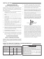
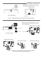
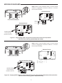
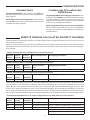
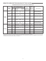
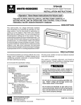
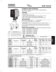
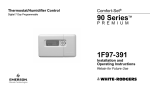
F145-1328/F145-1378
Indoor Remote Sensor/Outdoor Remote Sensor
INSTALLATION INSTRUCTIONS
FAILURE TO READ AND FOLLOW ALL INSTRUCTIONS CAREFULLY
BEFORE INSTALLING OR OPERATING THIS CONTROL COULD CAUSE
PERSONAL INJURY AND/OR PROPERTY DAMAGE.
F145-1328
INDOOR REMOTE SENSOR
F145-1378
OUTDOOR REMOTE SENSOR
Outdoor Probe
Interior Mounting Base
SPECIFICATIONS
Operating Range: (based on thermostat range)
F145-1328 Indoor Model: 40 to 99°F
F145-1378 Outdoor Model: -40 to 140°F
Operating Humidity Range: 0 to 90% RH
(non-condensing)
Maximum Distance from Thermostat: 300 feet
Recommended Wire: 18 or 20 gauge, 3-conductor shielded cable
Color: Classic White
Dimension: 2 1/8" x 3 1/2" x 3/4"
Outdoor Remote includes 12 ft. of outdoor
probe lead
For applications where the wire run is short (100 ft.
or less) shielded cable may not be required provided
the wires are not routed parallel to or across other
wires carrying electrical power. To reduce electrical
interference or inductance from other electrical wiring or devices use shielded cable and keep Remote
Sensor wire runs separate from thermostat wiring.
Remote sensors cannot be used with systems where
power interruptions are part of normal system operation. Compatible with all White-Rodgers remote
sensing thermostats.
! CAUTION
CONTENTS
Specifications................................................. 1
Installation..................................................... 2
Remote Sensor Terminal Cross Reference....... 2
Wiring F145-1328 (Single Stage)......................3
Wiring F145-1328, F145-1378 (Multi-Stage).... 3
Wiring 1F97-1277 (Blue Touchscreen)..............4
Wiring 1F95-1277 (Blue Touchscreen)............. 4
Configuration..................................................5
Remote Sensor Calculated Priority Average......5
Maximum Sensing Locations
Per Thermostat (Chart)...................................6
Troubleshooting................................................7
To prevent electrical shock and/or equipment
damage, disconnect electric power to system
at main fuse or circuit breaker box until installation is complete.
!
WARNING
Do not use on circuits exceeding specified
voltage. Higher voltage will damage control
and could cause shock or fire hazard.
Do not short out terminals on gas valve or primary control to test. Short or incorrect wiring will
damage thermostat and could cause personal
injury and/or property damage.
www.white-rodgers.com
www.emersonclimate.com
PART NO. 37-6606C
Replaces 37-6606B
1319
INSTALLATION
INDOOR SENSOR
1. The interior mounting base can be located a
maximum of 300 feet from the thermostat.
2. Install the interior mounting base within 12 ft.
of the intended outdoor probe location.
3. Never install the outdoor probe where it will be
exposed to direct light from lamps, sun, fireplaces or any temperature radiating equipment.
4. Make sure there are no pipes or ductwork in the
wall chosen for the base location.
5. Outdoor temperature measurement requires
installing the probe outdoors. Good probe locations would be under a bay window or overhang,
out of direct sunlight. Direct sun exposure will
affect sensed temperature. Install probe with
spacer to obtain a more accurate temperature.
SELECT SENSOR LOCATION
Proper location insures that the remote sensor will
provide a comfortable home or building temperature. Observe the following general rules when
selecting a location:
1. The remote sensor can be located a maximum
of 300 feet from the thermostat.
2. Locate sensor about 5 ft. above the room floor
level.
3. Install sensor on a partitioning wall, not on an
outside wall.
4. Never expose sensor to direct light from lamps,
sun, fireplaces or any temperature radiating
equipment.
5. Avoid locations close to windows, adjoining
outside walls, or doors that lead outside.
6. Avoid locations close to air registers or in the
direct path of air from them.
7. Make sure there are no pipes or duct work in that
part of the wall chosen for the sensor location.
8. Never locate sensor in a room that is normally
warmer or cooler than the rest of the home
(such as the kitchen) or building.
9. Avoid locations with poor air circulation, such
as behind doors or in alcoves.
10. In the home, the living or dining room is normally
a good location, provided there is no cooking
range or refrigerator on opposite side of wall.
Spacer
Mounting
Surface
6. Although connected to the probe wire for outdoor temperature sensing, the interior mounting base must be placed indoors. Therefore, the
interior mounting base must be installed near
the perimeter of the building, so that the probe
wire can be run through to the outside of the
structure and placed in the selected (shaded)
location. The outdoor probe wire is 12 feet
long (and should not be cut or spliced), so plan
the placement of both the probe and interior
mounting base accordingly. Any excess wire
may be coiled or bundled. The probe should be
connected to E2 as shown in figure 2.
OUTDOOR SENSOR
SELECT SENSOR LOCATION
Proper location insures that the remote sensor will
provide a correct outdoor temperature reading.
Observe the following general rules when selecting
a location:
REMOTE SENSOR TERMINAL CROSS REFERENCE
Old/New Remote Terminal Designations
Model Number
*F145-1049,
*F145-1170
F145-1328,
F145-1378
! CAUTION
Terminal Designation
S1
S2
S3
+
S
-
Sensor
Positive
Sensor
Return
Signal
Sensor
Negative
Do not allow the 3-conductor wire to be pinched
between the sensor and the wall.
Check wire connections before applying power.
Improper connections will lead to permanent
damage to the sensor.
When shielded cable is used, cable shield
must be connected to "-" or S3 on the
THERMOSTAT ONLY.
*Models no longer available
2
WIRING DIAGRAMS
Note: When using shielded cable, connect
shield of 18 or 20 gauge 3 connector cable
to - or S3 on thermostat subbase.
Remote Sensor
Thermostat Subbase
Figure 1 – Single Stage Thermostat Remote Sensor Wiring (F145-1328)
Note: When using shielded cable, connect shield
of 18 or 20 gauge 3 connector cable to - or S3 on
thermostat subbase.
Remote Outdoor Sensor Base
SA SB SC OT
+ Terminals
L PH D SA SB SC OT
- Terminals
E
C
R W3 W2 E2 W1 Y2 Y1 B
A1
P
O
E2
Outdoor Probe
+
S
–
G
Thermostat Subbase
To +
To OT
To -
Remote Indoor Sensor A
Remote Indoor Sensor B
E2
E2
+
S
+
S
Remote Indoor Sensor C
–
E2
+
–
To To SB
To To SA
To +
To +
To SC
To -
To +
Figure 2 – Staging Thermostat Multi-Stage or Heat Pump Indoor/Outdoor
Remote Sensor Wiring (F145-1328/F145-1378)
3
S
–
WIRING DIAGRAMS
Note: When using shielded cable, connect shield
of 18 or 20 gauge 3 connector cable to - or S3 on
thermostat subbase.
Remote Sensor
E2
+
S
–
Thermostat Subbase
To + or
To S or
To - or
Remote Sensor
E2
Outdoor Probe
If connecting
outdoor service
+
To S1
To S2
To S3
–
S
To +
To OT
To -
Figure 3 – Single Stage (1F97-1277) Touchscreen Thermostat Indoor/Outdoor
Remote Sensor Wiring (F145-1328/F145-1378)
Note: When using shielded cable, connect shield
of 18 or 20 gauge 3 connector cable to - or S3 on
thermostat subbase.
Remote Sensor
Thermostat Subbase
Remote Outdoor Sensor
E2
Outdoor Probe
If connecting
outdoor service
+
S
–
To +
To OT
To -
Figure 4 – Staging Multi-Stage or Heat Pump Touchscreen Thermostat (1F95-1277) Indoor/Outdoor
Remote Sensor Wiring (F145-1328/F145-1378)
4
CONFIGURATION
Comfort-Set II
Comfort-Set III/Comfort-Set
90/90 Series
Single Stage Models: Verify jumper wire W-22 on
the back of the thermostat (not the subbase) has
been clipped.
Single Stage Models(excluding touchscreen): Verify jumper wire W-922 on the back of the thermostat
(not the subbase) has been clipped. You must also
enable the remote sensor option in the Installation
Instructions, Configuration Menu.
Multi-Stage and Heat Pump Models: Verify jumper
wire W-18 on the back of the thermostat (not the
subbase) has been clipped.
Multi-Stage/Heat Pump andTouchscreen Models:
When installing a remote sensor you must enable the
remote sensor option in the Installation Instructions,
Installer Menu.
REMOTE SENSOR CALCULATED PRIORITY AVERAGE
Consult Maximum Sensing Locations Per Thermostat chart on page 6 to determine how many sensors a
thermostat will accept.
Tables 1-3 show how priority (LO, AVG, HI) effects the room temperature calculation. The example below
table three shows the calculation of each remote sensor and how it uses them to arrive at room temperature average.
Table 1: Remote Sensor A configured as a LO priority sensor
Remote Sensor Priority
Room Temperature Averaging Calculation
Sensor Priority Multiplier
SA
LO
1
70°F (Sensor Temp.) 1 x 70 = 70 (Priority Multiplier x Room Temp.)
Table 2: Remote Sensor A configured as a LO priority sensor
Remote Sensor
Priority
Room TemperaAveraging Calculation
Sensor Priority
Multiplier ture
SB
AVERAGE 2
75°F (Sensor Temp.) 2 x 75 = 150 (Priority Multiplier x Room Temp.)
Table 3: Remote Sensor A configured as a LO priority sensor
Remote Sensor
Priority
Room Temperature Averaging Calculation
Sensor Priority
Multiplier
Sc
HI
4
80°F (Sensor Temp.) 4 x 80 = 320 (Priority Multiplier x Room Temp.)
The example below lists three sensors each with a different priority and room temperature. All three sensors
are combined in the calculation to display the average temperature. The priority multiplier shown in the
tables above causes a sensor with low priority to carry less weight in the calculated average. A sensor with
a HI priority setting contributes more to the calculated average. Assume that the building in which the
thermostat is located has three indoor remote sensors (SA, SB, SC) that have different room temperatures
(70, 75, 80). The calculated average will be displayed as the room temperature shown in the example below.
Example: Remote Sensors A, B, and C configured as a LO, AVG, and HI priority sensors
Remote
Sensor
SA
SB
SC
Sensor
Priority
LO
AVERAGE
HI
Priority
Multiplier
1
2
4
Room Temperature Averaging Calculation
70°F (Sensor Temp.) 1 x 70 = 70 (Priority Multiplier x Room Temp.)
75°F (Sensor Temp.) 2 x 75 = 150 (Priority Multiplier x Room Temp.)
80°F (Sensor Temp.) 4 x 80 = 320 (Priority Multiplier x Room Temp.)
Avg. Calc. (540)/Sum Priority Mult. (7)
540/7 = 77°F (Calculated Displayed Temp.)
5
REMOTE SENSOR TROUBLESHOOTING GUIDE
MAXIMUM SENSING LOCATIONS PER THERMOSTAT
Remote
Indoor Sensing Locations
Thermostat
Sensor
Thermostat
Model
Priority
Total
Remote
Onboard
Number
(Max.)
Sensor Assignment
Sensor
(LO/AVG/HI)
Single
Stage
Allows
Outdoor
Remote
Sensor
Sensor Set Up
1F90-371
1
OFF*
With
1*
-
-
Clip Jumper W922 and
Enable Sensor in Menu
1F96-344
1
OFF*
With
1*
-
-
Clip Jumper W922 and
Enable Sensor in Menu
1F97-1277
(Blue)
2
ON or OFF
+
1*
Yes
Yes**
Enable Sensor in Menu
1F97-371
1
OFF*
With
1*
-
-
Clip Jumper W922 and
Enable Sensor in Menu
1F97-391
1
OFF*
With
1*
-
-
Clip Jumper W922 and
Enable Sensor in Menu
1F93-380
4
ON or OFF
+
Up to 3
Yes**
Yes
Enable Sensor in Menu
1F94-371
4
ON or OFF
+
Up to 3
Yes**
Yes
Enable Sensor in Menu
2
ON or OFF
+
1
Yes
Yes** *
Enable Sensor in Menu
1F95-1277
Staging (Blue)
1F95-371
4
ON or OFF
+
Up to 3
Yes**
Yes
Enable Sensor in Menu
1F95-377
4
ON or OFF
+
Up to 3
Yes**
Yes
Enable Sensor in Menu
1F95-391
4
ON or OFF
+
Up to 3
Yes**
Yes
Enable Sensor in Menu
*Using a remote sensor on this model requires the onboard thermostat sensor to be off.
**Allows a sensor priority of LO, AVG., or HI to be assigned to the onboard thermostat sensor in addition to remote sensors
***Accepts one remote sensor, Indoor or Outdoor.
6
TROUBLESHOOTING
To function correctly and read temperature accurately, the thermostat must have constant 24-volt power. If the thermostat temperature is steadily dropping, reading low, or reads 08° when a remote sensor is
installed, it can be traced to one of the three following conditions.
Condition
1. Loss of 24-volt
power.
Test
On models with batteries, remove
the batteries and re-install thermostat. If the display is blank,
check heating and cooling system
to determine why 24-volt power is
absent.
2. A broken wire on
S1, S2 and S3 or
(+, SA, -) from the
thermostat to the
remote.
Disconnect sensor wires at thermostat. Attach a short piece (2')
of three-wire shielded cable to
S1, S2 and S3 or (+, SA, -) on the
subbase. Bring the remote sensor
to the thermostat location and
attach S1, S2 and S3 or (+, S, -)
respectively. Reattach thermostat.
If the temperature begins to climb
(slowly), it is reading correctly. If it
reads correctly with the 2' length
but improperly when attached to
the wire run, it indicates a fault in
the wire run.
Replace remote sensor.
Because it is an electronic sensor,
there are no Ohm values to test. If
correct conditions as listed in 1 & 2
above and the temperature stays at
or near 08°, it indicates a shorted or
damaged remote sensor.
3. A shorted or
damaged remote
sensor.
Comments
For the sensor to read correctly, the
24-volt system power must be present.
Some systems may require an isolation
relay to provide constant power to the
thermostat. Limit or safety devices in
the equipment can also cause a power
interruption.
Repair or replace the 3 wire shielded
cable. Be sure the remote wire run is
not parallel to line voltage wires that
carry heavy inductive loads, or across
fluorescent light ballasts that may
cause an inductance to be transmitted
to the thermostat.
Note: Digital thermostats and remote sensors acclimate very slowly to temperature change. It may take
an hour or more for the temperature to acclimate to the room temperature from a low temperature
reading as outlined above. To expedite the room temperature display use the reset instructions listed in
the installation instructions for the thermostat model you are working with. When reset, the thermostat
will default to a room temperature of 70° and begin sensing room temperature. Be sure to reconfigure
the installer menu for a remote sensor because the reset function may cancel remote sensing.
7
White-Rodgers is a business
of Emerson Electric Co.
The Emerson logo is a
trademark and service mark
of Emerson Electric Co.
www.white-rodgers.com
www.emersonclimate.com