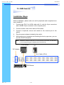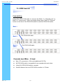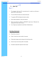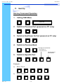
1
User
Manual
CV-401 / 801 / 1601
1U Rackmount PS/2 KVM Switch
CV-401 / CV-801 / CV-1601
User Manual
1.
Table Of Content
1. Table of Content
P.1
2. Introduction
P.2
3. Features
P.2
4. Package Content
P.3
5. Optional Accessories
P.4
6. Peripheral Products
P.4
7. Important Safeguards
P.5
8. Structure Diagram
P.6
9. Dimension Diagram
P.7
10. KVM Session
Front View
Rear View
Installation Steps
Cascading
P.8
P.9
P.10
P.11
11. Start Up
P.12
HotKey Command
HotKey Command Operation
P.12
P.13-14
KVM On Screen Display Control
OSD Structure Diagram
OSD Menu Operation
Rev. : 1.0
P.15
P.16
12. FAQ
P.17
13. Technical Specification
P.18
P.1
CV-401 / CV-801 / CV-1601
User Manual
2.
Introduction
As the server density increases, you run out of spaces in racks and server
room quickly. CV Series PS/2 KVM Switch is slim 1U form factor to provide
effective assistant for an administrator to control multiple PCs
All model are OSD(On-Screen-Display) menu equipped to simply the server
management. It fit different applications and can be cascaded together
expanding the capacity up to 128 computers, and providing the maximum
flexibility.
3.
Features
●
Multi-platform -
Mix PCs, SUN Microsystems, IBM compatibles,
HP, Compaq and Dell.
●
Hot pluggable -
Add PCs or remove connected PCs for
maintenance without powering down the PS/2
KVM switch or PCs.
●
No S/W required -
Easy PC selection via on screen display manual,
push buttons and hot-key.
●
Built-in microprocessor emulation for each port boots up process.
●
High video quality with up to 1,920 x 1,440 and 200MHz bandwidth.
●
Name servers up to 16 characters long.
●
Scan mode with Monitor servers at intervals 5 to 99 seconds.
●
Support eight characters password protection and search PC server
name.
●
VGA, keyboard & mouse all-in-one by 15pin HDDB connector at KVM
side.
●
Cascade for use up to 128 servers.
Disclaimer
This information is subject to change without notice. The producer of this manual accepts no
responsibility for damage or claims, resulting from misuse or misinterpretation
Rev. : 1.0
P.2
CV-401 / CV-801 / CV-1601
User Manual
4.
Package Contents
PS/2 KVM Switch
1 Piece
User Manual
1 Piece
DC Power Adapter
19” Mounting Bracket
1 Piece
1 Pair
Before Unpacking
It is very important to locate the PS/2 KVM switch in a suitable environment.
●
The surface for placing and fixing PS/2 KVM switch should be stable and
level or mounted into a suitable cabinet.
●
Make sure the place is ventilated and out of direct sunlight, away from
sources of excessive dust, dirt, heat, water, moisture and vibration.
●
Convenience for connecting PS/2 KVM switch to the related facilities
should be well considers too.
Unpacking
The PS/2 KVM Switch comes with the standard parts shown as above. Check
and make sure they are included and in good condition. If anything is missing,
or damage, contact the supplier immediately.
Rev. : 1.0
P.3
CV-401 / CV-801 / CV-1601
User Manual
5.
Optional Accessories
KVM Cable
CD-6 / 10 / 15
6ft / 10ft / 15ft PS/2 3-in-1 cable
Cascade Cable
CA-2 / 6 / 10 / 15
2ft / 6ft / 10ft / 15ft PS/2 3-to-3 cable
Conversion Adapter
SUN-31
6.
Rev. : 1.0
SUN / iMAC USB to PS/2 adapter
Peripheral Products
Model
Description
CV-801
8-Port PS/2 KVM switch
CV-1601
16-Port PS/2 KVM switch
CV-101
CAT.5 PS/2 KVM extender
RP115
1U 15” LCD Monitor Drawer
RP 615 / 717 / 819
6U(15") / 7U(17") / 8U(19") LCD Monitor
RK1 / RK2
1U Industrail Keyboard Drawer
RKP115
1U LCD Keyboard Drawer
P.4
CV-401 / CV-801 / CV-1601
User Manual
7.
Important Safeguards
Please read all of these instructions carefully before you use the device.
Save this manual for future reference.
●
Unplug the PS/2 KVM switch from the power outlet before cleaning.
●
Do not spray liquid cleaners or aerosol directly on the device. Wet a cloth with
a neutral detergent (e.g. clean water) and squeeze it tight, then clean the
screen slightly with it.
●
Do not expose the PS/2 KVM switch directly to rain, water, moisture or
sunlight.
●
Do not attempt to service the device yourself. Improper operation may void
your warranty. Refer all servicing to qualified service personnel.
●
●
Safe storage environment of the PS/2 KVM switch is ranging between –20oC
and 60oC. Permanent damage could occur if the PS/2 KVM switch is stored
outside the safe range.
Unplug the keyboard drawer with PS/2 KVM switch immediately and call a
qualified service personnel under the following conditions:
1.
If the PS/2 KVM switch has been exposed to rain, liquid or water.
2.
If the PS/2 KVM switch has been dropped or the casing has been
damaged.
What the warranty does not cover
1.
Any product, on which the serial number has been defaced, modified or
removed.
2.
Damage, deterioration or malfunction resulting from:
a) Accident, misuse, neglect, fire, water, lightning, or other acts of nature,
unauthorized product modification, or failure to follow instructions supplied
with the product.
b) Repair or attempted repair by anyone not authorized by us.
c) Any damage of the product due to shipment.
d) Removal or installation of the product.
e) Causes external to the product, such as electric power fluctuation or failure.
f)
Use of supplies or parts not meeting our specifications.
g) Normal wear and tear.
h) Any other causes which does not relate to a product defect.
3. Removal, installation, and set-up service charges.
Rev. : 1.0
P.5
CV-401 / CV-801 / CV-1601
User Manual
8. Structure Diagram
•
ƒ
„
1. PS/2 KVM Switch
2. Cable Mounting Kit
3. 19” Mounting Kit
4. KVM Membrane
Rev. : 1.0
P.6
‚
CV-401 / CV-801 / CV-1601
User Manual
9. Dimension Diagram
CV-401 / CV-801 / CV-1601
Rev. : 1.0
P.7
CV-401 / CV-801 / CV-1601
User Manual
10. KVM Session
Front View
Bank No.
Selected Channel
Online Channel
Channel Select Button
Bank Button
Shift Button
LED Indication
Selected Channel
- Displayed channel on monitor & red in
LED.
Channel select button - Press to select channel from 1 – 8.
Rev. : 1.0
Shift button
- Press & Hold follow with a channel
button to select channel from 9 – 16.
Online Channel
- Green LED state the PC has
connected and power on.
Bank No..
- Display the Bank no. from 1 – 8.
Bank button
- Select the bank from 1 – 8 (for cascade
only)
P.8
CV-401 / CV-801 / CV-1601
User Manual
10. KVM Session
Rear View
DC
Cascade
Console
Power
Port
Port
Channel
Port
CV-401
CV-801
CV-1601
Rev. : 1.0
DC Power
-connect to external 12V DC power adapter.
Cascade Port
-connect to
expansion.
Console Port
- connect to monitor, PS/2 keyboard & mouse.
Channel Port
- connect to PC computer with CD-6 3-in-1 KVM cable.
P.9
additional
KVM
switch
for
channel
CV-401 / CV-801 / CV-1601
User Manual
10. KVM Session
Installation Steps
Before installation, please make sure all of peripherals and computers have
been turned off.
1.
Connect the CD-6 3-in-1KVM cable with 2 x mini-din 6-pin connectors
and a HDDB 15-pin connector to the computer ports.
2.
Connect another end of the cable to KVM switch.
3.
Connect a keyboard, mouse and monitor to the console port of the
switch.
4.
Plug the power adapter included to the switch.
5.
After powering on computers and finishing the boot-up process, you can
start the PS/2 KVM switch.
Note: Please don’t switch the PC port (i.e. Don’t press the push button of KVM switch
or run hot key) during the computers are under boot-up.
VGA Monitor
PC
DC Adapter
3-in-1 Cable (CD-6)
PS/2 Mouse
PS/2 Keyboard
Rev. : 1.0
P.10
CV-401 / CV-801 / CV-1601
User Manual
10. KVM Session
Cascading
Using CA-6 PS/2 KVM cable to connect from Bank 1’s “Cascade port” to
Bank 2’s “Console port”. After connected please press “Bank” & “Channel”
button on the front of the PS/2 KVM switch to reset the PS/2 KVM switch.
Bank 1
Bank 2
Bank 8
(Max.)
CA-6 PS/2 KVM cable
CA-6 PS/2 KVM cable
Cascade level Max. : 8 level
Rev. : 1.0
●
Max. PC connection is 128 or with additional 122 PCs.
●
All PS/2 KVM switch is compatible & can cascade with each other.
●
Using CA-6 PS/2 KVM cable to cascade.
●
Normal distance from one PS/2 KVM to another is 15 feets.
P.11
CV-401 / CV-801 / CV-1601
User Manual
11. Start Up
1.
The channels that have PC connected and it is switch on will have a
green LED on that channel.
2.
The red LED will indicate the selected channel.
3.
7 segments LED will display the bank number.
4.
Press channel button to select the channel.
5.
Enter the password, default is “00000000” eight zeros. Otherwise the
keyboard & mouse will be locked.
6.
If you forget your password, send back to Manufacturer.
Hot Key Command
Rev. : 1.0
●
Simple key sequence.
●
Press “ Scroll Lock” twice within 2 seconds.
●
Follow with a beep sound, going into the hot key mode.
●
Need to key in the hot key within 2 seconds.
●
Go back to Operation System Control state.
P.12
CV-401 / CV-801 / CV-1601
User Manual
11. Start Up
Hot-key Command Operation
1.
Calling OSD Menu
Scroll
2.
£
+
Scroll
+
¤
+
Switch to Previous Bank
Scroll
5.
Scroll
+
Switch to Next Power On Port (powered on PC only)
Scroll
4.
Space Bar
+
Switch to Previous Port (powered on PC only)
Scroll
3.
Scroll
+
Scroll
+
First digit of Port Number:
0 for Port 0-9
1 for Port 10-16
Second digit of
port Number
Pg
Up
+
Switch to Specific Port
Scroll
Scroll
+
Bank
1~8
+
No.
0 or 1
+
No.
0-9
+
Example :
a)
Bank 1 Port 4
Scroll
b)
Scroll
+
1
+
0
2
+
1
+
4
Bank 2 Port 16
Scroll
Rev. : 1.0
+
+
Scroll
+
P.13
+
6
CV-401 / CV-801 / CV-1601
User Manual
11. Start Up
HotKey Command Operation
6.
Switch to Next Bank
Scroll
7.
+
Scroll
+
PgDn
Enable / Disable beeper sound
Scroll
+
Scroll
B
+
Note: The default Beeper function is ON and beeper control is only for
8.
Auto Scan for Powered on PC
Scroll
9.
+
Scroll
S
+
Reset to factory Default Setting
Scroll
+
Scroll
R
+
ROM REFLASH
Note: Not available for password reset.
10. Find Port by name
Scroll
+
Scroll
F
+
FIND:█
Note: When the above dialogue appear, type the PC name and the OSD Menu
will search PC name starting from 1st powered on PC port.
Rev. : 1.0
P.14
CV-401 / CV-801 / CV-1601
User Manual
11. Start Up
OSD Structure Diagram
Bank Session
BANK : 1
BANK : 1 SYSTEM 01
01
01
03
SYSTEM
01 03
®
SYSTEM
03
05
03
® SYSTEM 05
05
07
® SYSTEM 05
07
02
® SYSTEM 02
E
SYSTEM0204
02 ®®SYSTEM
04
06
06
08
® SYSTEM
SYSTEM0406
PC Session
SYSTEM
06 08
®
SYSTEM
07
® SYSTEM 08
OSD SYSTEM
: 1 0 SEC. 07
CHANGE08PASSWORD
OSD : 1 0 SEC. CHANGE
SCAN:
CONSOLEPASSWORD
ON/OFF
KVM Settings
Session
SCAN:
1 0 SEC. ENTER
CONSOLE
ON/OFF
ESC
: QUIT
:COMPLETE
ESC :: QUIT
TAB
NEXT
ENTER
:COMPLETE
INSERT
:EDIT
Menu
Information
TABSELECT
: NEXT PORT
INSERT :EDIT
á/â:
á/â: SELECTBANK
PORTSELECT
PgDn/PgUp:
PgDn/PgUp: BANK SELECT
OSD Menu Operation
Use “Tab” key to select session like Bank, PC, OSD, SCAN, CHANGE
PASSWORD, CONSOLE ON/OFF, etc…
Bank Session
Use Page Up & Page Down to switch previous or next bank
PC Session
1.
“®” next to the PC name represents the PC system is powered on
2.
Use up arrow key “á” or down arrow key “â” to select port for destination PC name and press “Enter” to select
3.
Edit PC name - Press “Ins” key for editing PC name
Note: PC name should not be more than 8 characters.
4.
Rev. : 1.0
When editing is finished press “Enter”.
P.15
CV-401 / CV-801 / CV-1601
User Manual
11. Start Up
KVM Settings Session
1.
OSD
●
●
2.
●
It can be modified to 99
seconds for maximum.
Choose “Change Password” in
KVM Setting Session.
●
Key-in the existing password.
●
Enter the New Password.
●
Re-Enter the New Password.
●
Changing Password complete.
●
The steps are shown as next
picture:
Console On/OFF
●
ON – any user can use the
console
●
●
5.
Scan interval from one PC port
to next PC port when applying
auto scan, its default is 10
seconds.
Change Password
●
Default password “00000000”
8 zeros
●
4.
It can be modified from 05 – 99
seconds.
Scan
●
3.
OSD Menu on screen time
default is 10 seconds.
OFF – user is not allowed to
use the console port, unless
password is entered.
Default – OFF, you need to
key-in password.
Escape
When the following screen is
appeared, you can press
”ESC” key to escape.
ENTER PASSWORD : █
ESC : QUIT
ENTER :
ENTER NEW PASSWORD : █
ESC : QUIT ENTER : COMPLETE
RETYPE NEW PASSWORD : █
ESC : QUIT ENTER :
COMPLETE
NEW PASSWORD COMPLETE
ESC : QUIT ENTER :
COMPLETE
●
Rev. : 1.0
P.16
102
?SYSTEM 02
CV-401 / CV-801 / CV-1601
User Manual
12. FAQ
1. Don’t press any keys on the keyboard while the selected
computer is booting up. Otherwise, it might cause the
keyboard error or keyboard is not detected at PC side.
2. The computer boot up fine, but keyboard doesn’t work.
●
Make sure the keyboard works when directly plugged into the computer.
●
Try a different keyboard, but use only 101, 102 or 104-key keyboard.
3. The Mouse is not detected during PC boot up.
●
Make sure the mouse works when directly plugged into the computer.
●
Make sure the mouse is a true PS/2 mouse. A combo mouse will work just as long
as it is set for PS/2 mode with the correct adapter. Try a different mouse.
Avoid moving the mouse or pressing the mouse buttons when switching ports.
Avoiding switching ports during shutting down the PC process.
●
●
●
When you switch one PC port to another PC port, the best scan time setting need to
be set to 5 seconds or more. Normally, the VGA monitor change one resolution
mode to another will take one or two seconds. So, the scan time is not
recommended to below 5 seconds.
4. Sun Server connection problem.
PS/2 KVM switch are using standard PS/2 type keyboard, mouse and D-sub 15pin
VGA for connection. If you need to connect Sun Server to PS/2 KVM switch, you need
a separate converter kit.
5. Sun – 31 Kit
●
●
Rev. : 1.0
Convert USB to P/S 2 Keyboard & Mouse.
New model Sun Micro Server are using D-sub 15 pin Standard VGA.
P.17
CV-401 / CV-801 / CV-1601
User Manual
13. Technical Specification
Item
Specification
KVM Channel Port
CV-401: 4 port / CV-801: 8 port / CV-1601: 16 port
KVM Channel Interface
HDDB 15 pin
PS/2 Keyboard: Mini Din 6 pin Female
PC Computer Interface
PS/2 Mouse: Mini Din 6 pin Female
VGA : HDDB 15pin Female
PS/2 Keyboard: Mini Din 6 pin Female
Cascade Port Connector
PS/2 Mouse: Mini Din 6 pin Female
VGA: HDDB 15pin Female
KVM Cable Connection
3-in-one HDDB 15-pin KVM Cable (CD-6 / 10 / 15)
PC selection
On Screen Display, Hot Key & Push Button
LED
Rev. : 1.0
1 Bank LED
4 / 8 / 16 Online LED (Green) & Selected LED (Red)
On Screen Display Control
Yes
Scan Mode Intervals
5~99 Sec.
VGA Resolution
1,920X1,440
Bandwidth
200MHz
Cascade MAX. Level
8 levels with addition 112 PCs connection
Housing
Metal
Power Adapter
DC 12V 1A
Operation Temperature
0~40℃
Storage Temperature
-20 ~ 60℃
Humidity
0~80%, Non-Condensing
Product Dimension
449 W x 44H x 110D mm
Net Weight
CV-401 : 3.5 Kg / CV-801 : 3.5 Kg / CV-1601 : 4 Kg
P.18
Print at 8/2004