1
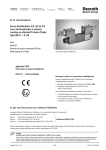
VT-VRPD-2 – Digital valve amplifier for valve types 4WRE 6, component series 2X 4WRE 10, component series 2X Installation and Operation RE 30126-B/09.13 Replaces: 08.07 2/32 Bosch Rexroth AG | Hydraulics Installation and Operation | RE 30126-B/09.13 RE 30126-B/09.13 | Installation and Operation Hydraulics | Bosch Rexroth AG 3/32 Contents 1 General ......................................................................................................5 1.1 About this Manual .......................................................................................5 Additional Documentation ............................................................................................ 5 Characters and Symbols .............................................................................................. 6 1.2 Scope of Supply .........................................................................................7 1.3 Requirements .............................................................................................7 2 Installing the VRPD ..................................................................................8 2.1 Safety Requirements ..................................................................................8 Proper Use ................................................................................................................... 8 Personnel Selection and Qualifications ........................................................................ 9 Design Changes and Electrical Installation .................................................................. 9 2.2 Repair and Troubleshooting .....................................................................10 2.3 Transport, Storage and Handling the Controller Card ...............................11 2.4 Card Installation .......................................................................................12 2.5 Edge Connector Terminals and Pin Assignments .....................................13 2.6 Installation Local Bus................................................................................17 2.7 Connecting the proportional valve ............................................................18 2.8 Connecting the valve position transducer .................................................19 3 Startup of the VRPD Controller Card ....................................................20 3.1 Preparing for Use .....................................................................................20 3.2 Installing BODAC software .......................................................................21 Installation Requirements ........................................................................................... 21 BODAC Setup ............................................................................................................ 21 4/32 Bosch Rexroth AG | Hydraulics Installation and Operation | RE 30126-B/09.13 3.3 Initial startup with BODAC ........................................................................22 4 VRPD Operation .....................................................................................23 4.1 Display/Input Keys and Connectors on the Front Panel ............................23 4.2 Diagnostics Test Jacks .............................................................................24 5 Diagnostics .............................................................................................25 5.1 Diagnostic Options on the VRPD Controller Card .....................................25 5.2 Diagnostics Using BODAC .......................................................................25 6 Detecting Errors .....................................................................................26 6.1 Error Messages ........................................................................................26 6.2 Changing fuses ........................................................................................27 7 Index ........................................................................................................29 RE 30126-B/09.13 | Installation and Operation Hydraulics | Bosch Rexroth AG 5/32 General 1 1 General 1.1 About this Manual Before installing or operating your VRPD Controller card for the first time, you should read this Manual. Please note the safety requirements described in section 2.1. Persons involved with the start-up and operation of the controller card should have proper training on the installation and operation of this type of equipment. This manual is intended to inform you about the functions of this controller card and its intended use. The Manual contains important safety instructions on proper installation and operation of the controller card. Observing these instructions will help you: avoid hazards and dangers minimize repair costs and downtime increase the useful life and reliability of the controller card Additionally, please observe all regulations that are in effect in the country and/or community to prevent accidents and to protect the environment. This manual only describes the installation and operation of the controller card. Information about starting up the controller card using BODAC software is located in a separate document: “Operation of the BODAC Software and Starting up the VRPD Control Card”. A list of documentation for the VRPD can be found in the “Additional Documentation" section. Additional Documentation Additional information to this document “VRPD Digital Control for Electro-mechanical and Electro-hydraulic Drives is available. It contains: RE sheet "RE 30 126" in paper form. Document “ RE 30 126-B " Starting up the VRPD Control Card and Operation of the BODAC Software ". Internet: http://www.boschrexroth.com/HACD 6/32 Bosch Rexroth AG | Hydraulics Installation and Operation | RE 30126-B/09.13 1 General Characters and Symbols The following characters and symbols are used in the manual: ¾ Action symbol: The text following this symbol describes actions. These should be performed, from top to bottom, in the given order. 9 Result symbol: The text following this symbol describes the results of an action. Following this symbol you will find notes and useful tips for optimal use of the controller card.. Warning symbols Special safety notes are provided at the relevant locations. These are indicated by the following symbols. General hazard potential Indicates a potentially hazardous condition which, if not avoided, could result in death or serious injury If the hazard source can be specifically indicated, the corresponding pictogram will be used. Electrical current hazard This symbol refers to a hazardous condition caused by electrical current which, if not avoided, could result in death or serious injury. Equipment damage This symbol pertains to actions which could result in damage to equipment. RE 30126-B/09.13 | Installation and Operation Hydraulics | Bosch Rexroth AG 7/32 General 1 1.2 Scope of Supply The equipment is packed in anti-static packaging to protect the controller card from electrostatic discharge. Observe instructions on the top side of the packaging. Included in the shipment: 1.3 Controller Card VRPD RE sheet RE 30 126-B Requirements Mounting the controller card in a card holder VT 3002-2x/G64 described in datasheet RE 29 928. The card holder should be used only inside a control cabinet, as there is no protection from accidental contact. If no power is provided by the user, the following power supply is available as an option: VT-NE30 described in datasheet RE 29 929. 8/32 Bosch Rexroth AG | Hydraulics Installation and Operation | RE 30126-B/09.13 2 Installing the VRPD 2 Installing the VRPD 2.1 Safety Requirements Operate the VRPD controller card only if it is not damaged and is in proper operating condition and is applied for its intended purpose. Observe all safety and hazard instructions in the included documentation. When faults occur, which compromise safety and result in changes in operating conditions, shut down the controller card immediately and notify responsible personnel. Fault free and safe running of the controller card assumes appropriate transport, storage and installation, as well as proper startup and operation. The VRPD Control Card has been built using the latest technology, and in accordance with recognized safety standards. Nevertheless, operation may result in hazard to persons or property if: The VRPD Controller Card is not used properly. The VRPD Control Card is not installed, commissioned and operated by qualified persons. Changes or modifications are made to the VRPD controller card. Safety requirements and safety notes are not observed. The VRPD controller card is intended for industrial use. The card must not be operated until it has been determined that the system in which the controller card is installed, meets all applicable standards and safety regulations for the application. In European countries: EC Directive 89/392/EWG (Machine Directive) Operation is permitted only when applicable EMC regulations for the application are met. Adherence to limits defined by regulations and standards are the responsibility of the manufacturer of the system or machine. In European countries: EC Directive 89/336/EWG (EMC Directive) In the United States: National Electrical Code (NEC) and National Electrical Manufacturers Association (NEMA), as well as local standards should be observed. The operator is required to adhere to the above named standards at all times. Proper Use The VRPD is designed to control Electromechanical and Electrohydraulic Drives. Possible application area’s are: Valve Amplifiers Proper use requires adherence to the manuals and supplementary documentation, and observing relevant safety and operating standards. RE 30126-B/09.13 | Installation and Operation Hydraulics | Bosch Rexroth AG 9/32 Installing the VRPD 2 Personnel Selection and Qualifications Operation and Startup Operation and startup of the VRPD controller card requires specialized skills. Therefore this work should be performed only by properly trained individuals. Only persons who are trained or properly instructed should start up and operate the VRPD controller card. Additionally the oversight of a qualified supervisor may be advised. Personnel are considered qualified if they are familiar with the installation, startup and operation of the VRPD controller card, and with all the warning notes and safety regulations contained in the accompanying documentation. Work on the electrical equipment must be performed only by qualified specialists or by personnel appropriately instructed and under the supervision and guidance of persons qualified and familiar with electrical safety standards. An electrical specialist is someone who, based on his technical knowledge and training, as well as knowledge of the relevant standards, is able to evaluate the tasks assigned to him, recognize potential hazards and take the appropriate safety measures. Repair and troubleshooting Repair and troubleshooting requires specialized skills. Therefore, this work should be performed only by trained and designated specialists. Design Changes and Electrical Installation User changes to the VRPD controller card may result in safety hazards. Note the following recommendations on electrical installation: Use low-capacitance cables. Make cable connections without intermediate connections whenever possible. Control electronics should be isolated from electromagnetic noise sources (IE: V/F drives). Power wiring should not be routed in the vicinity of control electronics. Power wiring should not be routed in the vicinity of control wiring or cables. Route sensor lines separately. Maintain a distance of at least 1 meter from antenna lines, RF devices and radio equipment. When using differential inputs switch both inputs on and off at the same time. When switching signal inputs, use dry circuit rated relays with gold-plated contacts (low voltages, low currents) Always shield all analog signal lines. Connect shields at the card end only, connecting to the "Shield" terminal, and leave the other end open to prevent ground loops. Connect to an appropriate system ground using stranded copper wire (min 2 2.5mm / 12 AWG) The system ground is an essential component of the EMC protection for the controller card. The ground provides a path for noise that could otherwise enter the controller card through the signal and power supply lines. Noise is bypassed only if the sys-tem ground does not couple noise into the controller card. 10/32 Bosch Rexroth AG | Hydraulics Installation and Operation | RE 30126-B/09.13 2 Installing the VRPD 2.2 Bosch Rexroth also recommends shielding solenoid wiring. Do not use logical signals from the controller card (IE: “OK” signal) for switching machine safety circuits (see European Norm "Safety Requirements for Fluid Power Systems and Components" EN982:1996). Repair and Troubleshooting If the control cabinet contains additional electrical components utilizing high voltage, always observe safety standards to prevent accidents! Use appropriate protective gear, such as safety shoes and safety gloves, when prudent! Use appropriate tools (IE: insulated tools) Before opening control cabinet doors, open the main disconnect. To ensure safe working conditions, observe the following safety rules: Remove all power Ensure against unintended energization: lockout devices when possible, and use lockout warning tags Verify that voltage is not present Cover or close off adjacent areas that are still energized. If work on energized components is necessary, have a second per-son present as a safety backup to actuate an E-STOP switch or open the main disconnect, if necessary. Use insulated tools only. RE 30126-B/09.13 | Installation and Operation Hydraulics | Bosch Rexroth AG 11/32 Installing the VRPD 2 2.3 Transport, Storage and Handling the Controller Card The packaging contains notes on handling of the controller card. These must be strictly followed. SDLC ATTENTION Static Sensitive Devices ATTENTION Circuits sensibles à l' électricité statique. ACHTUNG Elektrostatisch gefährdete Bauelemente. Manipulation uniquement Handhabung daher nur an Handle only at Static Safe Work autorisée sur un poste de geschützten Arbeitsplätzen erlaubt. travail protégé. Stations HACD_HW_DE_2-1 Fig. 1 Notes for handling printed on the packaging Observe the following: Keep the controller card away from moisture and dust Observe the allowable storage temperature range of –20° C to +70 °C. (allowable operating temperature: 0 – 50° C) Electrostatic discharge (ESD) can damage components on the controller card. To prevent damage, observe the following recommendations. Discharge static voltage from your body using accepted practices. Work in a safe environment. Do not use any devices in the working environment that generate or hold static charge. Avoid working with the controller card in areas where floors or work surfaces is composed of materials that can generate a static charge. Handle the controller card carefully. Do not touch any exposed pins or electronic components. Transport and store the control card in its original packaging. 12/32 Bosch Rexroth AG | Hydraulics Installation and Operation | RE 30126-B/09.13 2 Installing the VRPD 2.4 Card Installation Remove the card from its packaging only at a protected work place. Do not touch any electrical components when placing the controller card in its proper card holder as shown in Fig. 2. Correctly installing the VRPD controller card: ¾ Remove power from the rack when installing the card. ¾ Hold the card by the front panel and remove it from the packaging. ¾ Slide the card into the guide rails of the rack without using excessive force, as shown in Fig. 2 Installing the controller card. ¾ Snap the edge connector in place by gently pressing on the front panel. card male connector mounting screws guide rails Faceplate HACD_HW_EN_2-2 Fig. 2 Installing the controller card ¾ Tighten the two mounting screws on the front panel. 9 The card is now installed correctly. RE 30126-B/09.13 | Installation and Operation Hydraulics | Bosch Rexroth AG 13/32 Installing the VRPD 2 2.5 Edge Connector Terminals and Pin Assignments The edge connector is a 64-pin, Type G (DIN 41612). The pin assignments for the edge connector are not fully downward compatible with older amplifier products. Differences in pin assignments have been implemented such that damage is prevented if an old controller card (VT 12350-3x or VT 12352-3x) is replaced by a VRPD controller card. Row d Pin Description Type 2 DI 1 Discrete input 4 DI 2 Discrete input 6 DI 3 Discrete input 8 DI 4 Discrete input 10 DI 5 n. c. 12 DI 6 Discrete input 14 DI 7 n. c. 16 DI 8 n. c. 18 DI 9 Discrete input 20 DO 1 Discrete output 22 OK Discrete output 24 Data + Local CAN Bus Input/Output 26 DO 2 Discrete output 28 Data – Local CAN Bus Input/Output 30 AO 1 Analog output 32 AO 2 n. c. Tab. 1 Pin assignment of edge connector Row d 14/32 Bosch Rexroth AG | Hydraulics Installation and Operation | RE 30126-B/09.13 2 Installing the VRPD Row b Pin Description Type 2 AI3+ n. c. 4 AI3- n. c. 6 AI2+ Differential input 8 AI2- Differential input 10 AI1+ n. c. 12 AI1- n. c. 14 AI4+ Differential input 16 AI4- Differential input 18 AI5+ Differential input 20 AI5- Differential input 22 AI6+ Differential input 24 AI6- Differential input 26 AO3 Analog Output 28 AGND Analog GND 30 REF- Reference voltage -10V 32 REF+ Reference voltage +10V Tab. 2 Pin assignment of edge connector Row b RE 30126-B/09.13 | Installation and Operation Hydraulics | Bosch Rexroth AG 15/32 Installing the VRPD 2 Row z Pin Description Type 2 MA+ Solenoid a + 4 MA- Solenoid a - 6 MB+ Solenoid b + 8 MB - Solenoid b - 10 Shield Shield 12 L1O- LVDT valve pin 2 14 L1I- LVDT valve pin 4 16 L1I+ LVDT valve pin 3 18 L1O+ LVDT valve pin 1 20 Ground System ground 22 DO 3 Discrete output 24 DO 4 Discrete output 26 DO 5 Discrete output 28 DO 6 Discrete output 30 UB Supply voltage 32 LO Supply GND Tab. 3 Pin assignment of edge connector Row z 16/32 Bosch Rexroth AG | Hydraulics Installation and Operation | RE 30126-B/09.13 2 Installing the VRPD Row f Pin Description Type 2 DO 7 n. c. 4 SSI Clk + n. c. 6 SSI Clk - n. c. 8 AI7+ n. c. 10 AI7- n. c. 12 Ua2 n. c. 14 /Ua2 n. c. 16 Ua0 n. c. 18 /Ua0 n. c. 20 L2O- n. c. 22 L2I- n. c. 24 L2I+ n. c. 26 L2O+ n. c. 28 GND_CAN n. c. 30 CANL n. c. 32 CANH n. c. Tab. 4 Pin assignment of edge connector Row f RE 30126-B/09.13 | Installation and Operation Hydraulics | Bosch Rexroth AG 17/32 Installing the VRPD 2 2.6 Installation Local Bus The local bus is used to connect the individual amplifier cards of the HACD family. Up to 32 cards can be connected. Each amplifier must be assigned a clear bus address. The connection is established using a CAN protocol with a baud rate of 250kbit. The maximum length of the most distant amplifier cards must not exceed 280m. Moreover, the maximum length of the branch lines of 1 m must be observed. Fig. 3 Schematic structure of “Local Bus“ Data is to be transmitted via a shielded twisted-pair cable. Two bus terminating resistors of 120 Ohm are required. 18/32 Bosch Rexroth AG | Hydraulics Installation and Operation | RE 30126-B/09.13 2 Installing the VRPD 2.7 Connecting the proportional valve When connecting the proportional valve, be sure that the solenoid cables are routed separately from the inductive position transducers. It is strongly recommended that the solenoid cable is shielded. For lengths up to 50 m cable 2 x 1.5 mm² of type LiYCY-CY (16 AWG double-shielded cable) is recommended. When double shielded cable is used the outer shield can be terminated entering the control cabinet and the inner shield needs to be terminated at the controller card. Solenoid connector wiring Solenoid a Solenoid b PE PE 1 1 2 to Controller z10 z2 2 to Controller z4 z6 z8 VPCD_05 Fig. 4 Connecting the solenoids A CECc 75301-803-A002FA-H3008-G cable connector according to DIN EN 175 301803 and ISO 4400 is recommended for connecting the solenoids. Solenoid a, cable connector color gray Order separately under material number R901017010 Solenoid b, cable connector color black Order separately under material number R901017011 Single-solenoid valves are to be connected to solenoid A+/A-. The solenoid B+/B- connection then remains open. For single-solenoid valves, only positive command values are recognized as being valid. When using single-solenoid valves in conjunction with current input b22/b24, it must be noted that range +/-100% is set as default setting. To be able to utilize the full range 0…20mA, range 0~100% must be set. RE 30126-B/09.13 | Installation and Operation Hydraulics | Bosch Rexroth AG 19/32 Installing the VRPD 2 2.8 Connecting the valve position transducer Connection for the valve position transducer is shown in the following illustration. Valve position feedback connection 4 2 1 3 z14 z12 z16 z18 z10 VPCD_06 Fig. 5 Connecting the valve transducer The transducer is connected using a 4-pole cable connector Pg7-G5W1F, which can be ordered separately under material number R900023126. Cable 4 x 0.25 mm² of type LiYCY-CY ( 4 x 30 AWG Double shielded cable) is recommended for lengths up to 50 m. The shield should be connected to z10 on the edge connector of the controller on the supply side only. 20/32 Bosch Rexroth AG | Hydraulics Installation and Operation | RE 30126-B/09.13 3 Startup of the VRPD Controller Card 3 Startup of the VRPD Controller Card 3.1 Preparing for Use The startup procedure for the VRPD controller card depends on a variety of factors that are determined by the individual application. For this reason, only the basic startup steps are described in this manual. Preparing the controller card for use: ¾ Carefully check cabling. ¾ Apply power to the VRPD controller card. Fig. 6 Front panel of the VRPD Controller Card 9 The controller card performs an internal function test. 9 The display on the controller card shows the manufacturer name and version number in scrolling text (when powered up) RE 30126-B/09.13 | Installation and Operation Hydraulics | Bosch Rexroth AG 21/32 Startup of the VRPD Controller Card 3 3.2 Installing BODAC software BODAC software (ordering code SYS-HACD-BODAC-01 ordering number R900777335) can download via Internet (www.boschrexroth.com/hacd). This software is used for initial startup and as a convenient configuration and monitoring tool for the controller card. BODAC can be used to configure the settings and parameters for optimal operation of the VRPD controller card. The connected VRPD card configures the function, menus and program windows in BODAC. This makes using the software easy. Installation Requirements Hardware Software 100% IBM compatible PC with the following minimum requirements: 200 MHz Pentium processor (or equivalent) 32 MB working memory (RAM) VGA graphics card, minimum resolution: 800x600 pixels Hard drive with minimum 2 MB available space CD-ROM drive Mouse Available serial port Operating system: Windows 2000 / XP. If the hardware/software requirements are met, you can install BODAC as described in the next section. BODAC Setup To start the installation of BODAC, execute the “Setup.exe“ file. Installing BODAC software: ¾ Insert the CD-ROM and locate the file “Setup.exe“. ¾ Double-click on “Setup.exe“. 9 The setup program will load and display a start screen. ¾ To run Setup, follow the instructions on the screen. 9 BODAC software will then be installed. 22/32 Bosch Rexroth AG | Hydraulics Installation and Operation | RE 30126-B/09.13 3 Startup of the VRPD Controller Card 3.3 Initial startup with BODAC After installing the VRPD controller card in a rack, as described in section 2.4 "Card Installation", and all initial steps have been completed properly, the card startup is ready. Before proceeding with the following steps, be sure that the following requirements have been met: Serial interface cable is available A serial port on the PC is available BODAC software is installed. Proceed with the initial startup: ¾ Connect serial cable (ordering number R900776897) to the connector on the VRPD card. ¾ Plug serial cable into the serial port (COM) on the PC (or use USB-converter – S/N R90166684). 9 The VRPD card and PC are now connected. ¾ Start the BODAC software. ¾ Perform the software-side startup as described in the “Starting up the VRPD Control Card and Operation of the BODAC Soft-ware” document. RE 30126-B/09.13 | Installation and Operation Hydraulics | Bosch Rexroth AG 23/32 VRPD Operation 4 4 VRPD Operation 4.1 Display/Input Keys and Connectors on the Front Panel You can use the display, input keys and connectors on the front panel of the VRPD to check parameters and settings, attach diagnostic instruments and connect the card to a PC. The following illustration shows an overview of the display, input keys and connectors on the front panel. Fig. 7 Display, input keys and connectors on the control card LEDs for Discrete I/O The input LEDs indicate the state of the discrete input signals. The output LEDs show the state of discrete outputs from the controller card. When a signal is present on a discrete I/O, the associated LED will illuminate. 24/32 Bosch Rexroth AG | Hydraulics Installation and Operation | RE 30126-B/09.13 4 VRPD Operation Serial port 4.2 The serial port on the front panel is configured as a standard RS-232 port using a 9pin D-Sub female connector. A standard 9 pin serial data cable is used to connect the serial port to a PC. Diagnostics Test Jacks The diagnostic test jacks on the front panel of the card can be used to connect external test instruments. Two analog voltage signals are available to perform measurements. RE 30126-B/09.13 | Installation and Operation Hydraulics | Bosch Rexroth AG 25/32 Diagnostics 5 5 Diagnostics 5.1 Diagnostic Options on the VRPD Controller Card Diagnostics terminal Diagnostics test jack "X1" Diagnostics test jack "X2" 5.2 The diagnostic test jacks on the front panel of the VRPD controller card (see section 4.1 Display/Input Keys and Connectors on the Front Panel, Fig. 7 ) provide two analog outputs with the following ratings: X1, 10 Volts for test equipment having Ri 100 k: ) X2, 10 Volts for test equipment having Ri 100 k: ) COM, ground Here, you can select the signal to be measured. The following signals can be output: Pressure command value, swivel angle command value, power command value, actual valve value, actual pressure value, and actual swivel angle value. Diagnostics Using BODAC The BODAC software includes additional detailed diagnostics capabilities. The “Motion Data” screen and the “Status” screen display the current status of the controller card and of the connected sensors and devices. Motion Data Screen Status Screen The Motion Data screen displays the internal control signal values in the controller card. This provides a quick overview of the process status and values. The Status screen is used to display the status of the controller card. Each entry will display either “OK”, “WARNING” or “ERROR" as a value. For additional information on the Motion Data screen and the Status screen, refer to document "Starting up the VRPD Control Card and Operation of the BODAC Software". 26/32 Bosch Rexroth AG | Hydraulics Installation and Operation | RE 30126-B/09.13 6 Detecting Errors 6 Detecting Errors 6.1 Error Messages Error message Description +/- 10V Source Reference voltage +10V (b32) or Reference voltage –10V (b30) outside the specified range. Power 24V Power supply Ub (z30) less than Ub min. DO1~DO7, „OK“ Short Short circuit of one or more of the 8 digital outputs. Memory Checksum Checksum error in Program- or Parameter memory (Flash or EEprom) Memory error Error in Memory (RAM) Version mismatch Version Mismatch between the internal software Analog Input AI2 The value of the analog input AI2 is not within the valid signal range. (Ramp+) Analog Input AI4 (Setpoint U) Analog Input AI5 (Ramp-) Analog Input AI6 (Setpoint I) The value of the analog input AI4 is not within the valid signal range. The value of the analog input AI5 is not within the valid signal range. The value of the analog input AI6 is not within the valid signal range. Following error Following error is the difference between the setpoint (lc1) and the actual value (LVDT). The value (Window) and timedelay (Debounce) of the following error are configurable. LVDT primary/secondary The LVDT cable is defective (Cable break or Short circuit). Short circuit Sol. A/B A short-circuit condition is present on the amplifier output(s) for the solenoids. RE 30126-B/09.13 | Installation and Operation Hydraulics | Bosch Rexroth AG 27/32 Detecting Errors 6 6.2 Changing fuses The controller card is protected against overload by means of a fuse. The fuse is the following type: F / 4A / 250V NOTE! The fuse is defective and must be replaced! The fuse has opened due to mechanical damage or a product defect. In this case, replace the fuse with a new one of the type indicated above. The fuse has opened due to external connections, IE: externally connected components or wiring connected to the controller card have faulted. In such cases, diagnose and correct the problem that caused the fuse to open. Only then replace the fuse with a new one. Replacing the fuse on the VRPD Control Card: ¾ Remove VRPD controller card the card holder (reverse of the procedure described in section 2.4 Card Installation) ¾ Gently remove the fuse from the fuse holder (see Fig. 8 Fuse on the VRPD Controller Card). 28/32 Bosch Rexroth AG | Hydraulics Installation and Operation | RE 30126-B/09.13 6 Detecting Errors HACD_HW_DE_6-2 Fig. 8 Fuse on the VRPD Controller Card ¾ Use a suitable test device to check the fuse. (continuity test) ¾ If the fuse is defective, replace it with the same type. ¾ Reinstall the VRPD controller card and perform a functional test. RE 30126-B/09.13 | Installation and Operation Hydraulics | Bosch Rexroth AG 29/32 Index 7 7 Index Analog GND 14 Analog input 14 Diagnostics terminal 25 Error messages 26 Local Bus 17 Reference voltage 14 Supply GND 15 Supply voltage 15 Transport 11 30/32 7 Index Bosch Rexroth AG | Hydraulics Installation and Operation | RE 30126-B/09.13 RE 30126-B/09.13 | Installation and Operation Hydraulics | Bosch Rexroth AG 31/32 Index 7 Bosch Rexroth AG Hydraulics Zum Eisengießer 1 97816 Lohr, Germany info@boschrexroth.de www.boschrexroth.com © This document, as well as the data, specifications and other information set forth in it, are the exclusive property of Bosch Rexroth AG. It may not be reproduced or given to third parties without its consent. The data specified above only serve to describe the product. No statements concerning a certain condition or suitability for a certain application can be derived from our information. The information given does notrelease the user from the obligation of own judgment and verification. It must be remembered that our products are subject to a natural process of wear and aging. Printed in Germany RE 30126-B/09.13 Replaces: 08.07