1
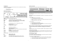
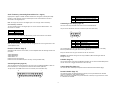
Setup Guide Addendum New features and amendments for DS2 models with built-in CDR Introduction Built-in CD writer This addendum sheet applies to DS2 units with a built-in CDR. The DS2 CD has the following features over the standard DS2: The Digital Sprite 2 CD has a built-in CDR accessible from the front panel. 1. 2. Built-in CD Writer. Onboard mains power supply. Quick Install (Page 5) The rear panel has now changed to: SERIAL 1 The operation of the internal CDR is identical to using the external CDR as described on the Quick Setup Card. S ERIA L 2 A UX R ELAYS AUX ALARMS POWER R1 R2 DIRECT VID 10 VID 11 VID 12 VID 13 VID 14 VID 15 VID 16 VID 3 VID 4 V ID 5 VID 6 VID 7 VID 8 VID 9 Note: Although the CDR has a DVD-ROM label on the drawer it is not possible to read or write to DVD media. A OUT IN B 485 B US + - + - BUS A BUS B G ND NE T SCSI L INE MIC MO N A MON VID 1 VID 2 To insert a CDR: 1. Press the button on the CDR drawer 2. Pull the CD drawer out until there is resistance 3. Place the CDR with the writing side up on the spindle and press down until there is a click. 4. Push the drawer back in until it latches. Connections at the rear of the DIGITAL SPRITE 2 CD Video VID1 to VID16 - 75Ω BNC composite camera connections (1V pk-pk). MON A - Main monitor, 75Ω BNC composite monitor connection (1V pk-pk). MON B - Spot monitor, 75Ω BNC composite monitor connection (1V pk-pk). SVHS - Main monitor, S-video monitor connection. Audio MIC LINE IN LINE OUT Data SCSI NET BUS A BUS B 485 BUS SERIAL 1 SERIAL 2 To remove a CDR: 1. Press the button on the CDR drawer 2. Pull the CD drawer out until there is resistance 3. Hold the CDR between thumb and forefinger and lift to remove from the spindle. 4. Push the drawer back in until it latches. - 3.5mm mono jack connection, -50dBV sensitivity or better (unbalanced Electret). - RCA (phono) socket, 47KΩ 1V pk-pk. - RCA (phono) socket, 1V pk-pk Note: In the event of a CD becoming jammed in the drive, or a power failure, it is possible to open the CDR drawer by inserting a thin object such as a paper clip, or watchmaker’s screwdriver into the small hole in the CDR drawer and applying pressure until the drawer unlocks. - 50-pin HD SCSI-2 connection. - RJ-45 10-baseT Ethernet connection. - RS-485 telemetry port 1. - RS-485 telemetry port 2 (Used in conjunction with BUS A with Sensormatic telemetry). - 2x MMJ ports for DM 485-BUS accessories. - 9-way (Male) D-type RS-232 serial port. - 9-way (Male) D-type RS-232 serial port. WARNING: The CDR is a Class 1 laser product to EN 60825-1:1994, avoid exposure to the beam. Selecting CD-Rs and CD-RWs The internal CD writer in the Digital Sprite 2 is not compatible with Ultra Speed CDR’s. Ensure that only High Speed or Multi-Speed CDR media is used. This is normally written on the CDR packaging and on the disk itself. Alarms and relays R1 - Relay dry contact, NO/NC. R2 - Relay dry contact, NO/NC. DIRECT - Direct auxiliary input, NO. ALARMS IN - 25-way (Female) D-type programmable direct alarms, NO/NC. RELAYS - 9-way (Female) D-type individual activity detection relays, NO. On-board power supply Previous models of Digital Sprite and Digital Sprite 2 units used an external PSU. The Digital Sprite 2 CD has an on-board mains power supply. To apply power to the Digital Sprite 2 CD : 1. Ensure all cameras, monitors and other connections are made, before continuing. 2. Insert the supplied IEC power lead into the Power socket at the rear of the unit. 3. Plug the unit into the power socket on the wall and switch on. 1 Serial Telemetry (Connecting External Devices – Page 6) PIN 1 – 16 17 21 – 25 Digital Sprite 2 supports a number of dome manufacturers using serial (twisted pair RS-485) telemetry. Serial telemetry requires a twisted pair connect from the dome to the Bus A connection on the Digital Sprite 2. Note: The D-type connectors on the Digital Sprite 2 are no longer used for telemetry. Connecting to the Relays (page 10) Serial telemetry connection The serial telemetry port on the Digital Sprite 2 is a screw terminal labelled ‘Bus A’. The connection is as follows: Bus A + - ALARM NUMBER 1 – 16 Global alarm input (default) or Schedule Ground There are extra relays available at the rear of the unit labelled RELAYS. The pin-out for the RELAYS connector is as follows (view from solder side). RS-485 Data A (TX+) Data B (TX-) 5 1 Bus B is also used if Sensormatic RS-422 telemetry is used. The connection is as follows: Bus A + - RS-422 TX+ TX- Bus B + - 9 RS-422 RX+ RX- Relay R3 R4 R5 R6 Note: The serial telemetry connection must be configured for the correct type of dome in the ‘System Options’ menu. External CD Writer (Page 7) 6 PIN 1&6 2&7 3&8 4&9 RELAY FUNCTION Camera Fail Hard Disk Fail Network Relay Not currently used The corresponding relay will close when there is a Camera fail, Hard disk fail, or the Relay button is pressed whilst using DM Network Viewing Software. Although the DS2 CD has an internal CDR, it is also compatible with the following external SCSI CD writers: Relays R1 and R2 are on the green connector at the rear of the unit. Yamaha CRW2200 SX Yamaha CRW3200 SX Yamaha CRW-F1 SX Plextor Plexwriter PX-W1210TSE Plextor Plexwriter PX-W4012TSE (This is the only currently available CDR) WARNING: The maximum rating of all the relays is 500mA @ 48V. Exceeding this load will damage the relays. Schedule (Page 16) Connecting alarms (page 10) The Set/Unset option in the Night and Weekend schedule can now use the AUX ALARM inputs on the rear of the unit to trigger the schedule to start and stop. There are now auxiliary alarm contacts on the rear of the unit labelled ALARMS IN. These can be used instead of, or in conjunction with external alarm modules (DM/CI01). Camera Recording (Page 16) This menu has been removed (now replaced with the Advanced Record Schedule page). The pin-out for the ALARMS IN connector are as follows (view from solder side). 13 25 1 Record Schedule (Page 17) The maximum record rate (Standard PPS or Event PPS) is now up to 50PPS for PAL standard cameras, and 60PPS for NTSC standard cameras. Note: A record rate of 50/60PPS is only achievable with 2 cameras, a single camera can record at a maximum of 25/30PPS. 14 2 Note: The Night and Weekend options are only displayed if a corresponding Night and Weekend schedule has been configured in the Schedule menu. Video Storage (Protected%) The total video storage in Gigabytes (GB) is displayed along with the percentage of video storage which is protected (will not be overwritten). Note that the calculations for recording time assume there is no protected video. Video that is protected will need to be manually unprotected in the ‘Record Options’ before it can be used for recording again. To change the priority of cameras to be recorded: Advanced Record Schedule (New page 19) Cameras connected to the Digital Sprite 2 can be recorded at a High, Medium (Standard) or Low priority for day, night, and weekend schedules. This allows cameras in sensitive areas to be recorded more frequently than cameras located in less sensitive areas. 1. 2. Ensure that the correct record rates have been set in the ‘Record Schedule’ menu. Move the cursor to a camera to be prioritised. 3. Tap either × or 4. 5. Ø to change the priority to Low , Standard , or High priority. It is also possible to disable recording of individual cameras by selecting . Continue to select the priority of each camera, notice that the update rates are automatically calculated depending on the number of cameras recording at each rate. If the update rate is not fast enough, you may need to reduce the nmber of high priority cameras or increase the record rate in the Record Schedule menu (although this will affect the recording time). Alarm Setup (Page 19) The Global alarm contact can now use any of the ALARMS IN inputs from the rear of the unit: Global alarm contact Aux Off Direct Module XX Contact XX Contact XX Multiple Alarms on a single camera If you are connecting multiple alarms to a single camera, please contact TSG for advice. Relay The relays can now be selected to open, close, momentary open, and momentary close on an alarm, activity, or cameras fail condition. A momentary close or open settings has a duration of half a second regardless of the alarm length. By default, all connected cameras are set at the Standard record priority; cameras that are not connected are greyed out and cannot be changed. As the user changes the priority levels, the update rate per camera (in seconds) is automatically calculated by the Digital Sprite 2 for High, Standard, and Low priority cameras and also the Average update rate. The update rate is based on the record rate (PPS) set in the Record Schedule menu and the number of cameras connected to the Digital Sprite 2. The update rate per camera is the number of seconds before the camera is updated when recorded, in the example above, during the day a High priority camera records every 1.54 seconds. Activity Setup (Page 20) Relay The relays can be configured for activity detection as above. The recording priority can be adjusted for each camera for Day, Night, and Weekend schedules. Note that changing the priority of a camera, or not recording cameras will not increase or decrease the recording time, the Record rate and the File size in the Record Schedule menu are used to set this. Display Setup (Page 21) There are new options for controlling a sequence on the Main monitor (Mon A): 3 Quad sequence DS2A supports a PPP (Point to Point Protocol) connection from the RS-232 serial port 1 or 2. This port allows a US Robotics modem to be connected directly to the D4 for dial-up. Page, Segment PPP address By default the PPP IP address is 172.17.2.2, this can be changed by selecting a different Network IP address. The PPP address cannot be changed directly, but is changed automatically when the TCP/IP address is adjusted. The unit can be on a network and be dialled into at the same time because the PPP address is not on the same subnet as the network. For example, if the network IP address is 172.16.1.20 and the subnet mask is 255.255.0.0 the PPP address will be 172.17.1.20 – not on the same subnet. The sequence on a quad display can either be a page at a time, i.e. cameras 1, 2, 3, and 4, then 5, 6, 7, 8 etc. or a segment sequence, i.e. the bottom right hand segment in the quad sequences. Sequence dwell 5 sec, 1 – 99 sec. The dwell time can be set from between 1 and 99 seconds. The dwell time is the length of time a camera in the sequence is displayed before switching to the next camera. Serial telemetry type None, [dome manufacturer] The following domes have been added to the menu: Tip: The cameras in the sequence can be edited by pressing and holding the Sequence button when in Live mode. Mark Mercer, Samsung, Vista PowerDome. System Options (Page 22) Record Options (new page 24) Under Network settings A new menu page has been added which is used for setting up how the disk is used to record images. MTU The ability to set the MTU (Maximum Transfer Unit) has been added to the Network Settings page: MTU 576 - 1500 The MTU is the largest physical packet size, measured in bytes, which a network can transmit. Any messages larger than the MTU are divided into smaller packets before being sent. Ideally, the MTU should be the same as the smallest MTU of all the networks between your machine and the final destination. If the MTU figure is too large packets will be broken up (fragmented), which slows down transmission speeds, and in some cases cause a ‘Connection to Unit Timed Out’ message when using DM Network Viewing Software. MTU sizes can vary for each connection and it may be necessary to use trial and error to find the optimal MTU, if you are unsure about the MTU size, use the default setting (576) and work up if necessary. Typical MTU sizes are as follows: Network Connection PPP (ISDN/PSTN routers) Ethernet PPPoE (PPP over Ethernet, ADSL, Cable) PPPoA (PPP over ATM, ADSL, Cable) VPN MTU size 576 (default) 1500 1458 1458 1350 Event partition (see page 23 in the Setup Guide) Warning: Changing the MTU size can have an adverse affect on the transmission speed and operation over the network. Check with your network administrator or service provider for advice on the correct MTU size for the network. Event copy destination The event copy destination is the external device where the images will be sent when events are copied. PPP port PPP Port Timed expiry (see page 24 in the Setup Guide) Serial 1, Serial 2 Event copy destination (see page 23 in the Setup Guide) 4 may be necessary to wait a few minutes for the remaining images to be protected before unprotecting them. Alarm protection Global and Panic alarms can be protected automatically as they are received. Select whether Global, Panic, or Global and Panic alarms are protected. If no alarms are to be protected, select Disabled. Important information regarding Protected Images. There is a percentage indication of the amount of images that are currently protected on the hard disk. It is important to remember that the protected images will remain on the hard disk and will not be overwritten until they are manually removed. Protected images reduce the amount of space you have for normal recording. For example, if 50% of the images are protected, this effectively means you only have half the disk available for normal recording, so recording settings that should normally give you 30 days would only allow 15 days of recording. Pre-alarm protection This is the amount of time the images are protected before the Global or Panic alarm is triggered. By default this setting is 15 minutes, but this is adjustable from 00 minutes (no prealarm protection) to 60 minutes. Post-alarm protection This is the amount of time the images are protected after the Global or Panic alarm has ended. By default this setting is 15 minutes, but this is adjustable from 00 minutes (no post-alarm protection) to 60 minutes. System Options (page 22) Some items in the System Options page have been moved to different menus. The new menu pages are: Option Event Partition Event copy destination Image Storage Timed Expiry Protected images Selecting this option allows images to be protected or unprotect manually. New Menu Page Record options Record options Record options Record options Serial Telemetry The Samsung SCC-641 dome protocol has been added to the list of serial telemetry types. The dome menu controls using the DM keyboard are: Press 7 to enter the menus. Use the joystick to navigate the menus, and press Enter to select an option. Press and hold 7 to exit the menus. To protect images: 1. Enter the time of the first image to be protected (in the From area). 2. Enter the time of the last image to be protected (in the To area). 3. Select ‘Confirm’ in the Protect images option. 4. The selected images are protected and placed in the list. To unprotect images: 1. Enter the time of the first image to be protected (in the From area), or highlight an image in the list and press Camera 1. 2. Enter the time of the last image to be protected (in the To area), or highlight an image in the list and press Camera 2. 3. Select ‘Confirm’ in the Unprotect images option. 4. The selected images are unprotected and removed from the list. Note: If you try to unprotect a sequence of images before they are all protected, if you are protecting a large number of images for example, some of the images may be left in the list. It 5 Activity to Enter the time and date you wish to search to. New Operations Playback time Select this option to automatically enter the last playback time and date the user was viewing into the ‘Activity to’ option. Activity search It is possible to search an area of the screen for activity or text at specified times. To search for activity or text: 1. 2. 3. Once the Search Setup screen has been completed, press following screen is displayed. to begin the search, the Enter playback mode by tapping either ,, or pressing and holding the GOTO key. Press and hold the ‘Event’ key to display the Search Setup menu: The Digital Sprite 2 will search the hard disk for activity in the selected areas. Once it has found 20 (for PAL units) or 18 (for NTSC cameras) events the activity list will appear. The search can be cancelled at any time by tapping the ‘Event’ key; any events found up to that point will displayed in the activity list. A typical example of an Activity List would be: Camera This is the camera number you will be performing the search on, press a camera key to change to the relevant camera number. Define This option defines the area of the screen you need to search. Follow the on-screen instructions to select an area of the screen to search for activity. Copy destination This is the device you wish to copy selected images to, (select External to copy to Zip/Jaz, or CDR List to copy to the CDR Archive page). Use the Ç È keys to move the highlight up and down the list, the Activity image is automatically updated as the highlight moves. From this screen you can perform the following: Activity from Enter the time and date you wish to search from. The default is the earliest recorded time on the disk. Play an activity back in full screen Highlight the required activity event and pressto play it back in full screen. Tap the ‘Event’ key to return to the Activity list. 6 Copy an event to CDR or external Zip and Jaz Highlight the event to be copied, and press the copy button. The event will be copied to the CDR Archive list. If the ‘Copy destination on the previous page is set to ‘External’, then the images will be copied to an external Zip or Jaz disk. Using the remote control View more activities To view more than a page of activities scroll down to the bottom of the list, the unit will search further back in time and another list of activities will appear. When there are no more activities to list an end bar ‘===============’ is displayed. To use the remote control the ‘IR receiver’ option needs to be enabled in the ‘System Options’ menu page. The remote control provides the following functions: The remote control included with the Digital Sprite 2 operates the same as the front panel, see the operator card for details. UNIT SELECT MODE Start a new search If you wish to start a new search, you must tap the ‘menu’ key to exit the Activity list, then reenter ‘Search Setup’ as described in step 1. HOLD SPOT Recording to the internal CDR Recording to the internal CDR has exactly the same operation as you would if you are recording to external CDR devices. The recording to CDR section on the ‘Using DS2’ card also applies to the internal drive. EVENT GOTO 1 –16 Õ×ØÖ The ‘Copy Destination’ is the one difference that is apparent in the menus, to copy to the internal CDR, select ‘CDO: IDE 0 TOSHIBA DVD-ROM’. Press ‘UNIT SELECT’ followed by a camera key to log onto another unit. Press to toggle Spot mode on and off, or to return to Live mode when playing back. Toggle freeze frame On and Off. Toggle Spot mode on and off, Selects operation of the spot monitor. Press to display the Event log. Press to display the Goto time option. Camera selection keys. Use to control the cursor in menus, or scroll around the screen when in zoom mode. Control playback of the Digital Sprite 2. Notes: The remote control does not have the ability to control a video switcher if multiple units are connected together, only a remote keyboard has this ability. If multiple Digital Sprite 2s are connected together using the 485bus, only one of these units should have the IR receiver enabled. The option to disable the IR receiver is in the System Options menu page. 7 Rack mounting kit A rack mounting kit is supplied with this product, it is important to use it correctly. The kit comprises of: 4x (Rack mount screws) 2x (Rack mount ears) 2x (Rear supports) Installation Before connecting cables to the back of the unit: 1. 2. 3. 4. Attach the rear supports to the rack. Using the supplied screws, attach the rack mount ears to each side of the unit. Position the unit on the rear supports. Attach the rack mount ears to the front of the rack. Warning: The rear supports must be used when rack mounting the product, failure to use them may cause damage to the unit. 8 9 MI-A-DS2AC/E1-1 Dedicated Micros, March 2004