1
CS100 Barometric
Pressure Sensor
Revision: 8/12
C o p y r i g h t © 2 0 0 2 - 2 0 1 2
C a m p b e l l S c i e n t i f i c , I n c .
Warranty
“PRODUCTS MANUFACTURED BY CAMPBELL SCIENTIFIC, INC. are
warranted by Campbell Scientific, Inc. (“Campbell”) to be free from defects in
materials and workmanship under normal use and service for twelve (12)
months from date of shipment unless otherwise specified in the corresponding
Campbell pricelist or product manual. Products not manufactured, but that are
re-sold by Campbell, are warranted only to the limits extended by the original
manufacturer. Batteries, fine-wire thermocouples, desiccant, and other
consumables have no warranty. Campbell's obligation under this warranty is
limited to repairing or replacing (at Campbell's option) defective products,
which shall be the sole and exclusive remedy under this warranty. The
customer shall assume all costs of removing, reinstalling, and shipping
defective products to Campbell. Campbell will return such products by surface
carrier prepaid within the continental United States of America. To all other
locations, Campbell will return such products best way CIP (Port of Entry)
INCOTERM® 2010, prepaid. This warranty shall not apply to any products
which have been subjected to modification, misuse, neglect, improper service,
accidents of nature, or shipping damage. This warranty is in lieu of all other
warranties, expressed or implied. The warranty for installation services
performed by Campbell such as programming to customer specifications,
electrical connections to products manufactured by Campbell, and product
specific training, is part of Campbell’s product warranty. CAMPBELL
EXPRESSLY DISCLAIMS AND EXCLUDES ANY IMPLIED
WARRANTIES OF MERCHANTABILITY OR FITNESS FOR A
PARTICULAR PURPOSE. Campbell is not liable for any special, indirect,
incidental, and/or consequential damages.”
Assistance
Products may not be returned without prior authorization. The following
contact information is for US and international customers residing in countries
served by Campbell Scientific, Inc. directly. Affiliate companies handle
repairs for customers within their territories. Please visit
www.campbellsci.com to determine which Campbell Scientific company serves
your country.
To obtain a Returned Materials Authorization (RMA), contact CAMPBELL
SCIENTIFIC, INC., phone (435) 227-9000. After an applications engineer
determines the nature of the problem, an RMA number will be issued. Please
write this number clearly on the outside of the shipping container. Campbell
Scientific's shipping address is:
CAMPBELL SCIENTIFIC, INC.
RMA#_____
815 West 1800 North
Logan, Utah 84321-1784
For all returns, the customer must fill out a "Statement of Product Cleanliness
and Decontamination" form and comply with the requirements specified in it.
The form is available from our web site at www.campbellsci.com/repair. A
completed form must be either emailed to repair@campbellsci.com or faxed to
(435) 227-9106. Campbell Scientific is unable to process any returns until we
receive this form. If the form is not received within three days of product
receipt or is incomplete, the product will be returned to the customer at the
customer's expense. Campbell Scientific reserves the right to refuse service on
products that were exposed to contaminants that may cause health or safety
concerns for our employees.
Table of Contents
PDF viewers: These page numbers refer to the printed version of this document. Use the
PDF reader bookmarks tab for links to specific sections.
1. Introduction .................................................................1
2. Cautionary Statements...............................................1
3. Initial Inspection .........................................................1
4. Quickstart ....................................................................1
4.1
4.2
Step 1 — Mount Sensor to an Enclosure Backplate.............................1
Step 2 — Use SCWin Short Cut to Program Datalogger and
Generate Wiring Diagram.................................................................2
5. Overview......................................................................4
6. Specifications .............................................................6
6.1
Performance .........................................................................................6
6.1.1 Performance for “Standard” Range Option...................................6
6.1.2 Performance for “500 to 1100 mb” Range Option........................7
6.1.3 Performance for “800 to 1100 mb” Range Option........................7
6.2
Electrical ..............................................................................................7
6.3
Physical ................................................................................................7
7. Installation ...................................................................8
7.1
7.2
Enclosure Considerations.....................................................................8
Wiring ..................................................................................................9
7.2.1 Datalogger Connection .................................................................9
7.2.2 5-pin Screw Terminal Plug Connector........................................10
7.3
Programming......................................................................................11
7.3.1 Conversion Factors .....................................................................11
7.3.2 Multipliers and Offsets for Different Measurement Range
Options ....................................................................................11
7.3.3 Program Examples ......................................................................12
7.3.3.1 CRBasic Example 1: CR1000 Program Using
Sequential Mode ...........................................................12
7.3.3.2 CRBasic Example 2: CR1000 Program Using
Pipeline Mode...............................................................13
7.3.3.3 Edlog Example — CR10X Program ................................14
7.3.4 Output Resolution .......................................................................15
7.4
Correcting Pressure to Sea Level .......................................................15
8. Maintenance and Calibration ...................................16
i
Table of Contents
Figures
5-1.
7-1.
7-2.
7-3.
CS100 Barometric Pressure Sensor..................................................... 5
ENC100 is a very small enclosure that can house one CS100 ............ 8
CS100 as removed from the box ......................................................... 9
Connector key attached to 5-pin screw terminal plug connector....... 10
7-1.
7-2.
7-3.
7-4.
Signal and Ground Connectors for CS100 ........................................ 10
Conversion Factors for Alternative Pressure Units ........................... 11
Multipliers and Offsets ...................................................................... 11
Wiring for Example Programs........................................................... 12
Tables
ii
CS100 Barometric Pressure Sensor
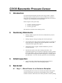
1.
Introduction
The CS100 measures barometric pressure for the range of 600 to 1100 mb.
This range equates to from below sea level (as in a mine) up to 12,000 feet
above sea level. Designed for use in environmental applications, the CS100 is
compatible with all Campbell Scientific dataloggers.
Before using the CS100, please study
•
•
•
Section 2, Cautionary Statements
Section 3, Initial Inspection
Section 4, Quickstart
More details are available in the remaining sections.
2.
3.
Cautionary Statements
•
Warning: Failure to protect the sensor from condensation may result in
permanent damage.
•
Warning: Improper wiring may damage the CS100 beyond repair.
•
Care should be taken when opening the shipping package to not damage or
cut the cable jacket. If damage to the cable is suspected, consult with a
Campbell Scientific applications engineer.
•
Although the CS100 is rugged, it should be handled as a precision
scientific instrument.
•
The black outer jacket of the cable is Santoprene® rubber. This
compound was chosen for its resistance to temperature extremes, moisture,
and UV degradation. However, this jacket will support combustion in air.
It is rated as slow burning when tested according to U.L. 94 H.B. and will
pass FMVSS302. Local fire codes may preclude its use inside buildings.
Initial Inspection
•
4.
Upon receipt of the CS100, inspect the packaging and contents for
damage. File damage claims with the shipping company.
Quickstart
4.1
Step 1 — Mount Sensor to an Enclosure Backplate
The mounting holes for the sensor are one-inch-centered (three inches apart),
and will mount directly onto the holes on the backplates of the Campbell
Scientific enclosures. Mount the sensor with the pneumatic connector pointing
1
CS100 Barometric Pressure Sensor
vertically downwards to prevent condensation collecting in the pressure cavity,
and also to ensure that water cannot enter the sensor.
4.2
Step 2 — Use SCWin Short Cut to Program Datalogger
and Generate Wiring Diagram
The simplest method for programming the datalogger to measure the CS100 is
to use Campbell Scientific's SCWin Short Cut Program Generator.
2
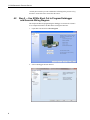
1.
Open Short Cut and click on New Program.
2.
Select a datalogger and scan interval.
CS100 Barometric Pressure Sensor
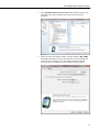
3.
Select CS100 Barometric Pressure Sensor then click the right arrow in
the middle of the page to add the sensor to the list of sensors to be
measured.
4.
Define the name of the public variables. Variable defaults to BP_mmHg
that holds the barometric pressure measurements. Select the desired units
of measure, pressure range, sea level elevation correction, elevation
correction units, and whether the sensor should be measured hourly.
3
CS100 Barometric Pressure Sensor
WARNING
5.
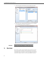
5.
Choose the outputs for the barometric pressure and then select finish.
6.
Remove the yellow warning label from the pigtails and wire according to
the wiring diagram generated by SCWin Short Cut.
Improper wiring may damage the CS100 beyond repair.
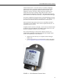
Overview
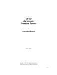
The CS100 is a capacitive pressure transducer that uses the Setra's electrical
capacitor technology for barometric pressure measurements over the 600 to
1100 millibar range. The transducer’s compact and rugged polyester housing
with stainless blackplate contains two closely-spaced, parallel, electrically-
4
CS100 Barometric Pressure Sensor
isolated metallic surfaces. One of the surfaces is essentially a diaphragm
constructed of a Setra’s proprietary compound of fused glass and ceramic
(Setraceram™) or a low-hysteresis material, such as 17-4 PH SS. The
diaphragm is capable of detecting a slight change in the applied pressure,
which is then converted to an analog voltage signal by Setra’s custom
Application Specific Integrated Circuit (ASIC). The analog signal generated
by the barometer can be directly measured by a Campbell Scientific datalogger.
The CS100 is supplied in the triggered mode, in which the datalogger switches
12 VDC power to the barometer before the measurement. The datalogger then
powers down the barometer after the measurements to conserve power.
Other measurement range options such as 500 to 1100 millibar, and 800 to
1100 millibar are also available. Please contact Campbell Scientific, Inc. for
ordering these special versions.
Campbell Scientific offers the CS100-QD, a version of the CS100 that includes
a connector for use with a RAWS-F or RAWS-P weather station (refer to the
RAWS-F and RAWS-P manuals for more information).
If the CS100 and datalogger will be housed in different enclosures, the
CABLE5CBL-L should be used instead of the cable that is shipped with the
CS100. The CABLE5CBL-L can terminate in:
•
•
Pigtails that connect directly to a Campbell Scientific datalogger
(option –PT).
Connector that attaches to a prewired enclosure (option –PW). Refer
to www.campbellsci.com/prewired-enclosures for more information.
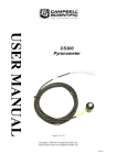
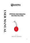
FIGURE 5-1. CS100 Barometric Pressure Sensor
5
CS100 Barometric Pressure Sensor
6.
Specifications
Features:
•
Integral switching circuit limits power consumption to measurement
cycle
•
Compatible with all Campbell Scientific dataloggers (including the
CR200(X) series)
•
Calibration NIST traceable
•
Meets CE conformance standards
Compatibility
Dataloggers:
6.1
CR200(X) series
CR800 series
CR1000
CR3000
CR5000
CR9000(X)
CR7X
CR510
CR10(X)
CR23X
21X
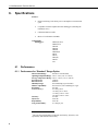
Performance
6.1.1 Performance for “Standard” Range Option
Measurement Range:
600 mb to 1100 mb (hPa)
Operating Temperature Range: -40° to +60°C (-40° to +140°F)
Storage Temperature Range: -60° to +120°C (-76° to +248°F)
Proof Pressure:
1500 mb
Burst Pressure:
2000 mb
Humidity Range:
non-condensing (up to 95% RH)
Media Compatibility:
non-corrosive, non-condensing air or gas
Resolution:
0.01 mb
±0.5 mb @ 20°C
Total Accuracy 1 :
±1.0 mb @ 0° to +40°C
±1.5 mb @ -20° to +50°C
±2.0 mb @ -40° to +60°C
Linearity:
±0.4 mb
Hysteresis:
±0.05 mb
Repeatability:
±0.03 mb
Long-term Stability:
±0.1 mb per year
1
The root sum squared (RSS) of end point non-linearity, hysteresis, nonrepeatability and calibration uncertainty.
6
CS100 Barometric Pressure Sensor
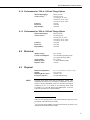
6.1.2 Performance for “500 to 1100 mb” Range Option
Measurement Range:
Total Accuracy 2 :
Linearity:
Hysteresis:
Repeatability:
500 to 1100 mb
±0.6 mb @ 20°C
±1.2 mb @ 0° to +40°C
±2.0 mb @ -20° to +50°C
±2.5 mb @ -40° to +60°C
±0.5 mb
±0.06 mb
±0.04 mb
6.1.3 Performance for “800 to 1100 mb” Range Option
Measurement Range:
Total Accuracy 3 :
Linearity:
Hysteresis:
Repeatability:
6.2
Electrical
Supply Voltage:
Current Consumption:
6.3
800 to 1100 mb
±0.3 mb @ 20°C
±0.6 mb @ 0° to +40°C
±1.0 mb @ -20° to +50°C
±1.5 mb @ -40° to +60°C
±0.25 mb
±0.03 mb
±0.02 mb
Signal Output:
Warm-up Time:
Response Time:
9.5 to 28 Vdc
3 mA nominal (operating mode)
1 µA quiescent (sleep mode)
0 to 2.5 Vdc
<1 s from shutdown mode
<100 ms
Dimensions (Main Box):
Weight:
Mounting Hole Centers:
Pressure Connector:
9.1 x 6.1 x 2.5 cm (3.6 x 2.4 x 1.0 in)
135 g (4.8 oz)
7.62 cm (3 in)
1/8 in ID barbed fitting
Physical
NOTE
The black outer jacket of the cable is Santoprene® rubber. This
compound was chosen for its resistance to temperature extremes,
moisture, and UV degradation. However, this jacket will support
combustion in air. It is rated as slow burning when tested
according to U.L. 94 H.B. and will pass FMVSS302. Local fire
codes may preclude its use inside building.
2
The root sum squared (RSS) of end point non-linearity, hysteresis, nonrepeatability and calibration uncertainty.
3
The root sum squared (RSS) of end point non-linearity, hysteresis, nonrepeatability and calibration uncertainty.
7
CS100 Barometric Pressure Sensor
7.
Installation
7.1
Enclosure Considerations
To prevent condensation, install the sensor in an environmentally protected
enclosure, complete with desiccant, which should be changed at regular
intervals.
CAUTION
Failure to protect the sensor from condensation may result
in permanent damage.
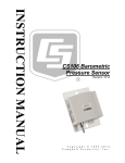
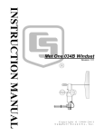
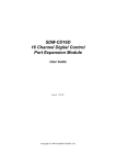
The CS100 is typically mounted in a Campbell Scientific enclosure next to the
datalogger. Campbell Scientific also offers the ENC100 for situations where it
is desirable to house the CS100 in its own enclosure. The ENC100 is a 6.7-in.
x 5.5-in. x 3.7-in. enclosure that includes a compression fitting for cable entry,
a vent for equalization with the atmosphere, a backplate for mounting the
CS100, and hardware for mounting the ENC100 to a tripod, tower, or pole (see
FIGURE 7-1).
FIGURE 7-1. ENC100 is a very small enclosure that can house one
CS100
8
CS100 Barometric Pressure Sensor
Remember that for the sensor to detect the external ambient pressure, the
enclosure must vent to the atmosphere (i.e., not be hermetically sealed).
Enclosures purchased from Campbell Scientific properly vent to the
atmosphere.
NOTE
7.2
For user-supplied enclosures, it may be necessary to make a vent
hole on the outer wall. In this situation, do not make the hole on
one of the vertical side walls, as wind blowing around it can
cause transient changes in pressure.
Wiring
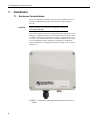
7.2.1 Datalogger Connection
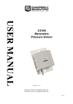
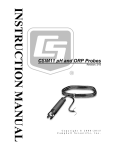
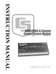
Before connecting the barometer to the datalogger, a yellow warning label
must be removed from the pigtails (see FIGURE 7-2). The warning label
reminds the user of the importance of properly connecting the barometer to the
datalogger. Proper wiring is shown in TABLE 7-1.
Yellow Warning Label
FIGURE 7-2. CS100 as removed from the box
9
CS100 Barometric Pressure Sensor
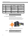
TABLE 7-1. Signal and Ground Connectors for CS100
Wire
CS100 Terminal
Datalogger
Single-Ended Measurement
Datalogger
Differential Measurement
Blue
VOUT
S.E. Input
High Side of Diff Input
Yellow
AGND
AG (CR10(X), CR500, CR510)
(Other Dataloggers)
Low Side of Diff. Input
Black
GND
(21X, CR7, CR9000(X))
G (Other Dataloggers)
(21X, CR7, CR9000(X))
G (Other Dataloggers)
Green
EXT TRIG
Control port (use to turn power
on/off)
Control port (use to turn power
on/off)
Red
SUPPLY
12 VDC
12 VDC
Shield
Shield
G (CR10(X), CR500, CR510)
(Other Dataloggers)
G (CR10(X), CR500, CR510)
(Other Dataloggers)
WARNING
Improper wiring may damage the CS100 beyond repair.
7.2.2 5-pin Screw Terminal Plug Connector
The datalogger connects to the CS100 via a 5-pin screw terminal plug
connector. This connector is removable and may be replaced. The
replacement connector may come with a connector key attached to it to ensure
that the connector is plugged into the CS100 right side up (see FIGURE 7-3).
When the connector is right side up, it will easily plug into the barometer.
FIGURE 7-3. Connector key attached to 5-pin screw terminal plug
connector
WARNING
10
A 5-pin screw terminal that is plugged in upside down
will damage the sensor—perhaps beyond repair.
CS100 Barometric Pressure Sensor
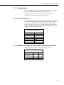
7.3
Programming
The CS100 sensor is measured using the singled-ended voltage measurement
instruction (VoltSE() in CRBasic and Instruction 1 in Edlog).
Atmospheric pressure changes little with time. In most weather station
applications measuring pressure once an hour is adequate.
7.3.1 Conversion Factors
In the example programs, the pressure is reported in millibars (mb). To report
pressure in different units, multiply the measured pressure by the appropriate
conversion factor using the P37 (Z=X*F) instruction for CR500, CR510,
CR10(X), CR23X, 21X, and CR7, or by adding an expression for CR200(X),
CR800, CR850, CR1000, CR3000, CR5000, and CR9000(X) dataloggers. See
TABLE 7-2 below for conversion factors.
TABLE 7-2. Conversion Factors for
Alternative Pressure Units
To Find
hPa
kPa
mm of Hg
in of Hg
Psi
Atm
Torr
Multiply by
1.0
0.1
0.75006
0.02953
0.0145
0.00099
0.75006
7.3.2 Multipliers and Offsets for Different Measurement Range Options
Please refer to the table below for proper multipliers and offsets.
TABLE 7-3. Multipliers and Offsets
Range Options
600 to 1100 mb
(Standard range)
500 to 1100 mb
800 to 1100 mb
Multiplier
0.2
Offset
600
0.24
0.12
500
800
11
CS100 Barometric Pressure Sensor
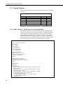
7.3.3 Program Examples
The CS100 wiring instructions for the example programs are shown in TABLE
7-4 below.
TABLE 7-4. Wiring for Example Programs
Wire Color
Blue
Red
Black
Yellow
Green
Clear
Description
VOUT – Pressure Signal Out
SUPPLY – 12 Vdc Power In
GND – Power Ground
AGND – Signal Ground
ETX. TRIG. – External Trigger
Shield
CR10(X)
SE6
12V
G
AG
C8
G
CR1000
SE15
12V
G
C4
G
7.3.3.1 CRBasic Example 1: CR1000 Program Using Sequential Mode
This CR1000 program uses the sequential mode, which is the simplest mode
and can be used for most meteorological applications. Although the example is
for the CR1000, other CRBasic dataloggers, such as the CR200(X), CR800,
CR850, CR3000, and CR9000(X) are programmed similarly. In the example,
the CR1000 measures the CS100 once an hour. To do this, the CR1000 uses a
control port to turn on the CS100 one minute before the top of the hour. On the
hour, the datalogger measures the CS100, and then turns the CS100 off.
'CR1000
'Declare Variables and Units
Public BattV
Public PTemp_C
Public BP_mmHg
Units BattV=Volts
Units PTemp_C=Deg C
Units BP_mmHg=mmHg
'Define Data Tables
DataTable(Table1,True,-1)
DataInterval(0,60,Min,10)
Sample(1,BP_mmHg,FP2)
EndTable
DataTable(Table2,True,-1)
DataInterval(0,1440,Min,10)
Minimum(1,BattV,FP2,False,False)
EndTable
'Main Program
BeginProg
'Main Scan
Scan(5,Sec,1,0)
'Default Datalogger Battery Voltage measurement 'BattV'
Battery(BattV)
'Default Wiring Panel Temperature measurement 'PTemp_C'
PanelTemp(PTemp_C,_60Hz)
'CS100 Barometric Pressure Sensor measurement 'BP_mmHg'
If IfTime(59,60,Min) Then PortSet(4,1)
If IfTime(0,60,Min) Then
VoltSE(BP_mmHg,1,mV2500,15,1,0,_60Hz,0.2,600)
BP_mmHg=BP_mmHg*0.75006
PortSet(4,0)
12
CS100 Barometric Pressure Sensor
EndIf
'Call Data Tables and Store Data
CallTable(Table1)
CallTable(Table2)
NextScan
EndProg
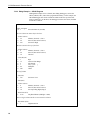
7.3.3.2 CRBasic Example 2: CR1000 Program Using Pipeline Mode
Although this example is for the CR1000, other CRBasic dataloggers, such as
the CR200(X), CR800, CR850, CR3000, and CR9000(X) are programmed
similarly. In the example, the CR1000 measures the CS100 once an hour in a
program that runs at 1 Hz. In order to keep the CR1000 running in a pipeline
mode, the measurement instruction is placed outside the “If” statement. The
measurement is made every scan, and the measured value is first written into a
temporary variable called "CS100_temp". Once the CS100 is turned on one
minute before the hour, the CS100 starts to make the correct pressure
measurements. At the top of the hour, the correct value is copied into the
current variable called "pressure", and the sensor is turned off immediately.
'CR1000 Datalogger
Public CS100_temp
Public pressure
Units pressure = mbar
DataTable (met_data,True,-1)
DataInterval (0,60,min,10)
Sample (1,pressure,IEEE4)
EndTable
BeginProg
Scan (1,sec,3,0)
'Measurement is made every scan outside the “If” statement
VoltSE (CS100_temp,1,mV2500,15,False,200,250,0.2,600)
'Turn on CS100 one minute before the hour
If (IfTime (59,60,min)) Then WriteIO (&b1000,&b1000)
'Copy the correct value to a current variable called “pressure” at the top of the
hour
'Turn off CS100 after measurement
If (IfTime (0,60,min)) Then
pressure = CS100_temp
WriteIO (&b1000,&b0)
EndIf
CallTable met_data
NextScan
EndProg
13
CS100 Barometric Pressure Sensor
7.3.3.3 Edlog Example — CR10X Program
Although this example is for a CR10X, other Edlog dataloggers, such as the
CR510, CR23X, CR7, and 21X are programmed similarly. In the example, the
CR10X datalogger turns on the CS100 one minute before the top of the hour
using a control port. On the hour, the datalogger measures the CS100, and then
it turns the CS100 off.
;{CR10X}
;
*Table 1 Program
01: 1
Execution Interval (seconds)
;Turn on CS100 one minute before the hour
;
1: If time is (P92)
1: 59
Minutes (Seconds --) into a
2: 60
Interval (same units as above)
3: 48*
Set Port 8* High
;Measure CS100 at the top of the hour
;
2: If time is (P92)
1: 0
Minutes (Seconds --) into a
2: 60
Interval (same units as above)
3: 30
Then Do
3: Volt (SE) (P1)
1: 1
2: 15
3: 6
4: 1
5: 0.2
6: 600
Reps
2500 mV Fast Range
SE Channel
Loc [ P_mb ]
Multiplier
Offset
;Turn off CS100
;
4: Do (P86)
1: 58*
Set Port 8* Low
5: End (P95)
6: If time is (P92)
1: 0
Minutes (Seconds --) into a
2: 60
Interval (same units as above)
3: 10
Set Output Flag High (Flag 0)
7: Real Time (P77)
1: 0110
Day,Hour/Minute (midnight = 0000)
;Store in high resolution mode to retain 0.01mb resolution
;
8: Resolution (P78)
1: 1
High Resolution
14
CS100 Barometric Pressure Sensor
9: Sample (P70)
1: 1
2: 1*
Reps
Loc [ P_mb
]
*Table 2 Program
02: 0.0000
Execution Interval (seconds)
*Table 3 Subroutines
End Program
-Input Locations1 P_mb
* Proper entries will vary with program and datalogger channel, and input location assignments.
7.3.4 Output Resolution
When storing the values from the CS100 to a data table or to a datalogger’s
final storage location, care must be taken to choose suitable scaling of the
reading, or to store the value with adequate resolution to avoid losing useful
resolution of the pressure measurement. The default resolution (low
resolution) for Campbell Scientific dataloggers is limited to a maximum of four
digits. Even then, the maximum digit value that can be displayed is 6999 for
Edlog dataloggers, and 7999 for the CRBasic dataloggers. If you use this
option with barometric data scaled in millibars (hPa), a reading above
799.9 mb for CRBasic dataloggers or 699.9 mb for Edlog dataloggers will lose
one digit of resolution, e.g. at 900 mb, the resolution is limited to 1 mb.
To retain 0.01 mb resolution, you either need to deduct a fixed offset from the
reading before it is stored to avoid exceeding the 799.9 for CRBasic
dataloggers or 699.9 for Edlog dataloggers threshold, or output the barometric
reading in high resolution format. This can be done by using the IEEE4 format
for the CR800, CR850, CR1000, CR3000, CR5000, and CR9000(X)
dataloggers or using the Resolution (P78) instruction for our Edlog
dataloggers. The default data output format for CR200(X) series datalogger is
IEEE4.
7.4
Correcting Pressure to Sea Level
The weather service, most airports, radio stations, and television stations adjust
the atmospheric pressure to a common reference (sea level). Equation 1 can be
used to find the difference in pressure between the sea level and the site. That
value (dP) is then added to the offset (600 mb in our example programs) in the
measurement instruction. U. S. Standard Atmosphere and dry air were
assumed when Equation 1 was derived (Wallace, J. M. and P. V. Hobbes,
1977: Atmospheric Science: An Introductory Survey, Academic Press,
pp. 59-61).
⎧⎪ ⎛
⎞5.25328 ⎫⎪
E
⎬
dP = 1013.25 ⎨1 − ⎜1 −
⎟
⎪⎭
⎪⎩ ⎝ 44307.69231⎠
(1)
15
CS100 Barometric Pressure Sensor
The value dP is in millibars and the site elevation, E, is in meters. Add dP
value to the offset in the measurement instruction.
Use Equation (2) to convert feet to meters.
E(m) =
E( ft )
3.281ft m
(2)
The corrections involved can be significant: e.g. at 1000mb and 20°C,
barometric pressure will decrease by 1.1mb for every 10 meter increase in
altitude.
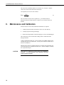
8.
Maintenance and Calibration
Since the sensor is semi-sealed, minimum maintenance is required:
1.
Visually inspect the cable connection to ensure it is clean and dry.
2.
Visually inspect the casing for damage.
3.
Ensure that the pneumatic connection and pipe are secure and undamaged.
The external case can be cleaned with a damp, lint-free cloth and a mild
detergent solution.
Contact Campbell Scientific, Inc. (435-227-9000) for an RMA number before
returning the sensor for recalibration. You may also return the unit directly to
Setra for recalibration.
Should you lose the five terminal connector (p/n 16004), the replacement part
can be purchased from Campbell Scientific, Inc. Contact Campbell Scientific,
Inc. to purchase the part.
CAUTION
16
The CS100 is sensitive to static when the backplate is
removed. To avoid damage, take adequate anti-static
measures when handling.
Campbell Scientific Companies
Campbell Scientific, Inc. (CSI)
815 West 1800 North
Logan, Utah 84321
UNITED STATES
www.campbellsci.com • info@campbellsci.com
Campbell Scientific Africa Pty. Ltd. (CSAf)
PO Box 2450
Somerset West 7129
SOUTH AFRICA
www.csafrica.co.za • cleroux@csafrica.co.za
Campbell Scientific Australia Pty. Ltd. (CSA)
PO Box 8108
Garbutt Post Shop QLD 4814
AUSTRALIA
www.campbellsci.com.au • info@campbellsci.com.au
Campbell Scientific do Brazil Ltda. (CSB)
Rua Luisa Crapsi Orsi, 15 Butantã
CEP: 005543-000 São Paulo SP BRAZIL
www.campbellsci.com.br • suporte@campbellsci.com.br
Campbell Scientific Canada Corp. (CSC)
11564 - 149th Street NW
Edmonton, Alberta T5M 1W7
CANADA
www.campbellsci.ca • dataloggers@campbellsci.ca
Campbell Scientific Centro Caribe S.A. (CSCC)
300 N Cementerio, Edificio Breller
Santo Domingo, Heredia 40305
COSTA RICA
www.campbellsci.cc • info@campbellsci.cc
Campbell Scientific Ltd. (CSL)
Campbell Park
80 Hathern Road
Shepshed, Loughborough LE12 9GX
UNITED KINGDOM
www.campbellsci.co.uk • sales@campbellsci.co.uk
Campbell Scientific Ltd. (France)
3 Avenue de la Division Leclerc
92160 ANTONY
FRANCE
www.campbellsci.fr • info@campbellsci.fr
Campbell Scientific Spain, S. L.
Avda. Pompeu Fabra 7-9, local 1
08024 Barcelona
SPAIN
www.campbellsci.es • info@campbellsci.es
Please visit www.campbellsci.com to obtain contact information for your local US or international representative.