1
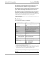
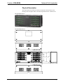
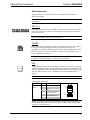
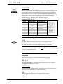
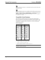
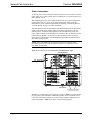
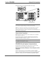
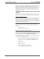
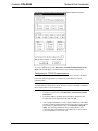
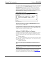
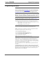
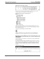
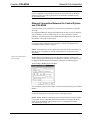
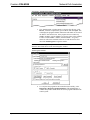
Crestron C2N-NPA8 Network Poll Accelerator Operations Guide This document was prepared and written by the Technical Documentation department at: Crestron Electronics, Inc. 15 Volvo Drive Rockleigh, NJ 07647 1-888-CRESTRON All brand names, product names and trademarks are the property of their respective owners. ©2004 Crestron Electronics, Inc. Crestron C2N-NPA8 Network Poll Accelerator Contents Network Poll Accelerator: C2N-NPA8 1 Introduction ............................................................................................................................... 1 Features and Functions ................................................................................................ 1 Specifications .............................................................................................................. 2 Physical Description.................................................................................................... 3 Compatible Control Systems ....................................................................................... 6 Industry Compliance ................................................................................................... 7 Setup .......................................................................................................................................... 7 Network Wiring........................................................................................................... 7 Mounting Options........................................................................................................ 8 Hardware Hookup ....................................................................................................... 9 C2N-NPA8-Control System Communications.......................................................... 13 System Monitoring/Diagnostics with the C2N-NPA8............................................... 17 Adding a C2N-NPA8 Without a Program ................................................................. 18 Programming Software ............................................................................................................ 19 Earliest Version Software Requirements for the PC ................................................. 19 Serial Connection Between the Control System and C2N-NPA8 ............................. 20 Ethernet Connection Between the Control System and C2N-NPA8 ......................... 21 Uploading and Upgrading........................................................................................................ 22 Communication Settings ........................................................................................... 22 Uploading a SIMPL Windows Program.................................................................... 24 Updating the Operating System................................................................................. 26 Problem Solving ...................................................................................................................... 27 Troubleshooting the C2N-NPA8 ............................................................................... 27 Further Inquiries ........................................................................................................ 30 Future Updates .......................................................................................................... 30 Software License Agreement................................................................................................... 31 Return and Warranty Policies .................................................................................................. 33 Merchandise Returns / Repair Service ...................................................................... 33 CRESTRON Limited Warranty................................................................................. 33 Operations Guide – DOC. 6087A Contents • i Crestron C2N-NPA8 Network Poll Accelerator Network Poll Accelerator: C2N-NPA8 Introduction Features and Functions The Crestron® Network Poll Accelerator (C2N-NPA8) is a device that maintains high data throughput and low data latency via Cresnet® when a large number of Cresnet devices communicate with a single 2-Series control system. When connected to select Crestron 2-Series control systems via a high speed serial or Ethernet connection, the C2N-NPA8 can provide reliable, high-speed communications between the control system and up to 252 Cresnet devices. Functional Summary • • • • • • Reliable, high-speed communications between select Crestron 2-Series control systems and up to 252 Cresnet devices Eight segments with four mini-Cresnet connectors per segment Independently operated segments provide fault tolerance should an individual segment fail Communicates with select 2-Series control systems via high-speed serial or 10/100 Base-T Ethernet (refer to “Compatible Control Systems” on page 6 for a list of compatible control systems) Console function to configure device settings and monitor diagnostics via DB-9 RS-232 connector Each Cresnet ID can be viewed with the Network Analyzer Placing a large amount of Cresnet devices on a control system can slow down polling time as each Cresnet device is polled sequentially by the control system. By breaking down the Cresnet system into segments, multiple segments can be polled simultaneously by the control system, hence improving response time. Similarly, high-traffic devices such as touchpanels, camera controls, and other devices require more network bandwidth as they transmit and receive larger amounts of data. By placing these devices on their own segments, other segments can be used for low-traffic devices such as wall keypads allowing Cresnet traffic to flow more efficiently. Operations Guide – DOC. 6087A Network Poll Accelerator: C2N-NPA8 • 1 Network Poll Accelerator Crestron C2N-NPA8 The C2N-NPA8 is typically recommended for networks with 20 or more devices (not including button panels). Consult with Crestron's True Blue Support to determine if a C2N-NPA8 would be beneficial to your system. The C2N-NPA8 is comprised of 32 Cresnet connectors spread over eight segments (NET A – NET H). These segments, along with the Cresnet port on the control system allow the connection of up to 252 Cresnet devices. The C2N-NPA8 is powered by a 24 VDC signal (from a 2-Series control system or Crestron power supply) applied to the 3-position mini-terminal block connector on either the NET A or NET B segments. Power is provided to the other segments by connecting jumper wires to each segment that requires power. Light Emitting Diodes (LEDs) indicate power and communication activity on each segment. For detailed information on the C2N-NPA8 input and output ports/connectors, refer to “Physical Description”. Specifications Specifications for the C2N-NPA8 are provided below. C2N-NPA8 Network Poll Accelerator Specifications SPECIFICATION DETAILS Power Requirements 10 Watts (0.42 Amp @ 24VDC) Supplied from control system or Crestron power supply Connectors/Ports PWR 8 – 3-position mini-terminal block connector. Provides 24V input (from power supply or powered segment) and 24V output (to segment on C2N-NPA8). One per segment. 32 – Cresnet 4-position mini-terminal block connectors, divided over 8 segments 1 – RJ45 10/100 Base-T Ethernet port 1 – DB9F PC Interface for console functions 1 – DB9F Interface for high-speed serial connection to control system NET LAN COMPUTER COM Cresnet Devices Supported 252 Firmware 1 V3105.CUZ or later 2,3 Control System Update Files 2-Series Control System MP2/MP2E/MC2E/MC2W Version C2.V3112.CUZ or later Version MP2.V3112.CUZ or later Environmental Temperature 41° to 113°F (5° to 45°C) Humidity 10% to 90% RH (non-condensing) Rack Space 3 Rack Units when used with optional C2N-RMAK Dimensions & Weight Height: Width: Depth: Weight: 5.19 in (13.18 cm) 13.25 in (33.66 cm) 3.42 in (8.69 cm) 1.91 lb (0.87 kg) 1. A control system can address 252 devices (NET IDs 03 to FE). 2. The latest versions can be obtained from the Downloads | Software Updates section of the Crestron website (www.crestron.com). Refer to NOTE below. 3. Crestron 2-Series control systems include the AV2, PAC2, PRO2, and RACK2. For a complete list of compatible control systems, refer to “Compatible Control Systems” on page 6. NOTE: Crestron software and any files on the website are for Authorized Crestron dealers and Crestron Authorized Independent Programmers (CAIP) only. New users may be required to register to obtain access to certain areas of the site (including the FTP site). 2 • Network Poll Accelerator: C2N-NPA8 Operations Guide – DOC. 6087A Crestron C2N-NPA8 Network Poll Accelerator Physical Description The C2N-NPA8 Network Poll Accelerator is housed in a black enclosure with labeling on the front panel. Refer to the following illustrations for a detailed view. C2N-NPA8 Physical View C2N-NPA8 Physical Views 12.25 in (31.12 cm) 4.00 in 5.19 in 3.00 in (7.62 cm) (10.16 cm) (13.18 cm) 12.75 in (32.39 cm) 3.42 in (8.69 cm) 13.25 in (33.66 cm) Operations Guide – DOC. 6087A Network Poll Accelerator: C2N-NPA8 • 3 Network Poll Accelerator Crestron C2N-NPA8 Ports/Connectors The ports/connectors on the top panel of the C2N-NPA8 are described in the following paragraphs. NOTE: Interface connectors for the PWR and NET ports are provided with the C2N-NPA8. NET A - H These eight segments provide 32 standard (24 Y Z G) Cresnet connectors (in groups of four) for Cresnet device connections. Each group of four supports 32 electrical Cresnet connections. NOTE: Although there are eight segments with four connectors each, a control system can only address 252 devices (03 through FE). POWER These connectors (quantity eight) are used to supply 24VDC power to each segment as well as providing a jumping point for powering another segment on the C2N-NPA8. To power the C2N-NPA8, 24VDC power must be supplied to a Cresnet connector or the power connector on NET A or NET B. For more details, refer to “Power Connections” on page 12. CAUTION: Use only Crestron power supplies for Crestron equipment. Failure to do so could cause equipment damage or void the Crestron warranty. LAN An 8-position RJ45 port is used for an Ethernet connection to a control system with Ethernet capabilities. Refer to the following table for the Ethernet connector signals and use an appropriate cable (not supplied). For information on connecting the LAN port to a control system, refer to “Configuring for TCP/IP Communications” on page 15. NOTE: Only one C2N-NPA8 can be connected to a control system. LAN Connector Specifications TYPE 8-Position RJ45 PIN 1 2 3 4 5 6 7 8 SIGNALS TD+ TDRD+ Connected to pin 5 Connected to pin 4 RDConnected to pin 8 Connected to pin7 1 8 1 8 Top Front NOTE: To determine which is pin 1 on the cable, hold the cable so that the end of the eight pin modular jack is facing away from you, with the clip down and copper side up. Pin 1 is on the far left. 4 • Network Poll Accelerator: C2N-NPA8 Operations Guide – DOC. 6087A Crestron C2N-NPA8 Network Poll Accelerator COMPUTER COMPUTER This DB9 (female) connector is used for console purposes. The C2N-NPA8’s Ethernet configuration settings and diagnostics can be accessed through this port. The port is modem compatible. The modem and/or PC program cable are not included. Supports baud rate of up to 115 Kb. Use with a standard DB9 straight through cable (Crestron cable number CNSP-587 or equivalent). Refer to the following table for the cable pinouts. For information on establishing serial communications with the C2N-NPA8, refer to “Establish a Serial Connection” on page 14. Standard DB9 Pin Assignments PIN # ABBREVIATION DESCRIPTION 1 N/A Not Connected 2 RD Receive Data 3 TD Transmit Data 4 N/A Not Connected 5 SG Signal Ground 6 N/A Not Connected 7 RTS Request To Send 8 CTS Clear To Send 9 N/A Not Connected Male DB9 Connector 1 2 3 6 7 4 8 5 9 Female DB9 Connector 5 4 9 3 8 2 7 1 6 NOTE: DTR, pin 4 and DSR, pin 6 are not normally used. COM This DB9 (female) bi-directional serial port is used for high-speed serial communication between a control system and the C2N-NPA8. Use with a DB9 straight through cable (Crestron cable number CNSP-587 or equivalent). NOTE: Crestron has successfully tested 50-foot serial cable runs without loss of signal quality. Cable runs in excess of 50 feet may be subject to signal degradation or errors as cable length increases. NOTE: Only one C2N-NPA8 can be connected to a control system. Indicators The C2N-NPA8 indicators are described in the following paragraphs. NET A - H The eight NET (A-H) activity LEDs illuminate when a device on the respective segment transmits and/or receives data. PWR (Power) This LED illuminates when a segment is connected to and receives 24 VDC power from an external power pack or a Crestron control system. LNK This LED illuminates when there is a connection to the LAN port. Operations Guide – DOC. 6087A Network Poll Accelerator: C2N-NPA8 • 5 Network Poll Accelerator Crestron C2N-NPA8 ACT This LED illuminates when there is communication (activity) at the LAN port with an Ethernet network. ERR This LED illuminates when an error condition is detected. This may be the result of hardware or software failure, or a programming error. To determine the actual error condition, examine the message available through the Viewport menu Functions | 2-Series | Error Log | Show Error Log. Refer to the note on page 22 for a definition of Viewport. Compatible Control Systems The C2N-NPA8 is compatible with several Crestron 2-series control systems. However, not all of the 2-series products are compatible with the C2N-NPA8. The following table lists 2-series control systems (that are currently available as of this writing) that are compatible with the C2N-NPA8 as well as the communication methods that can be used. Processor Compatibility PROCESSOR SERIAL ETHERNET AV2 YES C2N-DVP4DI NO CNX-DVP4 NO 1 YES 4 YES YES CP2 YES 3 CP2E YES 3 YES MC2E YES 3 YES MC2W YES 3 NO MP2 YES 3 NO MP2E YES 3 YES PAC2 NO PRO2 YES 1 NO YES 4 YES 4 QM-RMC NO NO QM-RMCRX NO NO RACK2 NO YES 4 1. COM ports C through F are poll accelerator-ready 2. COM ports A through C are poll accelerator-ready 3. COM ports A and B are poll accelerator-ready 4. Requires installation of C2ENET-1 or C2ENET-2 Ethernet card. NOTE: Control systems cannot use a plug in serial card (i.e. a C2COM-3) to communicate with the C2N-NPA8. 6 • Network Poll Accelerator: C2N-NPA8 Operations Guide – DOC. 6087A Crestron C2N-NPA8 Network Poll Accelerator Industry Compliance As of the date of manufacture, the C2N-NPA8 has been tested and found to comply with specifications for CE marking and standards per EMC and Radiocommunications Compliance Labelling (N11785). NOTE: This device complies with part 15 of the FCC rules. Operation is subject to the following two conditions: (1) this device may not cause harmful interference, and (2) this device must accept any interference received, including interference that may cause undesired operation. This equipment has been tested and found to comply with the limits for a Class B digital device, pursuant to part 15 of the FCC Rules. These limits are designed to provide reasonable protection against harmful interference in a residential installation. This equipment generates, uses and can radiate radio frequency energy and, if not installed and used in accordance with the instructions, may cause harmful interference to radio communications. However, there is no guarantee that interference will not occur in a particular installation. If this equipment does cause harmful interference to radio or television reception, which can be determined by turning the equipment off and on, the user is encouraged to try to correct the interference by one or more of the following measures: Reorient or relocate the receiving antenna. Increase the separation between the equipment and receiver. Connect the equipment into an outlet on a circuit different from that to which the receiver is connected. Consult the dealer or an experienced radio/TV technician for help. Setup Network Wiring CAUTION: Use only Crestron power supplies for Crestron equipment. Failure to do so could cause equipment damage or void the Crestron warranty. CAUTION: Provide sufficient power to the system. Insufficient power can lead to unpredictable results or damage to the equipment. Please use the Crestron Power Calculator (http://www.crestron.com/ dealer-tech_resources/power_calculator.asp) to help calculate how much power is needed for the system. CAUTION: Possible equipment damage if miswired. NOTE: When installing network wiring, refer to the latest revision of the wiring diagram(s) appropriate to your specific system configuration, available from the Operations Guide – DOC. 6087A Network Poll Accelerator: C2N-NPA8 • 7 Network Poll Accelerator Crestron C2N-NPA8 Downloads | Product Manuals | Wiring Diagrams section of the Crestron website (www.crestron.com). NOTE: Do not power up system until all wiring is verified. Care should be taken to ensure data (Y, Z) and power (24, G) connections are not crossed. NOTE: All network wiring must consist of two twisted-pairs. One twisted pair is the +24V conductor and the GND conductor and the other twisted pair is the Y conductor and the Z conductor. When calculating the wire gauge for a particular network run, the length of the run and the power factor of each network unit to be connected must be taken into consideration. If network units are to be daisy-chained on the run, the power factor of each network unit to be daisy-chained must be added together to determine the power factor of the entire chain. The length of the run in feet and the power factor of the run should be used in the following resistance equation to calculate the value on the right side of the equation. Resistance Equation R < 40,000 L x PF Where: R = Resistance (refer to table below). L = Length of run (or chain) in feet. PF = Power factor of entire run (or chain). The required wire gauge should be chosen such that the resistance value is less than the value calculated in the resistance equation. Refer to the following table. Wire Gauge Values RESISTANCE (R) WIRE GAUGE 4 16 6 18 10 20 15 22 13 Doubled CAT5 8.7 Tripled CAT5 NOTE: When daisy-chaining Cresnet units, strip the ends of the wires carefully to avoid nicking the conductors. Twist together the ends of the wires that share a pin on the network connector, and tin the twisted connection. Apply solder only to the ends of the twisted wires. Avoid tinning too far up the wires or the end becomes brittle. Insert the tinned connection into the Cresnet connector and tighten the retaining screw. Repeat the procedure for the other three conductors. Mounting Options Rack Mounting There is a rack mount kit for the C2N-NPA8 known as C2N-RMAK. For installation instructions, refer to the latest version of the Installation Guide (Doc. 6131) which is available from the Crestron website (www.crestron.com). CAEN Enclosure Mounting The C2N-NPA8 can also be installed in a Crestron Automation Enclosure (CAEN). To install the C2N-NPA8 in a CAEN enclosure, the CAEN Mounting Kit (CAEN8 • Network Poll Accelerator: C2N-NPA8 Operations Guide – DOC. 6087A Crestron C2N-NPA8 Network Poll Accelerator MK) must be used. For installation instructions, refer to the latest version of the Installation Guide (Doc. 6130) which is available from the Crestron website (www.crestron.com). Hardware Hookup Refer to the following hookup diagram and, aside from attaching power last, complete the connections in any order. Refer to “Network Wiring” on page 7 when making network connections. NOTE: To prevent overheating, do not operate this product in an area that exceeds the environmental temperature range listed in the table of specifications. Consideration must be given if installed in a closed or multi-unit rack assembly since the operating ambient temperature of the rack environment may be greater than the room ambient. Contact with thermal insulating materials should be avoided on all sides of the unit. NOTE: The maximum continuous current from equipment under any external load conditions shall not exceed a current limit that is suitable for the minimum wire gauge used in interconnecting cables. The ratings on the connecting unit's supply input should be considered to prevent overloading the wiring. Hookup Connections for the C2N-NPA8 TO CRESNET DEVICES FROM POWER SUPPLY OR POWERED SEGMENT AND TO UNPOWERED SEGMENT(S) 10/100 BASE-T ETHERNET TO CONTROL SYSTEM CONSOLE TO PC HIGH-SPEED SERIAL TO CONTROL SYSTEM NOTE: For the C2N-NPA8 to function, power must be applied to a power or Cresnet connector on either NET A or NET B. The C2N-NPA8 will not function if 24VDC power is not applied to either NET A or NET B’s power connectors. Cresnet Connections There are eight independent segments (labeled A through H), each with four Cresnet connectors wired in parallel. Each segment has a dedicated driver/receiver for Cresnet communication. The eight NET (A-H) activity LEDs illuminate when a device on the respective segment transmits data. Operations Guide – DOC. 6087A Network Poll Accelerator: C2N-NPA8 • 9 Network Poll Accelerator Crestron C2N-NPA8 Segments that are not in use or have devices that are not polled by a Crestron SIMPL Windows program are logically ‘disconnected’ from the other segments in operation. The LEDs for these segments are not illuminated. To properly configure a network using a C2N-NPA8, the network traffic should be balanced across the eight legs of the C2N-NPA8. NOTE: The tips described below can be used as a starting point for balancing the network traffic on most networks. Contact Crestron’s True Blue Technical Support to determine the best configuration for your network. Configuration Tips • Place ALL Cresnet devices on the segments of the poll accelerator and nothing on the control system’s Cresnet bus. • Group all devices by device type and assign consecutive Cresnet ID numbers. • Place devices on sequential segments of the poll accelerator in order of Cresnet ID number (i.e. ID 03 on segment A, ID 04 on segment B, etc.) Since the Cresnet network is polled by the control system in numeric order, the control system will talk to different segments, allowing each segment to process commands that overlap, instead of having to wait for the completion of one command before going on to the next command. Example The following example is provided to show how a large amount of network devices may be connected to the C2N-NPA8 for optimum performance. A system has the following network devices: • Five TPS-3000L touchpanels. The touchpanels have been assigned with Cresnet ID numbers 03 through 07. • Five CT-1000 touchpanels. The touchpanels have been assigned with Cresnet ID numbers 08 through 0C. • Five TPS-4500 touchpanels. The touchpanels have been assigned with Cresnet ID numbers 0D through 11. • Two C2N-IIF intercom interfaces. The interfaces have been assigned with Cresnet ID numbers 12 and 13. • Three C2N-TXM satellite radio tuners. The tuners have been assigned Cresnet ID number 14 through 16. Using the configuration tips, connect the network devices as shown in the following diagram. 10 • Network Poll Accelerator: C2N-NPA8 Operations Guide – DOC. 6087A Crestron C2N-NPA8 Network Poll Accelerator Configuration Example NOTE: 24 VDC power must be supplied to the C2N-NPA8 by the PWR connector on segment A or B. The control system must communicate with the poll accelerator via serial or Ethernet communications. Operations Guide – DOC. 6087A Network Poll Accelerator: C2N-NPA8 • 11 Network Poll Accelerator Crestron C2N-NPA8 Power Connections To provide power to the C2N-NPA8, connect 24VDC power from either a Crestron power supply or a 2-Series control system to a PWR port or a Cresnet connector on either segment A or B. When applying power, the same considerations used in any Cresnet configuration (with regard to a device’s power factor and required power supply for proper distribution of power), should be applied when connecting a C2N-NPA8. Refer to “Network Wiring” on page 7 for more information. The C2N-NPA8 can be powered with the C2N-SPWS300 External 300 Watt Power Supply. This power supply features eight power outputs, which can be used to control power to each of the eight segments on the C2N-NPA8. By wiring each power segment from the C2N-SPWS300 to a segment on the C2N-NPA8 (as shown in the following diagram), each segment on the C2N-NPA8 can be activated or deactivated by controlling the C2N-SPWS300 through additional programming in the control system program. NOTE: If the C2N-SPWS300 is being used to power each segment on the C2N-NPA8, power must always be applied to segment A or segment B on the C2N-NPA8 for activation. Wiring Power Connectors on C2N-NPA8 with C2N-SPWS300 Power Supply C2N-SPWS300 100 - 240 VAC, 4 A, 50/60 Hz C2N-NPA8 To Control System via TCP/IP or Serial Communications Alternatively, a single power source (such as Crestron’s CNPWS-75) can be used to provide power to the C2N-NPA8. Additional segments on the C2N-NPA8 may be powered by connecting a jumper wire from a powered segment’s PWR port to an unpowered segment’s PWR port as shown in the following diagram. 12 • Network Poll Accelerator: C2N-NPA8 Operations Guide – DOC. 6087A Crestron C2N-NPA8 Network Poll Accelerator Wiring Power Connectors on C2N-NPA8 with CNPWS-75 Power Supply CNPWS-75 C2N-NPA8 To Control System via TCP/IP or Serial Communications CAUTION: Use only Crestron power supplies for Crestron equipment. Failure to do so could cause equipment damage or void the Crestron warranty. NOTE: If a Cresnet device connected to a powered segment has its own power source, remove the 24V line from the Cresnet connector on the C2N-NPA8. Although equipment damage is unlikely, Crestron does not recommend applying two power sources to the same segment. Communication Connections When using a PC for console operations on the C2N-NPA8, refer to “Establish a Serial Connection” on page 14. The C2N-NPA8 can also be connected to compatible control systems that are equipped with an Ethernet port. Refer to “TCP/IP Communications Between a Control System and the C2N-NPA8” on page 14. NOTE: For a list of control systems that are compatible with the C2N-NPA8, refer to “Compatible Control Systems” on page 6. C2N-NPA8-Control System Communications The C2N-NPA8 can communicate with a control system over serial or TCP/IP communication. Only one method of communication can be used. Serial Communications Between a Control System and the C2N-NPA8 If a direct connection from a PC to the C2N-NPA8 is required for uploading firmware or performing diagnostics, follow the steps described in “Establish a Serial Connection” on page 14. If the C2N-NPA8 firmware is to be upgraded through a connection to a control system, refer to “Uploading and Upgrading” on page 22. Operations Guide – DOC. 6087A Network Poll Accelerator: C2N-NPA8 • 13 Network Poll Accelerator Crestron C2N-NPA8 If using a serial connection for communications between the control system and the C2N-NPA8, connect a straight through serial cable (Crestron cable number CNSP-587 or equivalent) from a compatible COM port on the control system to the COM port on the C2N-NPA8. All serial communication parameters between the control system and the C2N-NPA8 are automatically configured by the program stored on the control system. TCP/IP Communications Between a Control System and the C2N-NPA8 If the control system is to communicate with the C2N-NPA8 over TCP/IP, a serial connection must first be established to configure the C2N-NPA8 TCP/IP settings. Establish a Serial Connection Connect the COMPUTER port on the C2N-NPA8 to one of the COM ports (usually COM 1) on the PC. Use a straight through serial cable (Crestron cable number CNSP-587 or equivalent) with a DB9 male connector on one end and a DB9 female connector on the other. Most commercially available cables are acceptable. Refer to “COMPUTER” on page 5 for pinout details. NOTE: For laptops and other PCs without a built-in RS-232 port, Crestron recommends the use of PCMCIA cards, rather than USB-to-serial adapters. If a USB-to-serial adapter must be used, Crestron has tested the following devices with good results: I/O Gear GUC232A Keyspan USA-19QW (Discontinued) Results may vary depending on the computer being used. Other models, even from the same manufacturer, may not yield the same results. Open the Crestron Viewport and click Setup | Communication Settings to display the “Port Settings” window. Then click RS-232 as the connection type. The PC communication settings specified here should match the protocol that the C2N-NPA8 uses. The settings are as follows: • Port = COM 1 through COM 8. Select the correct COM port on the PC. • Baud rate = 115200 (You can set the PC and the control system to a different baud rate, by using the Functions | Set Baud Rate command. • Parity = None. • Number of data bits = 8. • Number of stop bits = 1. • Hardware handshaking (RTS/CTS) enabled. • Software handshaking (XON/XOFF) not enabled. 14 • Network Poll Accelerator: C2N-NPA8 Operations Guide – DOC. 6087A Crestron C2N-NPA8 Network Poll Accelerator “Port Settings” Window: Settings for RS-232 Communication with the C2N-NPA8 To verify communication, click Diagnostics | Establish Communications (Find Rack). This should display a window that gives the COM port and baud rate. Configuring for TCP/IP Communications Once communications have been established between the PC and the C2N-NPA8, perform the following procedure to configure the C2N-NPA8 for TCP/IP communications. NOTE: The terms used in the following steps are explained in detail in the Crestron e-Control Reference Guide (Doc. 6052). The latest version is available as a PDF on the Crestron website (www.crestron.com). Operations Guide – DOC. 6087A 1. From the Viewport menu, click Functions | Set Control System IP Information. 2. Enter the IP address, IP Mask, Router IP address, Hostname, and Domain name in the applicable fields and click OK. 3. After saving the IP address, an entry must be added to the C2N-NPA8 IP table to enable communications between the control system and the C2N-NPA8. To add an IP table entry, click Functions | Setup IP Table. The following illustration shows a sample IP table for a C2N-NPA8 that will communicate via Ethernet to a 2-Series control system at IP address 192.168.125.165. Network Poll Accelerator: C2N-NPA8 • 15 Network Poll Accelerator Crestron C2N-NPA8 C2N-NPA8 IP Table 4. Click Add and enter the IP ID and IP address/Hostname of the control system in the relevant fields. Set as Master must be checked to indicate that the C2N-NPA8 is controlled by the device using the IP address. Select Connect Using TCP and click OK. NOTE: The “IP Table Setup” window allows more than one entry to be entered in the C2N-NPA8’s IP table. However, the poll accelerator will only read the first entry. All other entries will be ignored. 5. Click Send to send the IP table to the C2N-NPA8. If an entry does not already exist, add a corresponding entry for the C2N-NPA8 in the control system’s IP table. 6. Create an entry in the control system’s IP table listing the IP address of the C2N-NPA8. NOTE: Port number 41791 must be accessible to the control system for communication with the C2N-NPA8. NOTE: If a control system program uses a TCP/IP Client symbol or TCP/IP Server symbol, port number 41791 cannot be specified for either symbol if a C2N-NPA8 is in the control system program. NOTE: The default port number assigned by Viewport should not be changed when configuring the IP tables on the control system and the C2N-NPA8. NOTE: If an IP table is defined in the C2N-NPA8, then serial communication between the C2N-NPA8 and a control system is disabled. To enable high-speed serial communications, remove the IP table entry from the C2N-NPA8’s IP table. TCP/IP communications between the C2N-NPA8 and the control system will be disabled while serial communication will be enabled. Once the IP settings have been defined in the IP tables of the C2N-NPA8 and the control system, the C2N-NPA8 can communicate with the control system using a TCP/IP connection. 16 • Network Poll Accelerator: C2N-NPA8 Operations Guide – DOC. 6087A Crestron C2N-NPA8 Network Poll Accelerator Connecting the C2N-NPA8 to the Control System via Ethernet To enable TCP/IP communication, use CAT5 straight through cables with 8-pin RJ45 connectors to connect the LAN port on the C2N-NPA8 and the LAN port on the control system to an Ethernet hub. Alternatively, you can use a CAT5 crossover cable to connect the LAN port on the control system directly to the LAN port on the C2N-NPA8 without using a hub. The following figure illustrates pinouts for straight through and crossover RJ45 cables. Pins 4, 5, 7, and 8 are not used. RJ45 Pinouts Once the cable connections are made, verify communications by opening the Crestron Viewport and clicking Setup | Communication Settings on the menu to display the “Port Settings” window. Select TCP/IP as the connection type and enter the IP address of the C2N-NPA8. Click OK to connect to the C2N-NPA8 over TCP/IP. “Port Settings” Window To verify communication, click Diagnostics | Establish Communications (Find Rack). This should display a window that gives the IP address and port number. If communications cannot be established between the C2N-NPA8 and a control system, refer to “Troubleshooting Communications” on page 28. System Monitoring/Diagnostics with the C2N-NPA8 A C2N-NPA8 in a Cresnet system provides improved troubleshooting abilities for monitoring Cresnet devices. A common problem in building a system is the use of devices with identical Cresnet IDs. In a system without a C2N-NPA8, Cresnet IDs that are duplicated are not reported by the system when using the REPORTCRESNET command in Viewport. A system with a C2N-NPA8 recognizes the existence of a duplicated Cresnet ID if the devices are on different Operations Guide – DOC. 6087A Network Poll Accelerator: C2N-NPA8 • 17 Network Poll Accelerator Crestron C2N-NPA8 legs of the C2N-NPA8. If the duplicated IDs are on the same leg, the Cresnet ID will not be displayed when using the REPORTCRESNET command in Viewport. The REPORTCRESNET command lists each Cresnet ID in the system along with identifying the C2N-NPA8 segment where the device is located. Devices that are connected to the control system’s Cresnet connector (not on the C2N-NPA8) are listed without identifying a segment. The illustration below shows a REPORTCRESNET report indicating where devices are located on the C2N-NPA8. REPORTCRESNET with C2N-NPA8 The C2N-NPA8 console can be accessed through the Viewport utility to perform diagnostics. At the control system prompt, type PASSTHRU NPA. For a list of available commands, type HELP ALL. For further diagnostics, the Network Analyzer tool that is built into SIMPL Windows can be used to analyze the signal quality of each Cresnet ID in a system. For more information on how to use the network analyzer, refer to the SIMPL Windows help file and use the index to search for "Network Analyzer". Adding a C2N-NPA8 Without a Program If a control system has been rebooted and it does not have a program that contains a C2N-NPA8, it must be told via console command that a C2N-NPA8 is present. If using serial communications, open Viewport (while connected to a control system) and type: NPA ADD PORT Y Where “Y” is the letter designating the serial port on the control system For example, NPA ADD PORT C installs the C2N-NPA8 on port C of a control system). If using TCP/IP communications, type: NPA ADD IPID 0xYY Where “YY” is the IP ID in the control system’s IP table when using TCP/IP communications. For example, NPA ADD IPID 0x03 installs the C2N-NPA8 at IP ID 03. NOTE: The C2N-NPA8 must be defined in the control system’s IP table and the control system must be listed in the C2N-NPA8’s IP table before using the NPA ADD IPID command. For more information on console commands, refer to the latest version of the 2Series Console Commands Reference Guide (Doc. 6002), available from the Downloads | Product Manuals section of the Crestron website (www.crestron.com). 18 • Network Poll Accelerator: C2N-NPA8 Operations Guide – DOC. 6087A Crestron C2N-NPA8 Network Poll Accelerator Programming Software Have a question or comment about Crestron software? Answers to frequently asked questions (FAQs) can be viewed in the Online Help section of the Crestron website (www.crestron.com). To post your own question or view questions you have submitted to Crestron’s True Blue Support, log in at http://support.crestron.com. First-time users will need to establish a user account. Earliest Version Software Requirements for the PC NOTE: Crestron recommends that you use the latest software to take advantage of the most recently released features. The latest software is available from the Downloads | Software Updates section of the Crestron website (www.crestron.com). The following are the earliest useable software version requirements for the PC: • SIMPL Windows version 2.04.14 or later with Library Update 232 or later. Requires SIMPL+ Cross Compiler version 1.1. • Crestron Database version 16.0.0 or later. NOTE: The following assumes that the reader has knowledge of SIMPL Windows. If not, refer to the extensive help information provided with the software. NOTE: The following are acceptable file extensions for programs that include a C2N-NPA8, developed for specific control system types: .smw .spz .usp .ush .umc projectname.smw (source file) projectname.spz (compiled file for 2-series) projectname.usp (source code module for SIMPL+) projectname.ush (compiled SIMPL+ file) projectname.umc (user macro) NOTE: In the following, the PRO2 control system is used. SIMPL Windows is Crestron's primary software for programming Crestron control systems. It provides a well-designed graphical environment with a number of workspaces (i.e., windows) in which a programmer can select, configure, program, test, and monitor a Crestron control system. SIMPL Windows offers drag and drop functionality in a familiar Windows environment. This section explains how to create a SIMPL Windows program that includes the C2N-NPA8. Configuration Manager is where programmers “build” a Crestron control system by selecting hardware from the Device Library. In Configuration Manager, drag the PRO2 from the Control Systems folder of the Device Library and drop it in the upper pane of the System Views. The PRO2 with its associated communication ports is displayed in the System Views upper pane. Operations Guide – DOC. 6087A Network Poll Accelerator: C2N-NPA8 • 19 Network Poll Accelerator Crestron C2N-NPA8 PRO2 System View with C2ENET-1 Installed The System Views lower pane displays the PRO2 system tree. This tree can be expanded to display and configure the communications ports. Expanded PRO2 (with C2ENET-1 Installed) System Tree When a C2N-NPA8 is added to a system in Configuration Manager, the Cresnet Units icon in System Views changes as shown in the following diagram to indicate that a C2N-NPA8 is present. “Cresnet Units” Icon Indicating a C2N-NPA8 is Installed Adding a C2N-NPA8 to a 2-series control system is as easy as dragging and dropping the device into the appropriate device slot in the 2-Series system tree. Serial Connection Between the Control System and C2N-NPA8 If the C2N-NPA8 is to be connected to a control system via serial communications, perform the following: In Configuration Manager, drag the C2N-NPA8 from the Serial Drivers (General) folder of the Device Library and drop it onto a compatible serial port of the control system. Click Yes when prompted (refer to the following diagram) to replace the serial driver for that port. SIMPL Windows displays the C2N-NPA8 in the target serial port. Configuration Manager Prompt 20 • Network Poll Accelerator: C2N-NPA8 Operations Guide – DOC. 6087A Crestron C2N-NPA8 Network Poll Accelerator NOTE: For a list of control systems that can communicate with the C2N-NPA8, refer to “Compatible Control Systems” on page 6. Review the notes to determine which serial ports on a control system can be used with the C2N-NPA8 if using serial communications. Ethernet Connection Between the Control System and C2N-NPA8 If the C2N-NPA8 is to be connected to a control system via Ethernet, perform the following: In Configuration Manager, drag the C2N-NPA8 from the Ethernet Control Modules | Ethernet Modules (Crestron) folder of the Device Library and drop it onto the C2ENET-1 slot of the control system. SIMPL Windows displays the C2N-NPA8 in the C2ENET-1 slot of the control system. NOTE: Ethernet devices can only be added to Ethernet-equipped control systems. For a list of control systems that can communicate with the C2N-NPA8, refer to “Compatible Control Systems” on page 6. NOTE: An IP table entry for the control system must exist on the C2N-NPA8’s IP table. Refer to “Configuring for TCP/IP Communications” on page 15 for more information. Setting the IP Information in Device Settings Double-click the C2N-NPA8 icon to open the “Device Settings” window. This window displays the C2N-NPA8 device information. Select the IP Net Address tab to change the IP ID and other IP information as shown in the following figure. “Device Settings” Window for the C2N-NPA8 Any information entered in this window is used to create the control system’s default IP table. NOTE: The control system’s IP table must list the C2N-NPA8’s IP address. This can be done using the Device Settings window or through Viewport. NOTE: SIMPL Windows automatically chooses the IP ID values of devices added to a program. Always ensure that the hardware and software settings of the IP ID match. For IP ID hardware settings details, refer to “Configuring for TCP/IP Communications” on page 15. Operations Guide – DOC. 6087A Network Poll Accelerator: C2N-NPA8 • 21 Network Poll Accelerator Crestron C2N-NPA8 Uploading and Upgrading Assuming a PC is properly connected to the entire system, Crestron programming software allows the programmer to upload programs and projects after their development to the system and network devices. However, there are times when the files for the program and projects are compiled and not uploaded. Instead, compiled files may be distributed from programmers to installers, from Crestron to dealers, etc. Even firmware upgrades are available from the Crestron website as new features are developed after product releases. In those instances, one has the option to upload via the programming software or to upload and upgrade via the Crestron Viewport. NOTE: The Crestron Viewport is available as a pull-down command from SIMPL Windows and VT Pro-e (Tools | Viewport) or as a standalone utility. The Viewport utility accomplishes multiple system tasks, primarily via an RS-232 or TCP/IP connection between the control system and a PC. It is used to observe system processes, upload new operating systems and firmware, change system and network parameters, and communicate with network device consoles and touchpanels, among many other tasks. Viewport can also function as a terminal emulator for generic file transfer. All of these functions are accessed through the commands and options in the Viewport menus. Therefore, for its effectiveness as a support and diagnostic tool, the Crestron Viewport may be preferred over development tools when uploading programs and projects. The following sections define how one would upload a SIMPL Windows program containing a C2N-NPA8 or upgrade the firmware of the C2N-NPA8. However, before attempting to upload or upgrade, it is necessary to establish communications with the control system. Communication Settings NOTE: For laptops and other PCs without a built-in RS-232 port, Crestron recommends the use of PCMCIA cards, rather than USB-to-serial adapters. If a USB-to-serial adapter must be used, Crestron has tested the following devices with good results: I/O Gear GUC232A Keyspan USA-19QW (Discontinued) Results may vary depending on the computer being used. Other models, even from the same manufacturer, may not yield the same results. The procedure in this section provides details for RS-232 communication between the PC and the control system. If TCP/IP communication is preferred, consult the latest version of the Crestron e-Control Reference Guide (Doc. 6052) or the respective Operations Guide for the control system. These documents are available from the Downloads | Product Manuals section of the Crestron website (www.crestron.com). Refer to the figure on the next page for a typical connection diagram when uploading files. 22 • Network Poll Accelerator: C2N-NPA8 Operations Guide – DOC. 6087A Crestron C2N-NPA8 Network Poll Accelerator Typical Connection Diagram when Uploading 1. Open the Crestron Viewport. Either launch the stand-alone version of Viewport or start SIMPL Windows and from the menu bar, select Tools | Viewport. 2. Refer to the following figure after this step. From the Viewport menu, select Setup | Communications settings (alternatively, press Alt+D) to open the “Port Settings” window. Setup | Communications Settings Command 3. Operations Guide – DOC. 6087A Select RS-232 as the connection type. Verify that an available COM port (COM 1 is shown after this step) is selected, and that all communication parameters and necessary options from the “Port Settings” window are selected as shown after this step. Click the OK button to save the settings and close the window. Network Poll Accelerator: C2N-NPA8 • 23 Network Poll Accelerator Crestron C2N-NPA8 “Port Settings” Window NOTE: The parameters shown in the illustration above are the port settings for a 2Series control system. Consult the Operations Guide for the control system being used for exact parameter selection. If using a TCP/IP connection, select TCP/IP (Crestron Terminal Protocol) and enter the IP information for the control system. Click the OK button to save the settings and close the window. 4. To verify communication, select Diagnostics | Establish Communications (Find Rack). This should display a window that gives the COM port and baud rate. If communication cannot be established, refer to the “Troubleshooting Communications” section in the respective Operations Guide for the control system. Uploading a SIMPL Windows Program A control system source file has the extension .smw. A compiled SIMPL Windows file has the extension .spz for a 2-Series control system. Once communication with the control system has been established, a SIMPL Windows program containing a C2N-NPA8 can be uploaded to the control system using SIMPL Windows or the Crestron Viewport. Upload via SIMPL Windows 1. Start SIMPL Windows. 2. Select File | Open to view the “Open” window, navigate to the SIMPL Window file (.smw), and click Open. 3. Select Project | Transfer Program. Upload via Crestron Viewport 1. Verify that the procedure for “Communication Settings” that begins on page 22 has been performed. 2. As shown after this step, select File Transfer | Send Program (alternatively, press Alt+P) from the Viewport menu. 24 • Network Poll Accelerator: C2N-NPA8 Operations Guide – DOC. 6087A Crestron C2N-NPA8 Network Poll Accelerator File Transfer | Send Program Command 3. The “Send Program” window appears, as shown after this step. Click Browse, locate the compiled file (.spz for PRO2) and click Open. This will display the program's header information and enable one or both of the What to Send check boxes. If the program does not contain any SIMPL+ modules, only the SIMPL Program check box will be enabled. If it does contain SIMPL+ modules, then the SIMPL+ Program(s) check box will also be enabled. Select one or both check boxes and then click Send Program to begin the transfer. NOTE: Refer to the respective Operations Guide for the control system for details about the other fields shown on the “Send Program” window. “Send Program” Window 4. Operations Guide – DOC. 6087A To verify that the program has been transferred successfully, select Diagnostics | Report Program Information. This should display a window that provides details about the current program loaded into the control system. Network Poll Accelerator: C2N-NPA8 • 25 Network Poll Accelerator Crestron C2N-NPA8 Updating the Operating System The operating system files for the C2N-NPA8 have a .cuz extension. You can obtain .cuz updates (when available) from the software downloads area of the Crestron website. To download an update, click the .cuz file and choose the Save to Disk option, then specify the directory where the update will be stored. NOTE: In some cases Microsoft's Internet Explorer may append a .zip extension to a downloaded .cuz file. For example, a file called "c2n-npa8.v3105.cuz" may appear as "c2n-npa8.v3105.cuz.zip." If this happens, rename the file, removing the .zip extension. NOTE: Even though the C2N-NPA8 uses a .CUZ file, it cannot be loaded with a SIMPL Windows or SIMPL+® program To upload the new .cuz to the C2N-NPA8: 1. Open Viewport and connect to the C2N-NPA8 over a serial (from the COM port on the PC to the COMPUTER port on C2N-NPA8) or TCP/IP connection as described in “Communication Settings” on page 22. 2. Select File Transfer | Update Control System or press ALT + O. 3. Browse to the .cuz file and click Open to start the transfer. 4. After the transfer is complete, the C2N-NPA8 will automatically reboot. To confirm the transfer, click Diagnostics | Check Ops Version. The Viewport console should display the new .cuz version number. 26 • Network Poll Accelerator: C2N-NPA8 Operations Guide – DOC. 6087A Crestron C2N-NPA8 Network Poll Accelerator Problem Solving Problems may occur with the 2-Series automation control system itself or there may be serial communication difficulties with other devices connected to the control system. The next two sections address possible problem solving tools or procedures for each situation. Troubleshooting the C2N-NPA8 The following table provides corrective action for possible trouble situations. If further assistance is required, please contact a Crestron customer service representative. C2N-NPA8 Troubleshooting TROUBLE POSSIBLE CAUSE(S) CORRECTIVE ACTION Unexpected response from control system. Network devices are not communicating to the control system. From the Viewport, poll the network (F4) to verify communication. Intermittent communication with Cresnet device. Possible wiring fault. Use Network Analyzer to check connection with Cresnet device. PWR LED does not illuminate. Segment is not receiving power. Verify that 24V power is applied to either segment A or B of the C2N-NPA8. Verify that the segment is connected to a powered segment. ERR LED illuminates. Hardware failure, software failure, or programming error. Verify that the hardware configuration matches software configuration. Poll the network (F4) from the Viewport; check error log for SIMPL, SIMPL+ program reload errors. C2N-NPA8 does not communicate with control system. Used wrong serial port. Verify that a Poll-Acceleratorcompatible port is used if using serial communications (refer to chart on page 6 for details). Serial cable miswired. Verify that serial cable is wired correctly if using serial communications. Serial cable pins do not make proper contact with DB9 socket. Remove the two standoffs on either side of the DB9 socket. Incorrect IP information. Verify correct IP information on control system and C2N-NPA8. Incorrect Network Cable. Use cable with pinouts described in “Serial Communications Between a Control System and the C2N-NPA8” on page 13 or Connecting the C2N-NPA8 to the Control System via Ethernet” on page17. Incorrect power supply. Use power from a Crestron power source. Various. Refer to the “Troubleshooting NonFunctioning Units” procedure following this table. System does not function. Operations Guide – DOC. 6087A Network Poll Accelerator: C2N-NPA8 • 27 Network Poll Accelerator Crestron C2N-NPA8 Troubleshooting Communications Use the following checklist if communications cannot be established with the C2N-NPA8. 1. Verify that you are using the correct cables. As described previously, an RS-232 connection requires a straight-through serial cable. That is, pin 1 on one end is connected to pin 1 on the other end. Pin 2 connects to pin 2, etc. With a TCP/IP connection, you must use a CAT5 cable with 8-pin RJ45 connectors. 2. With a serial connection, verify that the correct COM port on the PC has been selected. Some computers have more than one COM port; some may be internal (e.g., for a modem). Consult the manufacturer’s documentation for further information about the COM ports on your PC. 3. Check the ERR LED indicator on the C2N-NPA8. If this LED is illuminated before a program is loaded, examine the error log through the Viewport menu Functions | 2-Series | Error Log | Show Error Log. 4. Correct any problems indicated by the error log, i.e. connect cables, verify Ethernet parameters, reconfigure Cresnet IDs to eliminate duplicates, etc. 5. Clear the error log. If the ERR LED illuminates again, unplug the unit and reapply power after a few seconds. If the LED illuminates again, or if communication still cannot be established, contact Crestron customer service. Troubleshooting Non-Functioning Units If after reviewing the troubleshooting chart on page 27, the C2N-NPA8 is still not functioning, reinstall the operating system file by performing the following procedure. 1. Connect a DB9 straight through RS-232 cable between the C2N-NPA8 and a PC. Refer to “Establish a Serial Connection” on page 14 for more information. 2. Open Viewport and select Setup | Communication Settings to open the “Port Settings” window. 3. In the window, select RS-232 (Connection Type), 57600 (Baud Rate), N (Parity), 8 (Data Bits) and 1 (Stop Bits) and click OK. 4. Power down the C2N-NPA8. 5. While powering up the C2N-NPA8, press and hold ALT + K on the keyboard until the following text (or similar) appears in Viewport: System Monitor [v1.001 (0001)] 12-19-01 16:25:23 32 MB RAM, 4MB FLASH CS> NOTE: After this, you can increase the baud rate to 115200 (for faster communication) by pressing F8 on the keyboard and then selecting 115200 from the “Set Baud Rate” window. 28 • Network Poll Accelerator: C2N-NPA8 Operations Guide – DOC. 6087A Crestron C2N-NPA8 Network Poll Accelerator 6. Press ALT + O (not zero) on the keyboard. The “Open” window appears. 7. Find and select the correct CSU file (*.CSU, extracted from the .CUZ file using WinZip or other ZIP file extraction tool) and click Open. NOTE: System Monitor cannot be used to upload a .CUZ file. Only the .CSU file can be used. Once “Completed Successfully” appears in Viewport, type quit at the Viewport prompt and press Enter. Network Analyzer To assist with troubleshooting, the unit contains Crestron’s patent-pending network analyzer to continuously monitor the integrity of the Cresnet network for wiring faults and marginal system performance or other network errors. For more information on how to use the network analyzer, refer to the SIMPL Windows help file and use the index to search for "Network Analyzer". NOTE: The Network Analyzer can be used when directly connected to the C2N-NPA8 or when connected to Cresnet via a control system. NOTE: The C2N-NPA8’s network analyzer will monitor the devices connected in the network, not the segments of the C2N-NPA8. Operations Guide – DOC. 6087A Network Poll Accelerator: C2N-NPA8 • 29 Network Poll Accelerator Crestron C2N-NPA8 Further Inquiries If, after reviewing this Operations Guide for the C2N-NPA8, you cannot locate specific information or have questions, please take advantage of Crestron's award winning customer service team in your area. Dial one of the following numbers. • In the US and Canada, call Crestron's corporate headquarters at 1-888-CRESTRON [1-888-273-7876]. • In Europe, call Crestron International at +32-15-50-99-50. • In Asia, call Crestron Asia at +852-2341-2016. • In Latin America, call Crestron Latin America at +5255-5093-2160. • In Australia and New Zealand, call Crestron Pacific at +613-9480-2999. You can also log onto the online help section of the Crestron website (www.crestron.com) to ask questions about Crestron products. First-time users will need to establish a user account to fully benefit from all available features. Future Updates As Crestron improves functions, adds new features, and extends the capabilities of the C2N-NPA8, additional information may be made available as manual updates. These updates are solely electronic and serve as intermediary supplements prior to the release of a complete technical documentation revision. Check the Crestron website (www.crestron.com) periodically for manual update availability and its relevance. Updates are available from the Downloads | Product Manuals section and are identified as an “Addendum” in the Download column. 30 • Network Poll Accelerator: C2N-NPA8 Operations Guide – DOC. 6087A Crestron C2N-NPA8 Network Poll Accelerator Software License Agreement This License Agreement (“Agreement”) is a legal contract between you (either an individual or a single business entity) and Crestron Electronics, Inc. (“Crestron”) for software referenced in this guide, which includes computer software and, as applicable, associated media, printed materials, and “online” or electronic documentation (the “Software”). BY INSTALLING, COPYING, OR OTHERWISE USING THE SOFTWARE, YOU REPRESENT THAT YOU ARE AN AUTHORIZED DEALER OF CRESTRON PRODUCTS OR A CRESTRON AUTHORIZED INDEPENDENT PROGRAMMER AND YOU AGREE TO BE BOUND BY THE TERMS OF THIS AGREEMENT. IF YOU DO NOT AGREE TO THE TERMS OF THIS AGREEMENT, DO NOT INSTALL OR USE THE SOFTWARE. IF YOU HAVE PAID A FEE FOR THIS LICENSE AND DO NOT ACCEPT THE TERMS OF THIS AGREEMENT, CRESTRON WILL REFUND THE FEE TO YOU PROVIDED YOU (1) CLICK THE DO NOT ACCEPT BUTTON, (2) DO NOT INSTALL THE SOFTWARE AND (3) RETURN ALL SOFTWARE, MEDIA AND OTHER DOCUMENTATION AND MATERIALS PROVIDED WITH THE SOFTWARE TO CRESTRON AT: CRESTRON ELECTRONICS, INC., 15 VOLVO DRIVE, ROCKLEIGH, NEW JERSEY 07647, WITHIN 30 DAYS OF PAYMENT. LICENSE TERMS Crestron hereby grants You and You accept a nonexclusive, nontransferable license to use the Software (a) in machine readable object code together with the related explanatory written materials provided by Creston (b) on a central processing unit (“CPU”) owned or leased or otherwise controlled exclusively by You, and (c) only as authorized in this Agreement and the related explanatory files and written materials provided by Crestron. If this software requires payment for a license, you may make one backup copy of the Software, provided Your backup copy is not installed or used on any CPU. You may not transfer the rights of this Agreement to a backup copy unless the installed copy of the Software is destroyed or otherwise inoperable and You transfer all rights in the Software. You may not transfer the license granted pursuant to this Agreement or assign this Agreement without the express written consent of Crestron. If this software requires payment for a license, the total number of CPU’s on which all versions of the Software are installed may not exceed one per license fee (1) and no concurrent, server or network use of the Software (including any permitted back-up copies) is permitted, including but not limited to using the Software (a) either directly or through commands, data or instructions from or to another computer (b) for local, campus or wide area network, internet or web hosting services; or (c) pursuant to any rental, sharing or “service bureau” arrangement. The Software is designed as a software development and customization tool. As such Crestron cannot and does not guarantee any results of use of the Software or that the Software will operate error free and You acknowledge that any development that You perform using the Software or Host Application is done entirely at Your own risk. The Software is licensed and not sold. Crestron retains ownership of the Software and all copies of the Software and reserves all rights not expressly granted in writing. OTHER LIMITATIONS You must be an Authorized Dealer of Crestron products or a Crestron Authorized Independent Programmer to install or use the Software. If Your status as a Crestron Authorized Dealer or Crestron Authorized Independent Programmer is terminated, Your license is also terminated. You may not rent, lease, lend, sublicense, distribute or otherwise transfer or assign any interest in or to the Software. You may not reverse engineer, decompile, or disassemble the Software. You agree that the Software will not be shipped, transferred or exported into any country or used in any manner prohibited by the United States Export Administration Act or any other export laws, restrictions or regulations (“Export Laws”). By downloading or installing the Software You (a) are certifying that You are not a national of Cuba, Iran, Iraq, Libya, North Korea, Sudan, or Syria or any country to which the United States embargoes goods (b) are certifying that You are not otherwise prohibited from receiving the Software and (c) You agree to comply with the Export Laws. If any part of this Agreement is found void and unenforceable, it will not affect the validity of the balance of the Agreement, which shall remain valid and enforceable according to its terms. This Agreement may only be modified by a writing signed by an authorized officer of Crestron. Updates may be licensed to You by Crestron with additional or different terms. This is the entire agreement between Crestron and You relating to the Software and it supersedes any prior representations, discussions, undertakings, communications or advertising relating to the Software. The failure of either party to enforce any right or take any action in the event of a breach hereunder shall constitute a waiver unless expressly acknowledged and set forth in writing by the party alleged to have provided such waiver. Operations Guide – DOC. 6087A Network Poll Accelerator: C2N-NPA8 • 31 Network Poll Accelerator Crestron C2N-NPA8 If You are a business or organization, You agree that upon request from Crestron or its authorized agent, You will within thirty (30) days fully document and certify that use of any and all Software at the time of the request is in conformity with Your valid licenses from Crestron of its authorized agent. Without prejudice to any other rights, Crestron may terminate this Agreement immediately upon notice if you fail to comply with the terms and conditions of this Agreement. In such event, you must destroy all copies of the Software and all of its component parts. PROPRIETARY RIGHTS Copyright. All title and copyrights in and to the Software (including, without limitation, any images, photographs, animations, video, audio, music, text, and “applets” incorporated into the Software), the accompanying media and printed materials, and any copies of the Software are owned by Crestron or its suppliers. The Software is protected by copyright laws and international treaty provisions. Therefore, you must treat the Software like any other copyrighted material, subject to the provisions of this Agreement. Submissions. Should you decide to transmit to Crestron’s website by any means or by any media any materials or other information (including, without limitation, ideas, concepts or techniques for new or improved services and products), whether as information, feedback, data, questions, comments, suggestions or the like, you agree such submissions are unrestricted and shall be deemed non-confidential and you automatically grant Crestron and its assigns a non-exclusive, royalty-tree, worldwide, perpetual, irrevocable license, with the right to sublicense, to use, copy, transmit, distribute, create derivative works of, display and perform the same. Trademarks. CRESTRON and the Swirl Logo are registered trademarks of Crestron Electronics, Inc. You shall not remove or conceal any trademark or proprietary notice of Crestron from the Software including any back-up copy. GOVERNING LAW This Agreement shall be governed by the laws of the State of New Jersey, without regard to conflicts of laws principles. Any disputes between the parties to the Agreement shall be brought in the state courts in Bergen County, New Jersey or the federal courts located in the District of New Jersey. The United Nations Convention on Contracts for the International Sale of Goods, shall not apply to this Agreement. CRESTRON LIMITED WARRANTY CRESTRON warrants that: (a) the Software will perform substantially in accordance with the published specifications for a period of ninety (90) days from the date of receipt, and (b) that any hardware accompanying the Software will be subject to its own limited warranty as stated in its accompanying written material. Crestron shall, at its option, repair or replace or refund the license fee for any Software found defective by Crestron if notified by you within the warranty period. The foregoing remedy shall be your exclusive remedy for any claim or loss arising from the Software. CRESTRON shall not be liable to honor warranty terms if the product has been used in any application other than that for which it was intended, or if it as been subjected to misuse, accidental damage, modification, or improper installation procedures. Furthermore, this warranty does not cover any product that has had the serial number or license code altered, defaced, improperly obtained, or removed. Notwithstanding any agreement to maintain or correct errors or defects Crestron, shall have no obligation to service or correct any error or defect that is not reproducible by Crestron or is deemed in Crestron’s reasonable discretion to have resulted from (1) accident; unusual stress; neglect; misuse; failure of electric power, operation of the Software with other media not meeting or not maintained in accordance with the manufacturer’s specifications; or causes other than ordinary use; (2) improper installation by anyone other than Crestron or its authorized agents of the Software that deviates from any operating procedures established by Crestron in the material and files provided to You by Crestron or its authorized agent; (3) use of the Software on unauthorized hardware; or (4) modification of, alteration of, or additions to the Software undertaken by persons other than Crestron or Crestron’s authorized agents. ANY LIABILITY OF CRESTRON FOR A DEFECTIVE COPY OF THE SOFTWARE WILL BE LIMITED EXCLUSIVELY TO REPAIR OR REPLACEMENT OF YOUR COPY OF THE SOFTWARE WITH ANOTHER COPY OR REFUND OF THE INITIAL LICENSE FEE CRESTRON RECEIVED FROM YOU FOR THE DEFECTIVE COPY OF THE PRODUCT. THIS WARRANTY SHALL BE THE SOLE AND EXCLUSIVE REMEDY TO YOU. IN NO EVENT SHALL CRESTRON BE LIABLE FOR INCIDENTAL, CONSEQUENTIAL, SPECIAL OR PUNITIVE DAMAGES OF ANY KIND (PROPERTY OR ECONOMIC DAMAGES INCLUSIVE), EVEN IF A CRESTRON REPRESENTATIVE HAS BEEN ADVISED OF THE POSSIBILITY OF SUCH DAMAGES OR OF ANY CLAIM BY ANY THIRD PARTY. CRESTRON MAKES NO WARRANTIES, EXPRESS OR IMPLIED, AS TO TITLE OR INFRINGEMENT OF THIRD-PARTY RIGHTS, MERCHANTABILITY OR FITNESS FOR ANY PARTICULAR PURPOSE, OR ANY OTHER WARRANTIES, NOR AUTHORIZES ANY OTHER PARTY TO OFFER ANY WARRANTIES, INCLUDING WARRANTIES OF MERCHANTABILITY FOR THIS PRODUCT. THIS WARRANTY STATEMENT SUPERSEDES ALL PREVIOUS WARRANTIES. 32 • Network Poll Accelerator: C2N-NPA8 Operations Guide – DOC. 6087A Crestron C2N-NPA8 Network Poll Accelerator Return and Warranty Policies Merchandise Returns / Repair Service 1. No merchandise may be returned for credit, exchange, or service without prior authorization from CRESTRON. To obtain warranty service for CRESTRON products, contact the factory and request an RMA (Return Merchandise Authorization) number. Enclose a note specifying the nature of the problem, name and phone number of contact person, RMA number, and return address. 2. Products may be returned for credit, exchange, or service with a CRESTRON Return Merchandise Authorization (RMA) number. Authorized returns must be shipped freight prepaid to CRESTRON, 6 Volvo Drive, Rockleigh, N.J. or its authorized subsidiaries, with RMA number clearly marked on the outside of all cartons. Shipments arriving freight collect or without an RMA number shall be subject to refusal. CRESTRON reserves the right in its sole and absolute discretion to charge a 15% restocking fee, plus shipping costs, on any products returned with an RMA. 3. Return freight charges following repair of items under warranty shall be paid by CRESTRON, shipping by standard ground carrier. In the event repairs are found to be non-warranty, return freight costs shall be paid by the purchaser. CRESTRON Limited Warranty CRESTRON ELECTRONICS, Inc. warrants its products to be free from manufacturing defects in materials and workmanship under normal use for a period of three (3) years from the date of purchase from CRESTRON, with the following exceptions: disk drives and any other moving or rotating mechanical parts, pan/tilt heads and power supplies are covered for a period of one (1) year; touchscreen display and overlay components are covered for 90 days; batteries and incandescent lamps are not covered. This warranty extends to products purchased directly from CRESTRON or an authorized CRESTRON dealer. Purchasers should inquire of the dealer regarding the nature and extent of the dealer's warranty, if any. CRESTRON shall not be liable to honor the terms of this warranty if the product has been used in any application other than that for which it was intended, or if it has been subjected to misuse, accidental damage, modification, or improper installation procedures. Furthermore, this warranty does not cover any product that has had the serial number altered, defaced, or removed. This warranty shall be the sole and exclusive remedy to the original purchaser. In no event shall CRESTRON be liable for incidental or consequential damages of any kind (property or economic damages inclusive) arising from the sale or use of this equipment. CRESTRON is not liable for any claim made by a third party or made by the purchaser for a third party. CRESTRON shall, at its option, repair or replace any product found defective, without charge for parts or labor. Repaired or replaced equipment and parts supplied under this warranty shall be covered only by the unexpired portion of the warranty. Except as expressly set forth in this warranty, CRESTRON makes no other warranties, expressed or implied, nor authorizes any other party to offer any warranty, including any implied warranties of merchantability or fitness for a particular purpose. Any implied warranties that may be imposed by law are limited to the terms of this limited warranty. This warranty statement supercedes all previous warranties. Trademark Information All brand names, product names, and trademarks are the sole property of their respective owners. Windows is a registered trademark of Microsoft Corporation. Windows95/98/Me/XP and WindowsNT/2000 are trademarks of Microsoft Corporation. Operations Guide – DOC. 6087A Network Poll Accelerator: C2N-NPA8 • 33 Network Poll Accelerator Crestron C2N-NPA8 This page is intentionally left blank. 34 • Network Poll Accelerator: C2N-NPA8 Operations Guide – DOC. 6087A Crestron C2N-NPA8 Network Poll Accelerator This page is intentionally left blank. Operations Guide – DOC. 6087A Network Poll Accelerator: C2N-NPA8 • 35 Crestron Electronics, Inc. 15 Volvo Drive Rockleigh, NJ 07647 Tel: 888.CRESTRON Fax: 201.767.7576 www.crestron.com Operations Guide – DOC. 6087A 06.04 Specifications subject to change without notice.