1
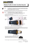
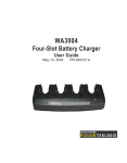
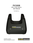
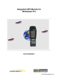
WORKABOUT PRO RFID READER WA9900-G2 INSTRUCTIONS
1. Preparation
This RFID reader installation instruction sheet applies to the following WORKABOUT PRO
model numbers: 7525C and 7527S.
Note:
Warning:
The installation of this RFID PCMCIA Card must be performed using the appropriate antistatic devices. If such devices are unavailable, discharge static from your body by touching a
grounded metallic object before opening any covers on the unit.
Important:
The WORKABOUT PRO does not support hot-swapping of PCMCIA Cards. All power
sources must be switched off before a card is inserted in the unit.
The RFID Reader kit consists of a PCMCIA Card, an antenna cable, an antenna mounted in an end-cap, plus a
mechanical stop to secure the card inside the unit.
End-Cap Containing Antenna
Mechanical Stop
RFID Decoder Card
Screws For Mechanical Stop
Figure 1 Contents Of The Kit
The PCMCIA Card slides into the PCMCIA slot in your WORKABOUT PRO. It can be used alongside the built-in
Bluetooth radio. The end-cap replaces the existing end-cap on your WORKABOUT PRO.
For detailed information on operation and specifications, please refer to the WORKABOUT PRO Hand-Held
Computer User Manual for your unit.
2. Installation
To install the RFID Reader:
Important:
Back up any data in RAM first, since it will be erased when the unit is turned off.
1.
If your WORKABOUT PRO is using AC power, disconnect it.
2.
Remove the WORKABOUT PRO battery pack.
3.
Slide the hardware power switch inside the battery compartment to switch off internal battery-backup
power:
OFF
OFF
On The C Version
On The S Version
Figure 2 Switching Internal Battery-Backup Power Off
4.
Remove the end-cap at the top of the WORKABOUT PRO. Use a #1 Phillips screwdriver on the four
screws.
April 15, 2008
8100171 Rev. A
Sheet 1 of 3
5.
Install the Psion Teklogix PCMCIA Expansion Module kit, model WA9101-G1 (not included) in the
WORKABOUT PRO. This provides the connector for the PCMCIA Card.
Installed PCMCIA Expansion Module
Backplate Removed To Show PCMCIA Connector
Figure 3 The WORKABOUT PRO With The PCMCIA Expansion Module Installed
6.
Slide the PCMCIA Card, with the label facing up, into the PCMCIA slot until it is fully seated:
Radio Card
Figure 4 Inserting The Radio Card
7.
Connect the antenna cable to the connector on the right of the RFID card:
Antenna Cable
Antenna Connector
Radio Card
Figure 5 Connecting The Antenna
8.
Insert the mechanical stop so that the antenna cable protrudes through the gap:
Mechanical Stop
Antenna Connector
Screws (4 places)
Antenna Cable
Figure 6 Attaching The Mechanical Stop
9.
Tighten the 4 screws of the mechanical stop to a torque of 2 lb-in (0.23 N·m).
Use a #1 Phillips screwdriver.
April 15, 2008
8100171 Rev. A
Sheet 2 of 3
10. Attach the end-cap.
End-Cap
Figure 7 Attaching The End-Cap
11. Tighten the 4 end-cap screws to a torque of 3 lb-in (0.34 N·m).
12. Slide the hardware power switch to turn battery-backup power back on.
ON
ON
On The C Version
On The S Version
Figure 8 Switching Internal Battery-Backup Power On
13. Replace the battery and battery cover.
14. Verify the installation.
April 15, 2008
8100171 Rev. A
Sheet 3 of 3
COMPANY HEADQUARTERS AND CANADIAN SERVICE CENTRE
Psion Teklogix Inc.
2100 Meadowvale Boulevard, Mississauga
Ontario, Canada L5N 7J9
Tel:+1 905 813 9900
Fax:+1 905 812 6300
E-mail:salescdn@psion.com