1
KVM.net ® II
User Guide
w w w . m i n i c o m . c o m
International HQ
North American HQ
European HQ
Jerusalem, Israel
Linden, NJ, USA
Dübendorf, Switzerland
Tel: + 972 2 535 9666
minicom@minicom.com
Tel: + 1 908 486 2100
info.usa@minicom.com
Tel: + 41 44 823 8000
info.europe@minicom.com
Technical support - support@minicom.com
5UM70156 V2 8/08
USER GUIDE
About this User Guide
This User Guide provides installation and operation instructions for the KVM.net II
Manager system produced by Minicom Advanced Systems. It is intended for
system administrators and network managers, and assumes that readers have
general understanding of networks, LDAP, hardware and software.
All information in this User Guide is subject to change without prior notice.
User Guide Feedback
Your feedback is very important to help us improve our documentation. Please
email any comments to: ug.comments@minicom.com
Please include the following information: Guide name, part number and version
number (as appears on the front cover).
Copyright
Copyright © 2008 Minicom Advanced Systems Ltd.
All marks are trademarks or registered trademarks of their respective owners.
1
KVM.NET ® II
Table of Contents
1. Introduction..................................................................................................... 6
1.1 Key features .......................................................................................................... 6
1.2 System components ............................................................................................. 7
1.3 System diagram .................................................................................................... 7
1.4 Terminology .......................................................................................................... 8
2. Pre-installation guidelines.............................................................................. 9
2.1 Access services details ...................................................................................... 10
2.1.1 Adding user defined Access services.............................................................. 10
3. Understanding the system – an overview.................................................... 11
3.1 Creating users..................................................................................................... 11
3.2 Forming users into Groups................................................................................. 12
3.3 Creating Targets ................................................................................................. 12
3.4 Forming Targets into sets................................................................................... 13
3.5 Associating a User Group with a Target Set ...................................................... 13
3.6 Access services .................................................................................................. 14
4. Setting up the system ................................................................................... 16
4.1 Connecting the KVM.net II Manager ................................................................... 16
4.2 KVM.net II Manager’s default IP address............................................................ 17
4.2.1 Changing the KVM.net II Manager Network parameters .................................. 17
5. Displaying the KVM.net II web interface ...................................................... 18
5.1 Menu section....................................................................................................... 19
6. Creating users............................................................................................... 21
6.1 General tab.......................................................................................................... 22
6.2 User Group tab.................................................................................................... 22
6.2.1 Removing Users from a Group ....................................................................... 23
6.3 Access Permissions tab ..................................................................................... 23
6.4 Saving a user ...................................................................................................... 24
6.4.1 Deleting a user............................................................................................... 25
6.5 Creating a User Group ........................................................................................ 25
6.5.1 Access Permissions tab ................................................................................. 27
6.5.2 Allowed Services tab...................................................................................... 28
6.5.3 Saving the new Group.................................................................................... 28
6.5.4 Deleting a User Group.................................................................................... 29
7. Configuring Targets...................................................................................... 30
7.1 Access Services tab............................................................................................ 31
7.1.1 Default access service ................................................................................... 32
2
USER GUIDE
7.1.2 Minicom KVM/IP ............................................................................................ 32
7.2 Target Sets tab.................................................................................................... 33
7.3 Access Permissions tab ..................................................................................... 34
7.4 Saving the Target................................................................................................ 35
7.5 Deleting Targets.................................................................................................. 35
7.6 Creating a Target Set .......................................................................................... 35
7.6.1 Access Permissions tab ................................................................................. 36
7.6.2 Saving the Target set ..................................................................................... 36
7.6.3 Deleting a Target Set ..................................................................................... 37
8. Management / Devices.................................................................................. 38
8.1 Setting each IP device to be KVM.net enabled................................................... 39
8.2 Configuring the IP devices in the KVM.net II ...................................................... 39
8.2.1 The Advanced button ..................................................................................... 40
8.2.2 Performance .................................................................................................. 40
8.2.3 Mouse ........................................................................................................... 41
8.3 KVM Ports tab ..................................................................................................... 42
8.3.1 DXU IP II units ............................................................................................... 42
8.4 Targets ................................................................................................................ 43
8.5 Network tab......................................................................................................... 44
8.5.1 Serial tab ....................................................................................................... 45
8.6 Saving the IP device configuration changes ...................................................... 45
8.7 Deleting IP devices ............................................................................................. 46
8.8 Device discovery................................................................................................. 46
9. Settings - Applications ................................................................................. 46
9.1 Access services .................................................................................................. 47
9.1.1 Minicom KVM/IP ............................................................................................ 48
9.2 KVM switches...................................................................................................... 49
9.2.1 Uploading a new KVM Switch......................................................................... 50
9.3 Account Policy.................................................................................................... 50
9.3.1 Password policy............................................................................................. 51
9.3.2 External authentication (LDAP)....................................................................... 52
9.4 Global Settings ................................................................................................... 57
9.4.1 KVM.net II / KVM/IP Session Idle timeout........................................................ 58
10. Configuring Access Services – introduction ............................................. 60
10.1 Access Services default values ........................................................................ 60
10.1.1 General note about application paths............................................................ 60
10.1.2 Minicom PX Serial........................................................................................ 61
10.1.3 Web............................................................................................................. 62
10.1.4 ILO .............................................................................................................. 62
10.1.5 RDP ............................................................................................................ 64
3
KVM.NET ® II
10.1.6 SSH............................................................................................................. 65
10.1.7 VNC ............................................................................................................ 66
10.1.8 Telnet .......................................................................................................... 68
10.1.9 VMware Server ............................................................................................ 69
10.1.10 New Access Services ................................................................................. 70
11. Configuring Access services for individual Targets ................................. 72
11.1 Default access service ...................................................................................... 72
11.2 Minicom PX Serial ............................................................................................. 72
11.2.1 Web............................................................................................................. 73
11.2.2 ILO .............................................................................................................. 74
11.2.3 RDP ............................................................................................................ 75
11.2.4 SSH............................................................................................................. 77
11.2.5 VNC ............................................................................................................ 78
11.2.6 Telnet .......................................................................................................... 80
11.2.7 VMware Server ............................................................................................ 81
12. Accessing Targets - Administrator ............................................................ 83
12.1 Access page columns....................................................................................... 83
12.1.1 Power management column ......................................................................... 83
12.1.2 Name column............................................................................................... 83
12.1.3 Status column .............................................................................................. 83
12.1.4 More access services column ....................................................................... 84
12.2 Accessing a Target via KVM/IP remote session............................................... 84
12.2.1 Taking over a busy remote session............................................................... 85
12.2.2 The Toolbar ................................................................................................. 85
12.2.3 Switching to a different server....................................................................... 86
12.2.4 Changing the performance settings............................................................... 86
12.2.5 Adjusting the Video settings.......................................................................... 87
12.2.6 Keyboard key sequences ............................................................................. 89
12.2.7 Synchronizing mouse pointers ...................................................................... 90
12.2.8 Minicom icon menu features ......................................................................... 94
12.2.9 Full screen mode.......................................................................................... 98
12.2.10 Disconnecting the remote session............................................................... 98
12.3 Accessing a Target through other Access Services ........................................ 98
12.4 Exiting the KVM.net II system ........................................................................... 99
13. Accessing the system as a User .............................................................. 100
13.1 Power column ................................................................................................. 100
13.2 Status column ................................................................................................. 100
13.3 Connecting to a Target ................................................................................... 101
13.3.1 Connecting to a KVM/IP device Target........................................................ 101
13.3.2 Connecting to a non-KVM/IP device Target................................................. 101
4
USER GUIDE
13.3.3 Changing the password.............................................................................. 102
14. Accessing an IP device directly ............................................................... 103
15. Maintenance of the system....................................................................... 104
15.1 Backup & Restore ........................................................................................... 104
15.1.1 The backup elements ................................................................................. 104
15.1.2 Restoring database backup ........................................................................ 105
15.2 Restore Settings.............................................................................................. 106
15.2.1 Restoring KVM.net II to factory default settings ........................................... 106
15.2.2 Resetting KVM.net II configuration.............................................................. 106
15.3 Firmware upgrade ........................................................................................... 107
15.3.1 Upgrading the IP devices firmware.............................................................. 107
15.4 Replication ...................................................................................................... 108
15.4.1 Connecting the secondary unit to the network ............................................. 108
15.4.2 Configuring the secondary unit ................................................................... 108
15.4.3 Configuring the primary unit........................................................................ 109
15.4.4 Promoting a secondary unit to a standalone unit ......................................... 109
15.4.5 Reconfiguring the primary and secondary units ........................................... 110
15.4.6 Primary unit and secondary unit troubleshooting ......................................... 111
15.4.7 Checking the secondary unit....................................................................... 111
15.4.8 Redoing the secondary and primary unit configuration................................. 111
15.5 Event log ......................................................................................................... 112
15.5.1 Drop-down search menus........................................................................... 112
15.5.2 Access, System or Configuration tabs......................................................... 113
15.5.3 Advanced button ........................................................................................ 113
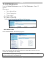
16. Unit Maintenance ...................................................................................... 114
16.1 Date & Time tab............................................................................................... 114
16.2 Network tab ..................................................................................................... 114
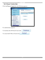
16.3 Power Control tab ........................................................................................... 115
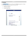
17. About ......................................................................................................... 116
18. General troubleshooting........................................................................... 117
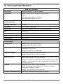
19. Technical Specifications........................................................................... 120
19.1 WEEE compliance........................................................................................... 121
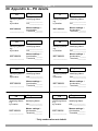
20. Appendix A – PX details ........................................................................... 122
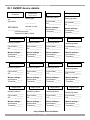
20.1 KVM/IP device details...................................................................................... 123
5
KVM.NET ® II
1. Introduction
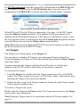
KVM.net II is a robust central management appliance that provides reliable and
secure management of KVM IP devices.
KVM.net II integrates with Minicom IP devices and Serial console server devices
to facilitate an intuitively manageable, centralized out-of-band access portal designed to maintain all IT assets. KVM.net II centralizes all user account
information relevant for IP device administration without interfering in the standalone survivability of each device.
KVM.net II is Web based, and is managed using XML over HTTPS, which allows
for secure, yet highly adaptable administration.
Designed to work across LAN or WAN, KVM.net II, monitors and auto configures
KVM IP devices whether residing on the local enterprise network or in remote
branches.
KVM.net II delivers the most advanced solution for enterprise IT management and
remote control. It supports hundreds of servers in an environment that is
completely configurable by the network administrator.
1.1 Key features
IT Management - KVM.net II centralizes the management of all devices,
authentication and global operation from a Web browser. The local administrator
can monitor, control and manage the various devices, user accounts and
authorization from one Web interface.
Automatic Discovery - Minicom IP devices are discovered automatically by the
KVM.net II Manager.
Access Services - Connect to a variety of both hardware and software external
resources such as: ILO, RDP, SSH, VNC and web pages etc, from the KVM.net II
interface.
Security - KVM.net II provides an extra security layer in addition to the existing
authentication and encryption policy – ensuring that only authorized users can
access servers.
Availability - Maximizes uptime by centralizing management and allowing
immediate and effective maintenance.
6
USER GUIDE
Virtual Media - Virtual Media is a very useful tool for those who need to manage
large numbers of computers such as commercial IT data center managers. A Target
computer can be made to boot to one of many virtual disks that can perform any
variety of tasks such as virus scans of the Target’s physical drive or patch
management or even complete installation of the operating system on a Target
computer.
1.2 System components
The KVM.net II Manager system comes with the following:
•
KVM.net II Manager appliance
•
Rack mounting kit
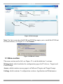
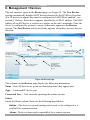
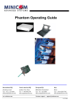
1.3 System diagram
The diagram below gives a brief outline of the KVM.net II system setup. Section 3
on page 11 explains the system setup in more detail.
7
KVM.NET ® II
Remote location
Remote user
Smart IP Access
MINIC OM
Powe r
SMARTIPACCESS
Re mo te
Loc al
Res et
Internet / VPN / MAN
Remote user
Target servers
KVM.net II Manager
Firewall
UID
1
HP
Pr oLiant
DL140
2
KVM. net
Pow erEdge
1 9 5 0
G2
LAN
Smart IP Access
www.minicom.c
om
PDU
1
1
2
2
L
A
N
POWER
100-240 VAC 50/60 Hz
S
E
R
I
A
L
CONSOLE
COMPUTER
Smart CAT5 Switch 16 port
Printer
9
10
11
1
2
3
12
13
14
15
4
5
6
7
COMPUTER
POWER
100-250
VAC 50/6 0 Hz
PX 1 to 1
connection to
Servers
PX’s
Targets
Figure 1 System diagram
1.4 Terminology
Below are some terms and their meanings used in this guide.
Term
Meaning
Targets
Computers/servers and other services e.g. printers, firewalls, PDUs etc. that
are accessed remotely via the KVM.net II.
The PC running a remote KVM.net II session
The process of accessing and controlling Targets connected to a KVM/IP
device from a Client computer
Client computer
Remote session
8
USER GUIDE
2. Pre-installation guidelines
Prepare a list of all KVM.net II system components. You will need this information
to configure the system.
Appendix A on page 122 contains 2 lists of the details you need to prepare for
Minicom KVM/IP devices and PX units (not PX Serial). Photocopy or print out
Appendix A. For other access services see section 2.1 below.
The lists should include the IP device name and MAC address, KVM switch and
the Target details.
For each Target, list:
•
A unique and clearly identifiable name
•
The operating system
•
Non-default mouse settings. Default mouse settings do not need to be
listed
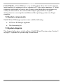
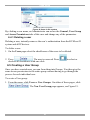
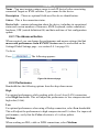
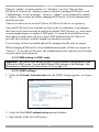
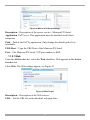
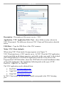
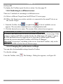
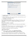
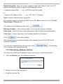
Note! For Windows XP, 2003 Server, Vista and 2008 Server
(Relevant to all IP devices except PX USB)
For Windows XP, 2003 Server, Vista and 2008 Server deactivate Enhanced
pointer precision. To do so:
From the Control Panel select Printers and Other Hardware. Click the Mouse
icon. The Mouse Properties box appears. See Figure 2. Select the Pointer Options
tab.
Figure 2 Pointer tab
The Motion section slider bar must be in the center, and the Enhanced pointer
precision checkbox must be unchecked. Click OK to save changes.
9
KVM.NET ® II
2.1 Access services details
Besides the Minicom KVM/IP devices mentioned above, you can connect to
Targets via the following Access services through KVM.net II:
•
Minicom’s PX Serial
•
Web
•
ILO
•
RDP
•
SSH
•
VNC
•
Telnet
•
VMware Server
These services are elaborated on in the section 3.6.
All service applications must be installed on the local (client) computers.
See section 10 on page 60 which sets out the details required for each of the above
Access service.
2.1.1 Adding user defined Access services
You can also add your own access services, explained on page 70.
10
USER GUIDE
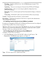
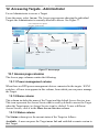
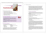
3. Understanding the system – an overview
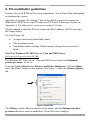
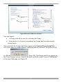
The figure below shows a typical KVM.net II application.
Figure 3 KVM.net II typical application
The system works as follows:
Data centers in locations throughout the world are connected to Minicom IP
devices and to other 3rd party access services. The Minicom IP devices are
KVM.net enabled allowing KVM.net II to access/control the Targets connected to
all IP devices via IP.
Users access the KVM.net II web interface and depending on their level of access
permissions can access and control the Targets.
3.1 Creating users
An Administrator can create users with 2 different possible permission types:
•
Administrator
•
User
11
KVM.NET ® II
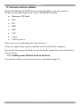
A User can be a full User or just View only. These permission types are explained
fully in section 9.3. In the example below 4 users are created with various
permission types.
User
Administrator View Only
Phil
Sam
Dave
User
Jon
Figure 4 Users with different permissions
Once an Administrator creates Targets or sets of Targets (explained below) in the
system, users can be assigned access to individual Targets or sets of Targets.
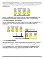
3.2 Forming users into Groups
You can form users into Groups. In the example below 3 users are formed into the
Finance group. Note! Groups can contain users with different levels of user
permissions.
User
Phil
Administrator View Only
Sam
Dave
User
Finance Group
Jon
Administrator View Only
Sam
Dave
User
Jon
Figure 5 Forming users into groups
3.3 Creating Targets
An Administrator creates Targets corresponding to the physical servers connected
to the IP devices, explained in section 7, and also to Targets corresponding to e.g.
printers, firewalls, PDUs and IDSs etc accessed via Access Services™ - see page
14. In the example below, four Targets are created and given identifying names.
They can be named by location, server type or operating system or any other
unique feature associated with that particular server.
12
USER GUIDE
Target servers
Dell
#1
Dell
#2
Dell
#3
Dell
#4
Figure 6 Created Targets
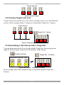
3.4 Forming Targets into sets
Targets can be formed into sets. You can for example create a set of all financial
servers. In the example below 3 Targets are formed into Target Set - Finance.
Target servers
Dell
#1
Dell
#2
Dell
#3
Dell
#4
Target Set - Finance
Dell
#1
Dell
#2
Dell
#3
Figure 7 Forming Targets into sets
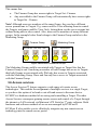
3.5 Associating a User Group with a Target Set
You can then associate the User Group with the Target Set, thus giving access
rights to all the Targets in the Set to all members of the Group.
Finance Group
Administrator View Only
Sam
Dave
Target Set - Finance
User
Dell
#1
Jon
Dell
#2
Dell
#3
Figure 8 User Group - Target Set association
In the example above the Finance Group is associated with the Target Set –
Finance.
13
KVM.NET ® II
This means that:
•
The Finance Group has access rights to Target Set - Finance.
•
Any user added to the Finance Group will automatically have access rights
to Target Set - Finance.
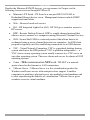
Note! Although users are members of the same Group, they can have different
access permissions to Targets. E.g. some could be Users allowing them to control
the Targets, and some could be View Only, letting them see the server screens but
without being able to take control. Also, users can be members of many different
groups. In the example below Sam belongs to the Finance Group and also to the
Marketing Group.
Finance Group
Marketing Group
Administrator View
ViewOnly
Only User
Sam
Dave
Jon
User
Administrator
Phil
Sam
Figure 9 Same user in different Groups
The Marketing Group could be associated with Targets or Target Sets that the
Finance Group is not. Sam being a member of both Groups has access to Targets
that both Groups are associated with. Phil only has access to Targets associated
with the Marketing Group. Dave and Jon only have access to Targets associated
with the Finance Group.
3.6 Access services
The Access Services™ feature supports a wide range of remote access
technologies. This enables the assignment of multiple services to a single Target,
so you have the option of in-band or out-of-band access to the same device.
KVM/IP is a hardware method of accessing and controlling a Target. The other
Access Services encompass gaining remote access and control of a Target through
the internet or LAN network via Minicom’s PX Serial or 3rd party software. Both
hardware and software methods of access are managed by KVM.net II.
KVM.net II also enables you to effortlessly integrate any new remote access
technology into the remote access portal.
14
USER GUIDE
Besides the Minicom KVM/IP devices, you can connect to Targets via the
following Access services through KVM.net II:
•
•
Minicom’s PX Serial - PX Serial is a one-port RS232/422/485 to
Redundant Ethernet device server. Management features include SNMP
support and email alerts.
Web – Browser based web service
•
ILO - HP Integrated Lights-Out (iLO). HP ILO gives seamless access to
HP servers.
•
RDP - Remote Desktop Protocol. RDP is a multi-channel protocol that
allows a user to connect to a computer running Microsoft Terminal Services.
•
SSH - Secure Shell. SSH is a network protocol that allows data to be
exchanged using a secure channel between two computers. An SSH client
program is typically used for establishing connections to an SSH daemon.
•
VNC - Virtual Network Computing. VNC is a graphical desktop sharing
system which uses the RFB protocol. VNC is platform-independent — a
VNC viewer on any operating system usually connects to a VNC server on
any other operating system. There are clients and servers for almost all GUI
operating systems.
•
Telnet - TELecommunication NETwork. TELNET is a network
protocol used on the Internet or LAN connections.
•
VMware Server - VMware Server is a free virtualization product for
Windows and Linux servers with enterprise-class support. It enables
companies to partition a physical server into multiple virtual machines and
to start experiencing the benefits of virtualization. VMware Server gives
seamless access to virtual machines.
15
KVM.NET ® II
4. Setting up the system
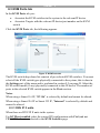
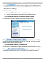
Set up the Minicom IP device systems according to their User Guide instructions.
In order to be managed by KVM.net II, all Minicom IP devices must be configured
to be KVM.net enabled. This is done from the Network Configuration page of each
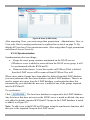
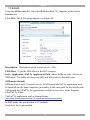
IP device. For example, see the KVM.net section in Figure 10, KVM.net is enabled
by selecting the Enable KVM.net checkbox.
Figure 10 Network Configuration page sample
Also in the KVM.net section in Figure 10, specify how the KVM.net II server
detects the IP device. This can be done either by:
Manager Auto Discovery – when checked, KVM.net II automatically detects the
IP device if it resides on the same network segment.
Manager IP – If the IP device resides on a different segment, type the static IP
address of the KVM.net II Manager. (We advise typing the static IP address of the
KVM.net II Manager even if the IP device resides on the same network segment as
the KVM.net II Manager).
Install 3rd party access services according to their own installation and
configuration instructions. See section 10 on page 60 for details required for the
integration of the Access services into the KVM.net II system.
4.1 Connecting the KVM.net II Manager
1. Connect the KVM.net II Manager to the network as follows: On the rear panel
connect an Ethernet cable to LAN 1. Connect the other end of the Ethernet
cable to the network switch.
2. Connect the KVM.net II Manager to a power supply outlet.
16
USER GUIDE
4.2 KVM.net II Manager’s default IP address
Each KVM.net II Manager unit comes with the following default values:
IP address - 192.168.1.250.
Subnet mask - 255.255.255.0
Gateway - 192.168.1.1
If these values are not suitable for your network, follow the steps in the section
below to display the KVM.net II interface. You can then change the IP address of
the KVM.net II Manager in the Network tab under Settings/Unit Maintenance,
see section 16.2 on page 114.
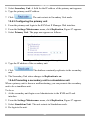
4.2.1 Changing the KVM.net II Manager Network parameters
1. Open your Web browser (Internet Explorer version 6.0 or higher).
2. Type in the IP address of the KVM.net II Manager (default IP address
https://192.168.1.250) and press Enter. (Change your computer network
settings, if necessary). The Login page appears.
3. Type the login name admin and password access.
4. Navigate to the Network tab under Settings/Unit Maintenance and change the
network parameters to suit your network configuration.
5. Press Save and restart the KVM.net II Manager.
6. Wait for the system to restart and login with the new IP address.
17
KVM.NET ® II
5. Displaying the KVM.net II web interface
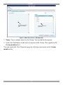
To display the Web interface:
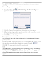
1. Open your Web browser (Internet Explorer version 6.0 or higher).
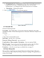
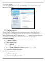
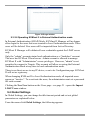
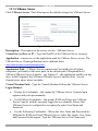
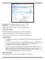
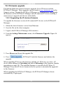
Windows Vista Note! To login to the Web configuration interface with Windows
Vista, run Internet Explorer as Administrator. To do this, right-click the Internet
Explorer icon and select Run as administrator. See figure below.
Figure 11 Select Run as administrator
2. Type in the IP address of the KVM.net II Manager (default IP address
https://192.168.1.250) and press Enter. Note! The IP address must begin with
https:// and not http://. The Login page appears. Bookmark it for easy reference.
3. Type the login name and password. Default username is admin and password is
access.
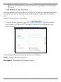
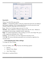
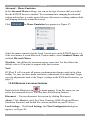
4. Press Enter. The Web interface appears, see Figure 12.
18
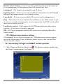
USER GUIDE
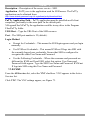
New devices identified
with their MAC address
Menu section
IP device type
Once devices are
identified by a
name they appear
here
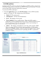
Figure 12 Devices page
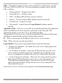
Note! On first connection the KVM.net II GUI prompts you to install the KVM.net
II client software, see Figure 13. Click Install.
Figure 13 KVM.net II client
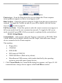
5.1 Menu section
The menu section on the left, see Figure 12 is sub-divided into 3 sections:
Management, which includes the configuration pages for IP devices, Targets and
Users/Groups.
Access, which contains access pages to all allowed Targets and Target Groups.
Settings which contains 2 configuration sections: Application and Maintenance.
19
KVM.NET ® II
This Guide explains the menu sections from the point of view of first setting up the
system and then operating it.
So the guide explains in the following order how to:
•
Create Users
•
Configure Targets
•
Configure Devices
•
Configure Settings
•
Configure Access Services
•
Access the system
•
Configure Advanced settings
20
USER GUIDE
6. Creating users
There are two possible methods of inputting users into the system. When using
local authentication (see page 50) users and groups are created in the KVM.net II
GUI. When using an LDAP authentication server (see page 52) users and groups
are imported from a Windows Active Directory. With both authentication methods,
an Administrator can grant users different access permissions as follows:
Administrator - An Administrator can view, modify, manage and control all
KVM.net II Manager configuration settings, including creating new users.
User – A User cannot access or change any of the KVM.net II Manager
configuration settings. When a User logs in, only the Targets that the user has
permission to access appear. View Only – This user can only view permitted
Target screens without keyboard and mouse control. A “view only” indicator
appears on the viewer’s local mouse pointer. View only has no effect on Access
services.
With local authentication, once you have created users you can form them into
Groups, making management changes easier by e.g. adding or deleting permitted
Targets per Group rather than per individual user. Creating Groups is explained in
section 6.5 on page 25.
In LDAP mode go to section 6.1 below.
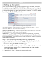
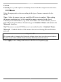
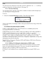
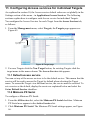
To create a new user (in local authentication mode):
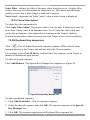
1. From the Management menu, select Users. The Users page appears showing
the default Administrator (admin) at the top of the list, see Figure 14.
Click a name to edit
User properties
Figure 14 Users page
The columns show the following:
•
•
Name – User’s login name. You can search for a user by typing the login
name in the Search a user field and clicking . You can sort the names out
in alphabetical order A-Z or Z-A by clicking the top of the Name column.
Member of – groups the user is a member of.
21
KVM.NET ® II
•
•
Permission Level – Administrator or User. You can sort the users out in
Permission Level order - Administrators then Users or Users then
Administrators - by clicking the top of the Permission Level column.
Description – Optional description.
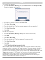
2. Click
. The following appears.
Figure 15 New User
6.1 General tab
Fill in the following details:
User name - type a login name. A User name cannot be identical to any other
existing User name. It can contain uppercase or lowercase characters except for the
following:
: ; ? & < > ”
A User name cannot include spaces.
Full Name - type the User’s real name
Password / Retype Password - type a password.
E-mail address, Phone number, Description – these are optional fields.
Block Account - To prevent a user from entering the system, select the Block
Account checkbox. To re-enable the account, unselect the checkbox.
Permission – select the account type as outlined above on page 21.
6.2 User Group tab
Once you have created users you can put them into existing Groups. This gives
users the access rights of that User Group. Section 6.5 on page 25 explains how to
create a User Group.
22
USER GUIDE
To add a User to an existing User Group or Groups:
1. Press the Users Group tab, Figure 16 appears. All existing Groups appear in
the All User Groups list.
Once selected, User
Groups appear here
All User Groups in the
system appear here
Figure 16 User Group tab
2. Select the Groups that the new User will be a member of. The Groups appear in
the Member of list.
6.2.1 Removing Users from a Group
To remove Users from a Group:
In the All User Groups section, unselect the Group’s checkbox. The Group is
removed from the Member of list.
6.3 Access Permissions tab
You can choose which Targets and Target sets the user has permission to access.
Notes:
•
A User can have access to a Target as an individual User or as a Group
member.
•
A User or Group of Users can be associated with several Target Sets.
•
When a User logs into the KVM.net II web interface he sees only Targets
and Target Sets that he has been associated with. See section 13 on page
100.
23
KVM.NET ® II
To choose which Targets / Target Sets the user will have access to:
1. Press the Access Permissions tab. The following appears.
Targets and Target Sets
that the new user has
permission to access
appear here
Select from the All
Targets and All Target
Sets lists those which
the new user will have
permission to access
Figure 17 Access Permissions tab
The All Targets and All Target Sets lists show the Targets and All Target sets in
the system.
2. Select the checkboxes of the desired Targets / Target sets. They appear in the
Targets and Target Sets: list.
To disassociate a User/Group from a Target:
Unselect the Targets / Target Sets checkbox from the relevant list.
6.4 Saving a user
Click
. The user’s details are now in the system.
Repeat this process to add more users. When finished, click
. All
users appear on the Users page. The number of users appears in brackets after
Users in the menu, see Figure 18. User Groups appear as a sub-folder in the menu.
Creating user groups is explained below.
24
USER GUIDE
Number of users in the system
Figure 18 Users in the system
By clicking a user name, an Administrator can access the General, User Group
and Access Permissions tabs of this user and change any of the parameters.
6.4.1 Deleting a user
Deleting a user, instantly removes the user’s authorization from the KVM.net II
system and all IP devices.
To delete a user:
1. On the Users page select the checkboxes of the users to be deleted.
. The user is removed. Press
2. Press
deselect all checkboxes with one click.
to select or
6.5 Creating a User Group
Once you have created users you can form them into Groups. You then give the
same access permissions to the entire group without having to go through the
process for each individual user.
To create a User group:
1. From the menu, click Users or User Groups. On either of these pages, click
. The New User Group page appears, see Figure 19.
25
KVM.NET ® II
Users that are members
of this Group appear
here
All users in the system
appear here
Figure 19 New User Group - Members tab
2. Name: Type a unique name for the Group. You can add a description.
3. Select the checkboxes of the users to be part of the Group. They appear in the
Group members list.
You can access the User Properties page by clicking a user name in the Group
members list.
26
USER GUIDE
6.5.1 Access Permissions tab
Click the Access Permissions tab, Figure 20 appears.
Targets and Target Sets
that the new Group has
permission to access
appear here
Select from the All
Targets and All Target
Sets lists those which
the new Group will have
permission to access
Figure 20 Access Permissions tab
From the All Targets and All Target Sets lists select the checkboxes of those
which the new User Group will have permission to access. When selected the
Target/Set appears in the Targets and Target Sets list.
To remove Targets/Sets, unselect the checkboxes.
27
KVM.NET ® II
6.5.2 Allowed Services tab
Click the Allowed Services tab. The following appears.
Figure 21 Allowed Services tab
Here you assign Access Services to Group members. If a Group member has
permission to access a Target, but there are no assigned Access Services for the
Group, then the Group member will not be able to access the Target.
Select the checkboxes of all access services allowed to this Group.
6.5.3 Saving the new Group
Click
. The Group’s details are now in the system.
Repeat this process to add more Groups. When finished, click
All Groups appear on the User Groups page, see Figure 22.
.
Tip! The allowed services appear as icons. To see which service the icon
represents, hold the mouse over the icon and a tooltip appears with the name of the
service.
You can create different access profiles. You can give permission to Targets and
define different access rights through the Allowed Services.
28
USER GUIDE
Icons of access services
allowed appear here
User Groups
Figure 22 User Groups page
6.5.4 Deleting a User Group
To delete a Group:
1. On the Users Group page select the checkboxes of the Groups to be deleted.
2. Press
. The Groups are removed. Press
deselect all checkboxes with one click.
Note: Deleting a Group will not delete the individual users.
29
to select or
KVM.NET ® II
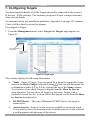
7. Configuring Targets
You must input the details of all the Targets physically connected to the system’s
IP devices / KVM switches. This includes giving each Target a unique name and
other relevant details.
As mentioned in the pre-installation guidelines, Appendix A on page 122 contains
2 lists of all the details you need to prepare.
To configure a Target:
1. From the Management menu, select Targets the Targets page appears see
Figure 23.
Click here to display the
Targets page
Total number of
Targets in the
system
Click a name to edit
Target properties
Figure 23 Target page
The columns display the following information:
•
Name – Name of Target. You can search for a Target by typing the Target
name in the Find a Target field and clicking . You can sort the names out
in alphabetical order A-Z or Z-A by clicking the top of the Name column.
You can also select which Targets to display from the Show by Service
drop-down list. You can show all Targets or just show Targets with a
particular Access Service, to do so choose the desired service from the Show
by Service drop-down list.
•
KVM/IP Device – The type of Minicom KVM/IP device, the target is
connected to.
•
Access Services - Icons of Access services available to access the target.
To see which service the icon represents, hold the mouse over the icon and
a tooltip appears with the name of the service.
30
USER GUIDE
•
Target Sets – The Target Sets this Target is a member of.
•
Description - optional description of the Target.
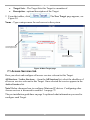
2. From the toolbar, click
Figure 24.
. The New Target page appears, see
Name - Type a unique name for each server in the system.
Once selected access
services appear here
All possible access
services appear here
Figure 24 New Target page
7.1 Access Services tab
Here you select and configure all access services relevant to this Target.
All Services / Active Services: – from the All Services list, select the checkbox of
all access services relevant to this Target. Once selected the service appears in the
Active Services list.
Note! Below discusses how to configure Minicom IP devices. Configuring other
Access services is discussed in section 11 on page 72.
The pre-installation guidelines on page 9 explained what information you need to
configure each Target.
31
KVM.NET ® II
7.1.1 Default access service
You can set any of the access services to be the default service. This means that the
service will be used to access the Target by default when selecting the Target by
clicking the Target name. To access the Target via a different service, the service
must be selected. To set a service as the default, display the service as explained
below and select the Set as Default Service checkbox – circled in Figure 24.
7.1.2 Minicom KVM/IP
KVM/IP Device / Port number: Assign the IP device and KVM switch port
number (where relevant) to which this Target is physically connected.
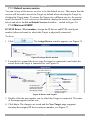
To do so:
1. Click
. The Assign Device window appears, see Figure 25.
List of device types in
the system
Figure 25 Assign Device window
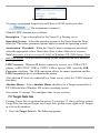
2. From the list, expand the device type the target is connected to and select the
actual device the target is connected to, see Figure 26.
A tick means there is an
assigned Target to this
port
Target name as
configured by
Administrator
Actual IP device the
Target is connected to
List showing port
numbers of KVM switch
attached to IP device
with assigned Targets.
A blank space means
there is no currently
assigned Target
Figure 26 Device and Targets
3. Double-click the port number row to which the Target is connected. The name
of the target appears in that row.
4. Click Save. The changes are saved and the New Target page reappears
showing the assigned IP device and port number, see Figure 27.
32
USER GUIDE
Figure 27 KVM/IP Device / Port number
To remove an assigned Target from an IP device/ KVM switch port click
. The assignment is removed.
Other KVM/IP elements are as follows:
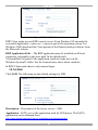
Description – Type a description for the Target. E.g. Backup server.
Operating System – Select the operating system of the Target from the Dropdown list. The mouse parameter options adjust to match the operating system.
Acceleration / Threshold – When the Target’s mouse settings are not default
select the appropriate values. Match the values to that of the server’s mouse.
Note! (Relevant to all IP devices except PX USB) For Windows XP, 2003 Server, Vista
and 2008 Server. Go to the Mouse settings on the Target and uncheck Enhance
pointer precision.
USB Converter - When an IP device connects to a server via a USB to PS/2
adapter, or ROC/RICC USB, or X RICC USB or Specter USB, select the USB
Converter checkbox. The USB conversion affects the mouse emulation and the
USB Converter helps to synchronize the mouse.
Also when an IP device is connected to a Linux server, select the “USB Converter”
checkbox.
Absolute Mouse – Select Absolute Mouse checkbox for a Target connected to a
PX USB which has Windows ME or later operating system.
See section 11 on page 72 to configure other Access services.
7.2 Target Sets tab
Creating Target Sets is explained in section 7.6 on page 35. Once you have created
Target Sets you can put Targets into Target Sets, giving access rights to all Targets
in a Set to all members.
1. Press the Target Sets tab. The following appears.
33
KVM.NET ® II
Target sets that this
Target is a member of
appear here
All Target sets created
in the system appear
here
Figure 28 Target Sets
2. From the All Target Sets list, select the checkboxes of the Target Sets you want
the Target to be associated with. The Target Set appears in the Is a Member of
list.
7.3 Access Permissions tab
You can choose which Users and Groups can have access permission to the Target.
Press the Access Permissions tab. The following appears.
Users and Groups that
have permission to
access this Target
appear here
Select from the All Users
and All Groups lists
those which will have
permission to access
this Target
Figure 29 Access Permissions tab
All existing Users appear in the All Users list. All Groups appear in the All
Groups list.
To choose which Users / Groups have access to the Target:
1. Select the checkboxes of the Users or Groups. They appear in the Users and
Groups: list.
To disassociate a User/Group from a Target:
34
USER GUIDE
Unselect the User/Group checkbox from the relevant list.
7.4 Saving the Target
Click
. The Target details are now in the system.
Repeat this process to input all connected servers. When finished, click
. All targets appear on the Targets page, see Figure 23.
7.5 Deleting Targets
You can remove Targets from the system as follows:
From the Targets page select the checkboxes of the Targets to be deleted.
Press
one click.
. Press
to select or deselect all checkboxes with
7.6 Creating a Target Set
You can group Targets into sets. E.g. make a set of all financial servers in the
system. You can then give users access rights per the Target Set rather than per
individual Targets. Target Sets appear as a Favorites folder for users on the Access
page.
To create a new Target Set:
. The following appears.
1. From the Targets page, click
Targets that are
members of this
Target set appear
here
All Targets in the system
appear here
Figure 30 New Target Set – Targets tab
2. Name: - Type a unique name for the Target set.
35
KVM.NET ® II
3. Description – Type a description.
4. From the All Targets list, select the checkboxes of the Targets you want to add
to the Target set. The Targets appear in the Assigned Targets list.
7.6.1 Access Permissions tab
You can choose which Users and Groups can have access permissions to the Target
set.
Press the Access Permissions tab. The following appears.
Users and Groups that
have permission to
access this Target set
appear here
Select from the All Users
and All Groups lists
those which will have
permission to access
this Target set
Figure 31 Access Permissions tab
All existing Users appear in the All Users list. All Groups appear in the All
Groups list.
To choose which Users / Groups have access to the Target set:
1. Select the checkboxes of the Users or Groups. They appear in the Users and
Groups: list.
To disassociate a User/Group from a Target set:
Unselect the User/Group checkbox from the relevant list.
7.6.2 Saving the Target set
Click
. The Target set details are now in the system.
Repeat this process to add more Target sets. When finished, click
. All Target sets appear in the menu under Targets/Target Sets
36
USER GUIDE
and also on the Target sets page, from the menu select Targets/Target Sets, see
Figure 32.
Figure 32 Target sets page
To see all the Targets in a Target set, click the Target set name either from the
menu, or on the page, see Figure 33. From this page you can at any time assign or
remove Targets from the Target set, and from the Access Permissions tab choose
which Users and Groups can have access permissions to the Target set, as
explained on page 36. You can access Target properties by clicking a Target name
in the Assigned Targets list.
Target that are members
of this Target set appear
here
All Targets in the system
appear here
Figure 33 Target set
7.6.3 Deleting a Target Set
You can delete a Target set from the Target Sets page:
1. Select the checkboxes of the Target set to be deleted.
2. Press
. The Target set is removed. Press
deselect all checkboxes with one click.
Note: Deleting a Target set will not delete the individual Targets.
37
to select or
KVM.NET ® II
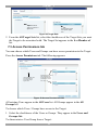
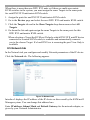
8. Management / Devices
The web interface opens at the Devices page, see Figure 34. The New Devices
section automatically displays all IP devices detected by the KVM.net II system.
(For IP devices to appear they must be configured to be KVM.net enabled – see
section 8.1 below). Each device appears identified by its MAC address. The MAC
address of each IP device is written on a sticker on the unit’s underside. Once the
device is configured by giving it a name, it then only appears in the Devices
section. The New Devices section itself only appears when there are new devices
detected.
New devices identified
with their MAC address
To sort the devices in
alphabetical order A-Z or
Z-A, click the top of the
name column
Menu section
IP device type
To search for a device
type name here and
click the search icon
Click the arrows to show
or hide New Devices/
Devices section
Once devices are
identified by a
name they appear
here in the Devices
section
Click a name to edit the
devices properties
Figure 34 Devices page
The columns on the Devices page display the following information:
Name – Once IP devices are given an identifying name they appear here.
Type – Connected IP device type.
Connected User – User currently operating the remote session.
Status
Under the Status column, there are the following possibilities:
Online – The device is up and running and is ready to be configured or is
available for a remote session.
Alarm – Device is down and is unavailable for a remote session.
38
USER GUIDE
Warning – Problem with the device. See the Devices page on page 39 for
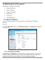
more information.
Uploading – Device is receiving new firmware from KVM.net II Manager.
Updating device – Device is receiving an updated configuration from
KVM.net II Manager.
Rebooting - Device reboots upon any Network parameter change, or firmware
upgrade.
Connecting – KVM.net II send or receives the Device Discovery message.
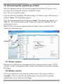
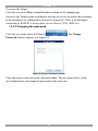
Version – Displays the device firmware version number.
Description – Identifying description of the device as input by the administrator
when configuring the device.
8.1 Setting each IP device to be KVM.net enabled
In order to be managed by KVM.net II, all Minicom IP devices must be configured
to be KVM.net enabled. See section 4 on page 16.
Tip! Since IP devices only appear in the New Devices list once they are KVM.net
enabled, make each IP device KVM.net enabled in a certain order with a suitable
time gap, so that you can identify the unit’s location.
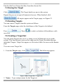
8.2 Configuring the IP devices in the KVM.net II
Configure a new IP device as follows:
1. In the New Devices section click the MAC address of an IP device. The
General tab of the Devices page appears, see Figure 35.
Figure 35 Devices page - General tab
Type – IP device type, PX etc. (Read-only field).
39
KVM.NET ® II
Name - You must assign a unique name to each IP device before associating
connected Targets or KVM switches. Type a name for the device.
Description – These are optional fields used for device identification.
Status – This is the connection status.
Device Info - contains information about the device, including its operational
status and version numbers of firmware, KME (keyboard, mouse emulation),
hardware, SDF (switch definition file) and date and time of last configuration
update.
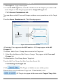
8.2.1 The Advanced button
When required, you can change the performance and mouse settings (the Set
mouse and performance from KVM/IP Session must be unchecked on the
Settings/Global Settings page - see section 9.4.1 on page 58).
To do so:
Press
. The following appears:
Figure 36 Advanced page
8.2.2 Performance
Bandwidth has the following options from the drop-down menu:
High
For optimal performance while working with a Local Area (LAN) connection,
select High bandwidth. This will adjust the performance to low compression and
high color (16bit).
Low
For optimal performance when using a Dialup connection, select Low bandwidth.
This will adjust the performance to high compression and 16 colors. For improved
performance, verify that the Color selection is a 16 colors palette.
Medium
When working on DSL, cable or ISDN connections, select Medium.
40
USER GUIDE
Custom
Custom gives you the option to manually choose both the compression and colors.
8.2.3 Mouse
Select the appropriate values according to the type of mouse connected to the
device.
Type - Select the mouse type you would like IP device to emulate. When setting
the mouse emulation type, set it to match the mouse connected to the Local
Console port on the IP device, e.g. if the local mouse is a 2 button mouse, but not
from Microsoft set the Mouse Emulation type to Standard Mouse and uncheck the
Microsoft checkbox.
Tip! The mouse on most KVM drawers in a standard rack is a Standard Mouse
Microsoft - Uncheck this box if the mouse does not work using Microsoft mouse
protocol.
Important!!
We recommend not changing the Advanced settings unless there is erratic mouse behavior.
E.g. the mouse makes random clicks and jumps arbitrarily around the screen.
Press Apply to save changes and return to the Device Properties page.
41
KVM.NET ® II
8.3 KVM Ports tab
In the KVM Ports tab you:
•
•
Associate the KVM switches in the system to the relevant IP device
Associate Targets with the relevant IP device/port number on the KVM
switch
Click the KVM Ports tab, the following appears.
Ports numbers for the
selected KVM switch
appear here
Target servers appear
here
Figure 37 KVM Ports tab
The KVM switch drop-down list consists of pre-selected KVM switches. You must
select all the KVM switch types physically connected to the system, this is done in
the Settings part of the menu and is explained in section 9.2 on page 49. Select the
KVM switch model (if any) physically connected to this IP device. The number of
ports in the selected KVM switch appears in the Ports section.
Notes:
When using a Smart 116 IP, “IP 116” is selected by default and cannot be altered.
When using a Smart 216 IP or Smart 232 IP, “Internal” is selected by default and
cannot be altered.
8.3.1 DXU IP II units
When there are DXU IP II units in the system:
For KVM.net enabled select the correct DX configuration with Ctrl (and not
PRT-SCR hotkey), as selected in the KVM Switches page.
42
USER GUIDE
For KVM.net managed select the correct DX configuration with PRT-SCR (and
not Ctrl hotkey), as selected in the KVM Switches page. Once the correct DX
configuration with PRT-SCR is selected, the fields circled in Figure 38 appear.
Figure 38 DXUIP II fields in KVM.net II Managed mode
If this DX User IP II is the IP device connected to User port 1 of the DX Central,
select the Master Console checkbox. (This enables the DX port statuses to be
displayed in the KVM.net II interface). If this unit is not the Master console, select
the User port this device is connected to from the Console port drop-down list and
select the Master device from the Master device drop down list.
Note! When there are more than one DXU IP II units in the system you must select
the KVM switch file for all DXU IP II units.
8.4 Targets
The Targets you created appear in the Targets list.
You can choose to display all Targets or just unassigned Targets (default) or
Targets belonging to a Target set. Select the desired option from the Show Targets
drop-down menu.
You must associate the Targets with the relevant IP device or with the port
numbers on the KVM switch to which they are physically connected.
To associate the Targets:
1. From the Targets list, double-click the Target connected port #1 of the KVM
switch. The Target assigns to the port #1 of the Ports section. Alternatively drag
and drop the Target to the correct port number.
2. Repeat the above step for all Targets connected. Ensure the right Target assigns
to the correctly numbered port.
To remove a Target from a port:
Double-click the Target in the Ports section. The Target name moves to the Target
section and is now unassigned.
Note! Deleting a Target removes its association with the KVM port number. See
page 35.
43
KVM.NET ® II
When there is more than one DXU IP II units or if there are multi-user matrix
KVM switches in the system, you must assign the same Targets to the same ports
for each DXU IP II unit/matrix KVM switch.
1. Assign the ports for one DXU IP II unit/matrix KVM switch.
2. Go to the Devices page and select the next DXU IP II unit/matrix KVM switch.
3. Click the Targets tab and in the Show Targets drop-down menu select All
Targets.
4. Go down the list and again assign the same Targets to the same ports for this
DXU IP II unit/matrix KVM switch.
When selecting a Target the KVM.net II checks which DXU IP II unit/IP device
connected to a matrix KVM switch, is available and automatically connects
you to the chosen Target. If a local DX User is accessing the port View Only is
available.
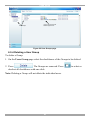
8.5 Network tab
In the Network tab you configure and modify Network parameters of the IP device.
Click the Network tab. The following appears.
Figure 39 Network tab
Interface I displays the IP address of the IP device as discovered by the KVM.net II
Manager system. You can change this address here.
Enter IP address, Subnet Mask and Default Gateway for the network adapter, as
given by your Network Administrator.
44
USER GUIDE
In TCP Ports type three ports (from 800 and up to 65535). By default the port
numbers are 900, 901 and 902. These default ports are suitable for the majority of
installations.
Click to clear or select the following according to your requirements:
DHCP – Enable DHCP to provide you with dynamic IP addressing for the IP
device, if a DHCP server exist.
Note: Any change in the Network configuration forces the IP device to restart.
8.5.1 Serial tab
In the Serial tab you define the console parameters for controlling RS232 Serial
devices for KVM/IP units.
Click the Serial tab. The following appears.
Figure 40 Serial tab
You can access a Serial device during a remote session by emulating its Serial
connection via RS232 (VT100 & TTY). Only users with administrative privileges
can operate Serial devices (such as a Power management device).
Device Name - Type the name of the device (i.e. Power Management; Cisco
router; etc)
Baud Rate, Data Bits, Parity, Stop bits - type the appropriate values according to
the RS232 device line settings, attached to the KVM/IP device.
Active – Select Active to display the device on the Client toolbar.
8.6 Saving the IP device configuration changes
Press Save to save the settings and configure the IP device. The IP device is
upgraded to the device firmware stored in the KVM.net II system. It receives the
SDF from the KVM.net II system and also a list of Targets, Users and their
permissions (CFG). The IP device may be unavailable during the upgrade and
while receiving the CFG and SDF updates.
45
KVM.NET ® II
8.7 Deleting IP devices
IP devices can be deleted from the KVM.net II system from the Devices page.
To delete IP devices:
1. From the Management menu, click Devices the Devices page appears.
2. Select the checkboxes of the units to be deleted, or select the top checkbox to
select or deselect all checkboxes.
. The devices are deleted.
3. Click
4. Uncheck Enable KVM.net on the device’s Network Configuration Web page.
This will prevent the deleted IP device from being rediscovered.
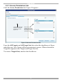
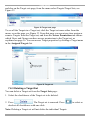
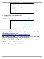
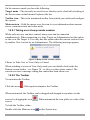
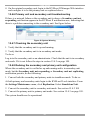
8.8 Device discovery
The status of the IP devices is updated automatically every minute. You can
manually discover new devices at any time from the Devices page.
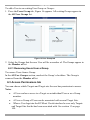
To do so:
In the menu, right-click Devices, the Discovery menu appears, see Figure 41. Click
Discover Now. The KVM.net II Manager performs a device discovery on the
network segment. All newly discovered devices appear in the New Devices section.
Figure 41 Devices page - Discovery
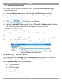
9. Settings - Applications
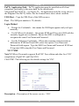
From the menu, click Settings. The Access Services page appears see Figure 42.
The Settings are split into Applications and Maintenance sections.
In the Applications section you configure:
•
Access Services
•
KVM Switches
•
Account Policy
•
Global Settings
46
USER GUIDE
9.1 Access services
Besides connecting to Minicom KVM/IP devices, you can connect to a variety of
both hardware and software external resources from the KVM.net II interface as
follows:
•
Minicom PX Serial
•
Web service
•
ILO - HP Integrated Lights-Out (iLO)
•
RDP - Remote Desktop Protocol
•
SSH - Secure Shell
•
VNC- Virtual Network Computing
•
Telnet- TELecommunication NETwork
•
VMware Server
See page 14 - 15 for an elaboration of the above services.
From the Access Services page you can configure access services for Targets in the
system. You can also add new Access services from this page.
Checkboxes are greyed
out for factory included
access services – these
cannot be deleted.
Figure 42 Access Services
Outlined below, is the default template values for Minicom KVM/IP devices. If
these values are not suitable you can change them.
For the default template values of the other factory included Access Services, see
section 10 on page 60.
47
KVM.NET ® II
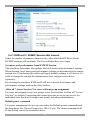
9.1.1 Minicom KVM/IP
Click Minicom KVM/IP. The Minicom KVM/IP settings appear, see Figure 43.
Figure 43 Minicom KVM/IP settings
The default elements of the Minicom KVM/IP settings as follows:
Note! Only change the default settings if the large majority of the Targets in the
system have settings that are different to the default settings.
Description – This is the description of the Access service - Minicom KVM/IP
device.
Operating System – Default operating system is Windows 2003 Server/Windows
XP. This setting is suitable for Windows XP, Vista, 2003 Server and 2008 Server.
If the large majority of the Targets in the system have a different operating system,
select it from the Drop-down list. The mouse parameter options adjust to match the
operating system.
Acceleration / Threshold – When the Target’s mouse settings are not default
select the appropriate values. Match the values to that of the server’s mouse.
Note! (Relevant to all IP devices except PX USB) For Windows XP, 2003 Server, Vista
and 2008 Server. Go to the Mouse settings on the Target and uncheck Enhance
pointer precision.
USB Converter - When a KVM/IP device connects to a server via a USB to PS/2
adapter, or RICC/ROC USB, or X RICC USB or Specter USB, select the USB
Converter checkbox. The USB conversion affects the mouse emulation and the
USB Converter helps to synchronize the mouse.
Absolute Mouse – (Relevant only for PX USB) If the operating system on the
Target is, Windows ME or higher, then Absolute Mouse checkbox should be
selected.
48
USER GUIDE
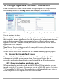
9.2 KVM switches
Configuring KVM switches is relevant when there are KVM switches connected to
IP devices in the system or when there are DXU IP II units in the system. You must
select all the KVM switch types physically connected.
To select the KVM switch types:
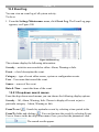
1. From the Application menu, select KVM Switches. A list of KVM switches
appears, see Figure 44. The columns show the following:
•
Model - KVM switch model
•
Manufacturer - KVM switch manufacturer
•
Ports - The number of server ports
•
Power Enabled - Power enabled status. Where the KVM switch is
connected to a power management device such as a Minicom Remote Power
Switch or Power on Cable, the status of this column is yes meaning it is
power enabled. No means it is not enabled.
•
Matrix – The number of simultaneous users this switch supports. Note!
Where you know a KVM switch has matrix capabilities, but no number
appears in the Matrix column, contact the Minicom Support team to obtain
the updated SDF of the KVM switch. Uploading the SDF is explained in
section 9.2.1 below.
Figure 44 KVM Switches
49
KVM.NET ® II
2. From the list, select the KVM switch brands and models physically connected
to your IP devices. When there are Smart 116 IP units in the system, select IP
116 from the list.
When there are DXU IP II units in the system:
For KVM.net enabled select the correct DX configuration with Ctrl (and not
PRT-SCR hotkey). For example when there is 1 DX Central unit in the DX
system, select Minicom DX System (32 ports Ctrl). When there are 2 DX
Central units in the DX system select Minicom DX System (64 ports Ctrl).
For KVM.net II managed select the correct DX configuration with PRT-SCR
(and not Ctrl hotkey). For example when there is 1 DX 432 Central unit in the
DX system, select Minicom DX4x32 (PRT-SCR). When there are two 832 DX
Central units in the DX system select Minicom DX8x64 (PRT-SCR).
3. Press
. The selection is saved.
9.2.1 Uploading a new KVM Switch
If a KVM switch is not listed, contact Minicom at support@minicom.com to obtain
a new KVM switch definition file (SDF).
When you receive the file do the following:
1. Save the KVM switch file on your computer’s hard disk.
2. Login to KVM.net II as an Administrator.
3. From the KVM Switches page - see Figure 44 - press
KVM switch file (SDF.XML).
4. Press
list.
to locate the
. The file uploads with the new switch type added to the
5. Select the KVM switch type and click
.
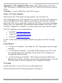
9.3 Account Policy
In Account Policy you can choose either local or external authentication. In local
authentication you define password and login complexity levels. External
authentication interfaces with the organizational Active Directory server for user
list importation.
In local authentication mode the administrator creates Users and Groups and
assigns permissions via the KVM.net II interface. In LDAP authentication mode
server option authentication is done through an LDAP server. You import Users
and Groups from the LDAP server.
50
USER GUIDE
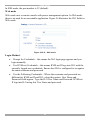
To set these options:
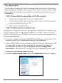
From the Application menu select Account Policy. The Account policy page
appears, see Figure 45.
Figure 45 Account policy
9.3.1 Password policy
When KVM.net II operates in local authentication mode, choose the desired
password policy. The different password policy options are explained below.
Note! The following “special” characters: &, <, >, ”, cannot be used for either the
user name or password in any of the password levels. (See page 22).
Strict Policy password:
•
8 characters or more
•
Must include at least
•
•
•
•
1 digit and
1 upper case letter and
1 “special” character as follows: !.@#$%^ *( )_-+= [ ]{ }
Must not include the user name
Standard Policy password:
•
6 characters or more
•
Must not include the user name
51
KVM.NET ® II
None:
You can write any character (except the “special” characters: &, <, >, ”,) and any
number of characters for the password. (See page 22).
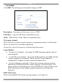
9.3.1.1 Account blocking
You can block entry into the system after a number of unsuccessful attempts by a
user inputting the wrong password.
To do so:
1. Select the Account blocking checkbox. The following appears.
Figure 46 Account blocking
Choose the number of attempts within a time period and for how long to block the
account for.
9.3.2 External authentication (LDAP)
LDAP, (Lightweight Directory Access Protocol), is a standard protocol for
accessing information in a directory.
LDAP defines processes by which a client can connect to an X.500-compliant or
LDAP-compliant directory service to add, delete, modify, or search for
information, provided the client has sufficient access rights to the directory. For
example, a user could use an LDAP client to query a directory server on the
network for information about specific users, computers, departments, or any other
information stored in the directory.
Note! KVM.net II supports Windows 2003 and Windows 2008 Active Directory
LDAP Authentication.
9.3.2.1 KVM.net II in External authentication (LDAP) mode
In External authentication (LDAP) mode, KVM.net II deletes all users created
before in Local authentication mode. New users can only be imported from a
Windows 2003 or Windows 2008 Active Directory.
KVM.net II will validate all user credentials against the external LDAP server
only.
52
USER GUIDE
Only the “admin” account remains as a “backdoor” account. This user has
KVM.net II local access. Admin account is allowed to manage KVM.net II with
"Administrator" access privileges. However, "admin" is not permitted to connect
to Targets. This account will allow changing KVM.net II to Local authentication
mode at any time.
There is no direct access to any IP device. KVM.net II will act as a gateway.
Since the KVM.net II user accounts are kept in the local database, it can happen
that some of the local accounts do not have related LDAP objects (e.g. some user's
account might migrate to another LDAP path). To clean the local database from
those ghost accounts that will never pass LDAP authentication, KVM.net II
provides the customers with the manual synchronize operation.
Users Groups will not be deleted and will be managed locally after its import.
When changing KVM.net II to Local authentication mode, all the users appear as
“inactive”. To re-activate the users, the Administrator must explicitly provide each
account with a local password.
9.3.2.2 DNS setting in LDAP mode
Important! The correct DNS setting is vital for the successful configuration of the
KVM.net in LDAP mode. You set the KVM.net DNS settings in the Settings / Unit
Maintenance / Network tab. See section 16.2 on page 114.
9.3.2.3 LDAP settings
1. Select the External Authentication tab, the LDAP settings appears, see Figure
47.
Figure 47 LDAP settings
2. Select the Use LDAP authentication server checkbox.
3. Input details of the Active Directory:
53
KVM.NET ® II
Base DN – here you define the base object where the search for users begins. The
search is performed only on this object and the objects below it in the directory
tree. The Base DN string has the standard LDAP syntax: CN=(Common Name…),
OU=(Organizational Unit), DC=(Domain Component). Base DN should be in the
following format DC=domain,DC=tld. For example for the domain kvm.net.org,
the Base DN should be DC=kvm,DC=net,DC=org.
Host – Type the Host name or (preferably) the IP address of the Active Directory
DC server.
Port - Type the LDAP port number. If left blank; KVM.net II uses the default
LDAP port 389 (which is the default port for most LDAP servers including
Microsoft Active Directory).
Bind DN – Also known as “User DN” or “Append”. The Bind DN is a
distinguished name of an LDAP object, which serves a gateway to the LDAP
directory. Prior to sending the account/password pair, KVM.net II initiates a
conversation handshake with LDAP. This handshake protocol in general needs a
"Bind DN/Bind password" pair to decide, whether the KVM.net II client is
permitted to query the LDAP directory server. (For example if we have user
Minicom in group Users in domain kvm.net.org the Bind DN should look like this:
CN=minicom,CN=users,DC=kvm,DC=net,DC=org).
Type the Active Directory objects you would like to search and the user account
that will be used to perform this operation.
Password – Type the password for the user account given in the Bind DN.
4. Click
. The system queries the Active Directory. (This may take
some time). The
and
buttons become enabled.
9.3.2.4 Importing users
To import users, press
, the Import Users window appears, see
Figure 48. Here you see all the Groups in the Active Directory.
To display the Users in a directory, expand the Group.
Notes:
•
Users must be members of groups in order to be shown in the Import Users
Active Directory tree. Users belonging to the container “Users” in the Active
Directory, do not necessarily belong to any Group.
•
You can use the Active Directory command “dsquery user” to list all
Active Directory users with their correct Bind DN parameters. Run “dsquery
user” at the command prompt of your Active Directory Domain Contoller.
54
USER GUIDE
Imported user groups
appear here
All LDAP users and
groups appear here.
Groups can be
expanded to select just
individual users.
Imported users appear
here
Figure 48 Import LDAP Users window
You can import:
•
•
A Group with all its users by selecting the Group.
Some users of a Group by expanding the Group and then selecting the
desired users.
Once selected, the Groups and Users appear in the Selected User Group/User
area. Press Save, a prompt appears explaining that all current KVM.net users will
be deleted
. Press OK. The Groups and Users appear in
the Users/Groups section of the KVM.net II, with the words “Users (LDAP mode)”
at the top of the page, see Figure 49.
55
KVM.NET ® II
Figure 49 Users (LDAP mode)
After importing Users, you must assign their permissions - Administrator, User, or
View only. How to assign permissions is explained in section 6 on page 21. By
default all Users have User permission status. (Also assign their Target permissions
and allowed Access Services).
9.3.2.5 Synchronization
Synchronization does two things:
•
Keeps the exact group structure maintained on the LDAP servers.
(Whenever a user is added or removed from the LDAP server group, it will
be synchronized with the KVM.net II).
•
Removes deleted users. A user that resides in KVM.net II but is deleted
from the LDAP server will be removed from KVM.net II as well.
Where users and/or Groups have been added or deleted from the LDAP database,
you can synchronize the local user database with the LDAP database. There is no
need to import new users from the LDAP database, synchronization does this
automatically, provided that the new user is added to one of the groups imported
into the KVM.net II.
To synchronize:
Click
. The local user database is compared to the LDAP database.
Any local user that does not exist on the LDAP server is noted as deleted. Any new
user added to already imported KVM.net II Groups in the LDAP database is noted
as added, see Figure 50.
Note: To add a user to the KVM.net II Groups using the synchronize function, add
this user to the imported Group in the LDAP server.
56
USER GUIDE
Figure 50 Purge window
9.3.2.6 Operating KVM.net II in External Authentication mode
In External Authentication (LDAP) Mode, KVM.net II Manager will no longer
allow login for the users that were created in Local Authentication mode. These
users will be deleted. New users will be imported from Active Directory.
KVM.net II Manager will validate all user credentials against the LDAP server
only.
Only the “admin” account retains local authentication as a “backdoor” account.
This user has KVM.net II local access. Admin account is allowed to manage
KVM.net II with "Administrator" access privileges. However, "admin" is not
permitted to connect to Targets. This account will allow reversing the External
Authentication Mode at any time to local authentication mode.
There is no direct access to any IP device, even to its Configuration page. KVM.net
II will act as a gateway.
When changing KVM.net II to Local Authentication mode, all imported users
appear as “inactive”. To re-activate the users, the administrator must set a password
for each account.
Clicking the New User button on the Users page - see page 21 - opens the Import
LDAP Users window.
9.4 Global Settings
In Global Settings, you can change the idle timeout period and set out global
parameters as explained below.
From the menu click Global Settings, the following appears.
57
KVM.NET ® II
Figure 51 Global Settings
9.4.1 KVM.net II / KVM/IP Session Idle timeout
Select the number of minutes of non-activity, after which the KVM.net II and
KVM/IP sessions will terminate. The User will then have to re-login.
Set mouse and performance from KVM/IP Session
This checkbox determines who updates the local mouse and performance settings.
When checked, local mouse and performance settings are determined at the remote
session level. Unselecting this option will apply defaults settings to all devices. In
order to change the settings the administrator must configure each device
separately.
By selecting the checkbox KVM.net II will not overwrite local mouse and
performance settings made in the client toolbar.
Allow all "Access Services" for users without group assignment
For users not assigned to any user groups select the checkbox to allow all "Access
Services" by default. Unselecting this option prevents access to any service for
individual users that don’t belong to any group, including administrators.
Default power command
For power management devices you can select the Default power command from
the drop-down list. Choose Prompt, On, Off or Cycle. The chosen command will
be the default sent to the connected device.
58
USER GUIDE
Items Per Page
Select the maximum number of items – Targets, Groups etc – to appear on one
page. When this number is reached additional items are put on another page. You
click on the page link to open the next page.
Click Save to save changes.
59
KVM.NET ® II
10. Configuring Access Services – introduction
Each Access Service comes with a default settings template. The template values
can be changed from the Settings/Access Services page, see Figure 52.
Checkboxes are greyed
out for factory included
access services – these
cannot be deleted.
Figure 52 Access Services
The template values are automatically applied to new Targets that have the Access
Service assigned to them.
For example, there is a default value for the application path of an access service. If
this is suitable, ensure that all users have the access service application in the same
path on their computer. Where a user computer has a different path, a prompt
appears on the user’s computer asking the user to browse for the Access Service
application on his computer.
Note! Access Service settings can also be changed if necessary, for individual
Targets, explained on page 72.
All the Access Services are reached from the Access Services page, see page 47.
10.1 Access Services default values
Below are the factory included access services and their default values. If these
values are not suitable you can change them. If an Access Service has an
executable application, the application must be installed on all local computers.
10.1.1 General note about application paths
When inputting the application path into the KVM.net II client interface you can
include variables. For example for an access service called ABC service, by typing
“%ProgramFiles%\ABCservice” the application could be installed in any drive on
client computers in the Program Files\ABCservice folder.
60
USER GUIDE
The following variables in the application path can be used:
•
%ProgramFiles% - Program Files folder
•
%SystemRoot%\ - Windows folder
10.1.2 Minicom PX Serial
Click Minicom PX Serial. The Minicom PX Serial settings appear, see Figure 53
Figure 53 Minicom PX Serial settings
Description: - Description of the access service - Minicom PX Serial.
Application: - PuTTy.exe is application used and it must be installed on all client
computers, see the paragraph below.
The PuTTy application can be obtained from:
http://www.chiark.greenend.org.uk/~sgtatham/putty/download.html
Path: - PuTTy application must be installed on all client computers, preferably in
the same path. In the default path %ProgramFiles%\PuTTy, see Figure 53, the
application could be in any drive in the Program Files\PuTTy folder. See the
General notes above about variables.
URL/Host: - Type the URL/Host of the Minicom PX Serial.
Port: - The Minicom PX Serial, TCP port number is 4000.
61
KVM.NET ® II
10.1.3 Web
Click Web. The Web settings appear, see Figure 54.
Figure 54 Web Target
Description: - Default description.
Set the URL for each individual web page as explained on page 73.
10.1.4 ILO
Click ILO. The ILO settings appear, see Figure 55.
Figure 55 ILO – SSH mode
Description – Description of the access service - ILO.
URL/Host – Type the URL/Host of the ILO resource.
Port / Application / PuTTy Application Path – these fields are only relevant in
SSH mode. The difference between SSH and Web mode is detailed below.
SSH mode (default)
SSH mode uses an ILO console server. In SSH mode the PuTTy application must
be installed on all client computers, preferably in the same path. In the default path
%ProgramFiles%\PuTTy - see Figure 55 – the application could be in any drive in
the Program Files\PuTTy folder. See the General notes above about variables.
The PuTTy application can be obtained from:
http://www.chiark.greenend.org.uk/~sgtatham/putty/download.html
62
USER GUIDE
In SSH mode, the port number is 22 (default).
Web mode
Web mode uses a remote console with power management options. In Web mode
there is no need for an executable application. Figure 56 illustrates the ILO fields in
Web mode.
Figure 56 ILO – Web mode
Login Method:
•
Prompt for Credentials – this means the ILO login page appears and you
login manually.
•
Use KVM.net Credentials – this means KVM.net II logs into ILO with the
currently logged user credentials. Ensure that ILO is configured to recognize
the same username and password.
•
Use the Following Credentials – Where the username and password are
different for KVM.net II and ILO, select this option. User Name and
Password fields appear. Type the ILO User Name and Password. KVM.net
II logs into ILO using this User Name and password.
63
KVM.NET ® II
10.1.5 RDP
Click RDP. The following are the default settings for RDP.
Figure 57 RDP– Web mode
Description: - Description of the access service - RDP.
URL/Host: - Type the URL/Host of the RDP resource.
Mode: - RDP Client or Web. These are explained below.
Web mode (default)
Web mode uses a remote console with power management options. In Web mode
there is no need for an executable application.
Screen Size: select the screen size from the drop-down menu.
Login Method: •
Prompt for Credentials – this means the RDP login page appears and you
login manually.
•
Use KVM.net Credentials – this means KVM.net II logs into RDP with the
currently logged user credentials. Ensure that the Target computer is
configured to recognize the same username and password.
•
Use the Following Credentials – Where the username and password are
different for KVM.net II and the Target computer, select this option. User
Name and Password fields appear. Type the RDP User Name and Password.
KVM.net II logs into the Target computer using this User Name and
Password.
RDP Client mode
When selecting RDP Client mode, the page appears as in Figure 58.
64
USER GUIDE
Figure 58 RDP – RDP Client mode
RDP Client mode uses an RDP console server. From Windows XP onwards the
executable application - mstsc.exe - comes as part of the operating system. For
Windows 2000 download the Client portion of the Remote desktop software from
the Microsoft website.
RDP Application Path: - The RDP application must be installed on all local
computers, preferably in the same path. In the default path
%SystemRoot%\System32 the application could be in any drive in the
Windows\System32 folder. See the General notes above about variables.
In RDP Client mode there is only manual login.
10.1.6 SSH
Click SSH. The following are the default settings for SSH.
Figure 59 SSH
Description: - Description of the access service - SSH.
Application - PuTTy.exe is the application used for SSH access. The PuTTy
application can be obtained from:
http://www.chiark.greenend.org.uk/~sgtatham/putty/download.html
65
KVM.NET ® II
PuTTy Application Path: - PuTTy application must be installed on all client
computers, preferably in the same path. In the default path
%ProgramFiles%\PuTTy – see Figure 59 – the application could be in any drive in
the Program Files\PuTTy folder. See the General notes above about variables.
URL/Host: - Type the URL/Host of the SSH resource.
Port – The SSH port number is 22 (default).
Login Method
•
Prompt for Credentials – this means the SSH login appears and you login
manually.
•
Use KVM.net Credentials – this means KVM.net II logs into SSH with the
currently logged user credentials. Ensure that SSH is configured to
recognize the same User Name and Password.
•
Use the Following Credentials – Where the username and password are
different for KVM.net II and SSH, select this option. User Name and
Password fields appear. Type the SSH User Name and Password. KVM.net
II logs into SSH using this User Name and Password.
10.1.7 VNC
Note! KVM.net II currently supports RealVNC Free edition and other free VNC
compilations (TightVNC and UltraVNC).
Click VNC. The following are the default settings for VNC.
Figure 60 VNC – VNC Client mode
Description: - Description of the access service - VNC.
66
USER GUIDE
Application / VNC Application Path / Port – these fields are only relevant in
VNC Client mode. The difference between VNC Client and Web mode is detailed
below.
URL/Host: - Type the URL/Host of the VNC resource.
Mode: VNC Client (default)
When using VNC Client mode, the page appears as in see Figure 60.
VNC Client mode uses a VNC console server. In VNC Client the VNC application
must be installed on all client computers, preferably in the same path. Type the
path to the VNC Viewer application. Where the VNCPath is the actual installation
folder of the VNC application, the installation folder depends on the type of VNC:
RealVNC, TightVNC or UltraVNC. See the General notes above about variables.
The VNC application can be obtained from:
•
RealVNC: http://www.realvnc.com
•
TightVNC: http://www.tightvnc.com/
•
UltraVNC: http://www.uvnc.com/
In VNC Client mode, the port number should correspond to the VNC listening
port.
Login Method:
•
Prompt for Credentials – this means the VNC login appears and you login
manually.
•
Use KVM.net Credentials – this means KVM.net II logs into VNC with
the currently logged user credentials. Ensure that VNC is configured to
recognize the same password.
•
Use the Following Credentials – Where the passwords are different for
KVM.net II and VNC, select this option. A Password field appears. Type the
VNC Password. KVM.net II logs into VNC using this Password.
Web mode
In Web mode there is no need for an executable application.
When selecting Web mode, the page appears as in Figure 61.
67
KVM.NET ® II
Figure 61 RDP – Web mode
In Web mode there is only manual login.
10.1.8 Telnet
Click Telnet. The following are the default settings for Telnet.
Figure 62 Telnet
Description: - Description of the Access service - Telnet.
Application - PuTTy.exe is the application used for Telnet access. The PuTTy
application can be obtained from:
http://www.chiark.greenend.org.uk/~sgtatham/putty/download.html
PuTTy Application Path: - - PuTTy application must be installed on all client
computers, preferably in the same path. In the default path
%ProgramFiles%\PuTTy – see Figure 62 – the application could be in any drive in
the Program Files\PuTTy folder. See the General notes above about variables.
URL/Host: - Type the URL/Host of the Telnet resource.
Port – The Telnet port number is 23 (default).
68
USER GUIDE
10.1.9 VMware Server
Click VMware Server. The following are the default settings for VMware Server.
Figure 63 VMware Server
Description: - Description of the access service - VMware Server.
Virtual Server Host or IP: - Type the Host/IP of the VMware Server resource.
Application - vmware.exe is the application used for VMware Server access. The
VMware Server Client application can be obtained from:
http://www.vmware.com/download/server/
Application Path: - VMware Server console must be installed on all client
computers, preferably in the same path. In the default path %ProgramFiles%\
VMware\VMware Server Console – see Figure 63 – the application could be in any
drive in the Program Files\VMware\VMware Server Console folder. See the
General notes above about variables.
Virtual Machine Path - Type the Virtual Machine Path on the VMware Server.
Login Method:
•
Prompt for Credentials – this means the VMware Server Console login
appears and you login manually.
•
Use KVM.net Credentials – this means KVM.net II logs into VMware
Server Console with the currently logged user credentials. Ensure that
VMware Server is configured to recognize the same User Name and
Password.
•
Use the Following Credentials – Where the User Name and Password are
different for KVM.net II and VMware Server, select this option. User Name
and Password fields appear. Type the VMware Server User Name and
69
KVM.NET ® II
Password. KVM.net II logs into VMware Server using this User Name and
Password.
10.1.10 New Access Services
You can add other access services. If the new service has an executable application
the application must be installed on all client computers, preferably in the same
path.
Add new Access Services as follows:
. The New Service
1. From the Access Services page click
page appears, see Figure 64. This page is a template for configuring a new
access service.
Figure 64 New Service page
Fill in the fields that are relevant to the service as follows:
Name - Name of the Access service.
Description – Description of the access service.
70
USER GUIDE
URL – If the Access service resource can be reached via a web browser, type the
URL here: HTTP or HTTPS etc. You may incorporate variables such as into the
URL as follows:
•
%ProgramFiles% - Program Files folder
•
%SystemRoot%\ - Windows folder
•
%IP% - IP address (IP checkbox must be selected)
•
%Port% - TCP port number (Port checkbox must be selected)
•
%UserName% - Login User name.
•
%Password% - Login Password. Login Method checkbox must be
selected.
Application Path – if the new service has an executable application the application
must be installed on all client computers, preferably in the same path. The
application could be in any drive in e.g. the following folder %ProgramFiles%\Access service. Type the Application Path and executable name,
including all command line switches, options and parameters.
IP – Where relevant type the IP address of the Access service resource.
Port – Where relevant, type the port number.
Login Method: If you need a login method choose from the following:
•
Prompt for Credentials – this means the access service login appears and
you login manually.
•
Use KVM.net Credentials – this means KVM.net II logs into the access
service with the currently logged user credentials. Ensure that the access
service is configured to recognize the same User Name and/or Password.
•
Use the Following Credentials – Where the User Name and Password are
different for KVM.net II and the access service, select this option. User
Name and Password fields appear. Type the access service User Name
and/or Password. KVM.net II logs into the access service using this User
Name and/or Password.
Save the new service. The new service appears on the Access Services page.
71
KVM.NET ® II
11. Configuring Access services for individual Targets
As explained in section 10, the Access service default values are set globally in the
Settings section of the menu – in Applications/Access Services. The following
sections explain how to configure each Access service for individual Targets.
You configure the Access Services for each Target from the Access Services tab,
as follows:
1. From the Management menu, select Targets, the Targets page appears see
Figure 65.
Click here to display the
Targets page
Total number of
Targets in the
system
Figure 65 Target page
2. For new Targets click the New Target button, for existing Targets click the
target name in the name column. The Access Services tab appears.
11.1 Default access service
You can set any of the access services to be the default service. This means that the
service will be used to access the Target by default when selecting the Target
name. To access the Target via a different service, the service must be selected. To
set a service as the default, display the service as explained below and select the
Set as Default Service checkbox.
11.2 Minicom PX Serial
To configure a Minicom PX Serial:
1. From the All Services list, select the Minicom PX Serial checkbox. Minicom
PX Serial now appears in the Active Services list.
2. Click Minicom PX Serial. The Minicom PX Serial settings appear, see Figure
66.
72
USER GUIDE
Figure 66 Minicom PX Serial settings
Description: - Description of the access service - Minicom PX Serial.
Application: PuTTy.exe. This application must be installed on all client
computers.
Path: - Path of the PuTTy application. Only change the default path if it is
unsuitable.
URL/Host: - Type the URL/Host of the Minicom PX Serial.
Port: - The Minicom PX Serial, TCP port number is 4000.
11.2.1 Web
From the All Services list, select the Web checkbox. Web appears in the Active
Services list.
Click Web. The Web settings appear, see Figure 67.
Figure 67 Web Target
Description: - Description of the Web service.
URL: - Set the URL for each individual web page here.
73
KVM.NET ® II
11.2.2 ILO
From the All Services list, select the ILO checkbox. ILO appears in the Active
Services list.
Click ILO. The ILO settings appear, see Figure 68.
Figure 68 ILO
Description – Description of the access service - ILO.
URL/Host – Type the URL/Host of the ILO resource.
Port / Application / PuTTy Application Path – these fields are only relevant in
SSH mode. The difference between SSH and Web mode is detailed below.
SSH mode (default)
SSH mode uses an ILO console server. In SSH mode the PuTTy application must
be installed on all client computers, preferably in the same path. In the default path
%ProgramFiles%\PuTTy the application could be in any drive in the Program
Files\PuTTy folder.
The PuTTy application can be obtained from:
http://www.chiark.greenend.org.uk/~sgtatham/putty/download.html
In SSH mode, the port number is 22 (default).
See below for Login method.
74
USER GUIDE
Web mode
Web mode uses a remote console with power management options. In Web mode
there is no need for an executable application. Figure 56 illustrates the ILO fields in
Web mode.
Figure 69 ILO – Web mode
Login Method:
•
Prompt for Credentials – This means the ILO login appears and you login
manually.
•
Use KVM.net Credentials – This means KVM.net II logs into ILO with the
currently logged user credentials. Ensure that ILO is configured to recognize
the same username and password.
•
Use the Following Credentials – Where the User Name and Password are
different for KVM.net II and ILO, select this option. User Name and
Password fields appear. Type the ILO User Name and Password. KVM.net
II logs into ILO using this User Name and password.
11.2.3 RDP
From the All Services list, select the RDP checkbox. RDP appears in the Active
Services list.
Click RDP. The RDP settings appear, see Figure 70.
75
KVM.NET ® II
Figure 70 RDP– Web mode
Description: - Description of the access service - RDP.
URL/Host: - Type the URL/Host of the Target server.
Mode: - RDP Client or Web. These are explained below.
Web mode (default)
In Web mode there is no need for an executable application.
When selecting Web mode, the page appears as in Figure 70
Screen Size: select the screen size from the drop-down menu.
Login Method: •
Prompt for Credentials – this means the RDP login appears and you login
manually.
•
Use KVM.net Credentials – this means KVM.net II logs into RDP with the
currently logged user credentials. Ensure that RDP is configured to
recognize the same User Name and Password.
•
Use the Following Credentials – Where the User Name and Password are
different for KVM.net II and RDP, select this option. User Name and
Password fields appear. Type the RDP User Name and Password. KVM.net
II logs into RDP using this User Name and Password.
RDP Client mode
When using RDP Client mode, the page appears as in Figure 71.
76
USER GUIDE
RDP Client mode uses an RDP console server. From Windows XP onwards the
executable application - mstsc.exe - comes as part of the operating system.
RDP Application Path: - The RDP application must be installed on all client
computers, preferably in the same path. In the default path
%SystemRoot%\System32 – see Figure 71 – the application could be in any drive
in the Windows\System32 folder..
Figure 71 RDP– RDP Client mode
In RDP Client mode there is only manual login.
11.2.4 SSH
From the All Services list, select the SSH checkbox. SSH appears in the Active
Services list.
Click SSH. The SSH settings appear, see Figure 72.
Figure 72 SSH
77
KVM.NET ® II
Description: - Description of the access service - SSH.
Application - PuTTy.exe is the application used for SSH access. The PuTTy
application can be obtained from:
http://www.chiark.greenend.org.uk/~sgtatham/putty/download.html
PuTTy Application Path: - PuTTy application must be installed on all client
computers, preferably in the same path. In the default path
%ProgramFiles%\PuTTy the application could be in any drive in the Program
Files\PuTTy folder.
URL/Host: - Type the URL/Host of the SSH resource.
Port – The SSH port number is 22 (default).
Login Method
•
Prompt for Credentials – This means the SSH login appears and you login
manually.
•
Use KVM.net Credentials – This means KVM.net II logs into SSH with
the currently logged user credentials. Ensure that SSH is configured to
recognize the same User Name and Password.
•
Use the Following Credentials – Where the username and password are
different for KVM.net II and SSH, select this option. User Name and
Password fields appear. Type the SSH User Name and Password. KVM.net
II logs into SSH using this User Name and Password.
11.2.5 VNC
From the All Services list, select the VNC checkbox. VNC appears in the Active
Services list.
Click VNC. The VNC settings appear, see Figure 73.
78
USER GUIDE
Figure 73 VNC - VNC Client
Description: - Description of the access service - VNC.
Application / VNC Application Path / Port – these fields are only relevant in
VNC Client mode. The difference between VNC Client and Web mode is detailed
below.
URL/Host: - Type the URL/Host of the VNC resource.
Mode: VNC Client (default)
When using VNC Client mode, the page appears as in Figure 73.
VNC Client mode uses a VNC console server. In VNC Client the VNC application
must be installed on all client computers, preferably in the same path. In the default
path %ProgramFiles%\VNCPath, the application could be in any drive in the
Program Files\VNCPath folder, where the VNCPath is the actual installation folder
of the VNC application. The installation folder depends on the type of VNC:
RealVNC, TightVNC or UltraVNC.
The VNC application can be obtained from:
•
RealVNC: http://www.realvnc.com
•
TightVNC: http://www.tightvnc.com/
• UltraVNC: http://www.uvnc.com/
In VNC Client mode, the port number should correspond to the VNC listening
port.
79
KVM.NET ® II
Login Method:
•
Prompt for Credentials – this means the VNC login appears and you login
manually.
•
Use KVM.net Credentials – this means KVM.net II logs into VNC with
the currently logged user credentials. Ensure that VNC is configured to
recognize the same username + password.
•
Use the Following Credentials – Where the passwords are different for
KVM.net II and VNC, select this option. A Password field appears. Type the
VNC User Password. KVM.net II logs into VNC using this Password.
Web mode
In Web mode there is no need for an executable application.
When selecting Web mode, the page appears as in Figure 61.
Figure 74 RDP – Web mode
In Web mode there is only manual login
11.2.6 Telnet
From the All Services list, select the Telnet checkbox. Telnet appears in the Active
Services list.
Click Telnet. The Telnet settings appear, see Figure 75.
Figure 75 Telnet
80
USER GUIDE
Description: - Description of the Access service - Telnet.
Application - PuTTy.exe is the application used for Telnet access. The PuTTy
application can be obtained from:
http://www.chiark.greenend.org.uk/~sgtatham/putty/download.html
PuTTy Application Path: - - PuTTy application must be installed on all client
computers, preferably in the same path. In the default path
%ProgramFiles%\PuTTy – see Figure 62 – the application could be in any drive in
the Program Files\PuTTy folder. See the General notes above about variables.
URL/Host: - Type the URL/Host of the Telnet resource.
Port – The Telnet port number is 23 (default).
11.2.7 VMware Server
From the All Services list, select the VMware Server checkbox. VMware Server
appears in the Active Services list.
Click VMware Server. The VMware Server settings appear, see Figure 76.
Figure 76 VMware Server
Description: - Description of the access service - VMware Server.
Virtual Server Host or IP: - Type the Host/IP of the VMware Server resource.
Application - vmware.exe is the application used for VMware Server access. The
VMware Server Client application can be obtained from:
http://www.vmware.com/download/server/
81
KVM.NET ® II
Application Path: - VMware Server console must be installed on all local
computers, preferably in the same path. In the default path %ProgramFiles%\
VMware\VMware Server Console, the application could be in any drive in the
Program Files\VMware\VMware Server Console folder.
Virtual Machine Path - Type the Virtual Machine Path on the VMware Server.
Login Method:
•
Prompt for Credentials – this means the VMware Server login appears and
you login manually.
•
Use KVM.net Credentials – this means KVM.net II logs into VMware
Server Console with the currently logged user credentials. Ensure that
VMware Server is configured to recognize the same username and
password.
•
Use the Following Credentials – Where the username and password are
different for KVM.net II and VMware Server, select this option. User Name
and Password fields appear. Type the VMware Server User Name and
Password. KVM.net II logs into VMware Server using this User Name and
Password.
82
USER GUIDE
12. Accessing Targets - Administrator
For an Administrator to access a Target:
From the menu, select Access. The Access page appears showing the individual
Targets the Administrator is currently allowed to access. See Figure 77.
Power management icons appear in
this column - (when relevant)
Icons of assigned
access services
Target sets appear as
sub-folders
Default access
service icon
Individual Target
names
Current status of
Targets
Name of connected
user (if any)
Description of Target
as input by the
Administrator
Figure 77 Access page
12.1 Access page columns
The Access page columns contain the following:
12.1.1 Power management column
When there are RPS power management devices connected to the targets / KVM
switches, a Power icon appears in this column, from which you can power manage
the Target.
12.1.2 Name column
This column includes the name of the Target and the default Access Service icon.
This icon represents the Access Service that is used by default to access the Target
when the Target name (or Access Service icon) is clicked. To use a different
Access Service, click it in the More Access Services column.
12.1.3 Status column
The Status column gives the current status of the Target as follows:
Available –A user can press the Target name link and establish a remote session to
that Target.
83
KVM.NET ® II
Remote Active Session – A user is currently connected. (He can be disconnected
by an administrator. The disconnected user will be notified of this).
Unassigned – The Target is not assigned to any IP device.
Updating device – Device is receiving an updated configuration from KVM.net II
Manager, and cannot currently serve remote sessions.
Unavailable – IP device is not available (IP device is itself in Alarm status).
Busy – This refers to a server connected to an IP device via a KVM switch. A user
or users are currently accessing other servers connected to that KVM switch and no
more servers can be accessed.
Local active session – (Only appears for the DX matrix and some other matrix
switches). A local user is currently connected.
Idle – All Targets assigned to non KVM/IP access services display Idle in the
Status column.
12.1.4 More access services column
All configured Access Services appear here. The default service always appears
next to the Target name. To use a different Access Service, click it in the More
Access Services column.
12.2 Accessing a Target via KVM/IP remote session
. The Remote console window with
1. Click a Target or Minicom Globe icon
the Target’s screen appears, see Figure 78.
Target server
name
Toolbar icon
Remote
screen
border
Minicom icon
Figure 78 Remote console window
84
USER GUIDE
On the remote console you have the following:
Target name - The currently accessed server identity can be checked by looking at
the Server name on the Internet Explorer title bar.
Toolbar icon – This is the minimized toolbar from which you switch and configure
the system.
Minicom icon – Hold the mouse over the icon to view information about current
server, connection time and video mode.
12.2.1 Taking over a busy remote session
While only one user can have control, many users can be connected
simultaneously. When connecting to a busy Target an Administrator has the option
to take over the Target. A User only has this option when the current session is run
by another User, but not by an Administrator. The following message appears
Figure 79 Busy remote session options
Choose to Take Over or View Only or Cancel.
When watching a screen in View Only mode you can double-click inside the
Remote screen border – see Figure 78 – to take over the remote control. The
current user sees a message stating that control has been taken over.
12.2.2 The Toolbar
To maximize the Toolbar:
Click the arrow
. Click again to minimize the Toolbar.
When maximized, the Toolbar can be dragged and dropped to anywhere on the
screen, by dragging the icon
screen.
. When minimized the icon glides to a side of the
To hide the Toolbar, either:
Double-click the Minicom icon
on the System tray.
85
KVM.NET ® II
Or Press F9.
To display the Toolbar repeat the above action. See also page 95.
12.2.3 Switching to a different server
There are 2 methods of switching to a different server.
(A) Select a different Target from the KVM.net II Access page.
(B) Where the Target you wish to switch to is connected to the same IP device as
the current Target:
, or right-click
. A list of available servers
1. From the Toolbar, click
appears. The currently connected server is highlighted in bold.
2. Click the desired server name. The screen of the selected server appears.
For DXU IP II - In KVM.net enabled and Managed modes, - First login to the
KVM.net II and then select the server you want to access on the Access page. If the
system is working in KVM.net enabled mode, the AIM login will appear. Login to
the AIM and then select the required server from the IP toolbar again. Switch
between the servers using the IP toolbar or KVM.net II Manager.
Important! Accessing or switching to the servers from the IP toolbar, only works
when the DX AIM is on the Servers/Devices page.
12.2.4 Changing the performance settings
You can alter the bandwidth settings from the Toolbar.
To alter the settings:
From the Toolbar, click
. The Settings.. Dialog box appears, see Figure 80.
86
USER GUIDE
Figure 80 Settings.. Dialog box
Bandwidth
Choose from the following options
Adaptive – automatically adapts to the best compression and colors according to
the network conditions. (Not recommended because network parameters may
change frequently impacting on user experience).
Low - Select Low for high compression and 16 colors.
Medium - Select medium for medium compression and 256 colors. Medium is
recommended when using a standard internet connection.
High - For optimal performance when working on a LAN, select High. This gives
a low compression and high colors (16bit).
Custom – You can choose your own compression and color levels.
Click OK. The new performance parameters are saved and are applied to the
current session.
12.2.5 Adjusting the Video settings
To change the video settings:
From the Toolbar, click
. You have the following options:
•
Refresh
•
Manual Video Adjust
•
Auto Video Adjust
Each option is explained below.
87
KVM.NET ® II
12.2.5.1 Refresh
Select Refresh to refresh the Video image. Refresh may be needed when changing
the display attributes of a Target.
12.2.5.2 Manual Video Adjust
Use the manual video adjustment for fine-tuning the Target video settings after
auto adjustment or for adapting to a noisy environment or a non-standard VGA
signal or when in full-screen DOS/CLI mode.
To adjust the video manually:
Click Manual Video Adjust. The manual controls appear, see Figure 81. Also a
red frame appears around the screen. This represents the screen area according to
the Server's screen resolution. Perform the adjustments inside and relative to this
frame.
Figure 81 Manual Video Adjustments controls
Brightness / Contrast - use the scales to adjust the brightness and contrast of the
displayed image. Move the sliders to change the displayed image. Click in the area
of the sliders for fine-tuning.
For the following controls choose the appropriate measurement.
Horizontal Offset - defines the starting position of each line on the displayed
image.
Vertical Offset - defines the vertical starting position of the displayed image.
Phase - defines the point at which each pixel is sampled.
Scale – defines the scale resolution of the session image.
88
USER GUIDE
Select Filter - defines the filter of the input video from the server. A higher filter
reduces the noise level but makes the image heavier. This means that the image
quality is better, but it takes longer to load and to refresh.
Noise Level - represents the Video "noise" when a static screen is displayed.
12.2.5.3 Auto Video Adjust
To adjust the video automatically:
Click Auto Video Adjust. The process takes a few seconds. If the process runs for
more than 3 times, there is an abnormal noise level. Check the video cable and
verify that no dynamic video application is running on the Target’s desktop.
Perform the procedure where necessary for each Target or new screen resolution.
12.2.6 Keyboard key sequences
. A list of defined keyboard sequences appears. When clicked, these
Click
transmit directly to the Target, and will not affect the Client computer.
For example, select Ctrl-Alt-Del to send this three key sequence to the Target to
initiate its Shutdown/Login process.
To add a keyboard sequence:
Click Add/Remove. The Special Key Manager box appears see Figure 82.
Figure 82 Special Key Manager box
To add a predefined sequence:
1. Click Add Predefined. A list of sequences appears.
2. Select the desired sequence and click OK. The sequence appears in the Special
Key Manager box.
3. Click OK. The sequence appears in the Keyboard Key sequence list.
89
KVM.NET ® II
To record a key sequence:
1. From the Special Key Manager box press Record New. The Add Special Key
Dialog box appears, see Figure 83.
Figure 83 Add Special Key Dialog box
2. Give the key sequence a name in the Label field.
3. Click Start Recording.
4. Press the desired keys. The key sequence appears in the area provided.
5. Click Stop Recording.
6. Click OK.
To edit a key sequence:
1. From the Special Key Manager Dialog box select the desired key.
2. Click Edit.
3. Click Start Recording
4. Press the desired keys. The keys appear in the area provided.
5. Click Stop Recording.
6. Click OK.
12.2.7 Synchronizing mouse pointers
When working at the Client computer, there are two mouse pointers. The Client
computer’s pointer is on top of the Target’s pointer. The mouse pointers should be
synchronized. KVM.net II configures the mouse synchronization of the Target
according to the Operating System selection made in the Access Services tab of the
Target page see page 31. KVM.net II will overwrite all mouse synchronization
changes made in the client toolbar. So, once you have made satisfactory
adjustments to an individual Target, copy the adjustments back to the Target’s
settings in the KVM.net II interface, see page 31.
90
USER GUIDE
Warning
Adjust the video of the Target, (explained above) otherwise the mice may
not be synchronized.
12.2.7.1 Aligning the mouse pointers
When accessing the Target, the mice may appear at a distance to each other.
To align the mouse pointers:
/ Align or press Ctrl+M simultaneously. The mice
From the Toolbar click
align.
12.2.7.2 Manual mouse synchronization for PX USB only
When the Target is connected by a PX USB mice synchronization is done as
follows:
1. From the Toolbar click
/ Manual Settings. The Mouse Settings (USB)
box appears, see Figure 84.
Figure 84 Mouse Settings (USB) box
Absolute Mouse position
If the Operating system on the Target is, Windows ME or higher, then Absolute
Mouse Position should be selected (default).
Relative Mouse position
If the Operating system on the Target is, Windows 98 or Linux, Novell, UNIX or
SUN, then select Relative Mouse Position, the Operating System menu appears
see Figure 85.
91
KVM.NET ® II
Figure 85 Mouse Settings (USB) box
1. From the drop down menu, select the Target’s Operating system. Instructions
and sliders appear.
2. Follow the instructions and set any relevant sliders to the same values as set in
the Target’s Mouse Properties window.
3. Click OK to save the settings
Note! Absolute Mouse Position works best for Windows XP, 2003 Server and
Vista. However it is possible to use Relative Mouse Position and follow the
instructions.
Relative Mouse Position - 2 examples!
For Windows XP. Go to the Mouse settings on the Target and uncheck Enhance
pointer precision.
For Windows 2000. If Mouse Properties were ever changed for the Target – even if
.
they have been returned to their original state - uncheck default
Click OK. The mouse pointers should be synchronized.
Apple Macintosh Mouse
If the Target is a MAC computer, select Apple Macintosh Mouse.
12.2.7.3 Manual mouse synchronization for other IP devices
If the mouse settings on the Target were ever changed, or when the Operating
system on the Target is, Windows XP / 2003 Server / Vista / 2008 Server, Linux,
92
USER GUIDE
Novell, SCO UNIX or SUN Solaris you must synchronize the mouse pointers
manually.
To manually synchronize mouse pointers:
1. From the Toolbar click
appears see Figure 85.
/ Manual Settings. The Mouse Settings box
Figure 86 Mouse Settings box
2. Select the Target’s Operating System. Instructions and sliders appear.
3. Follow the instructions and set any relevant sliders to the same values as set in
the Target’s Mouse Properties window.
4. Click OK to save the settings
2 examples!
For Windows XP, go to the Mouse settings on the Target and uncheck Enhance
pointer precision.
For Windows NT4. If Mouse Properties were ever changed for the Target – even if
they have been returned to their original state - uncheck default .
Click OK. The mouse pointers should be synchronized.
USB
The USB option in the Mouse Settings box is available for USB to PS/2 adapters,
RICC/ROC USB, X-RICC USB and Phantom Specter USB and for unsupported
operating systems and SUN Solaris. Use this option if you are sure of the custom
acceleration algorithm you are using, or have been informed so by customer
support.
93
KVM.NET ® II
Advanced – Mouse Emulation
In the Advanced Mouse settings, you can set the type of mouse that you would
like the KVM/IP device to emulate. We recommend not changing the advanced
settings unless there is erratic mouse behavior (the mouse is making random clicks
and jumping arbitrarily around the screen).
Click
the Mouse Emulation box appears see Figure 87.
Figure 87 Mouse Emulation box
Select the mouse connected to the Local Console port on the KVM/IP device, e.g.
if the local mouse is a non-Microsoft 2 button mouse, select Standard Mouse and
uncheck Microsoft Mouse.
Max Rate - this defines the maximum mouse report rate. For Sun Solaris the
default value is 20 in order to support older Sun versions.
Note!
KVM.net II will overwrite all mouse synchronization changes made in the client
toolbar. So, once you have made satisfactory adjustments to an individual Target,
copy the adjustments back to the Target’s settings in the KVM.net II interface, see
page 31.
12.2.8 Minicom icon menu features
Right-click the Minicom icon
, a menu appears. From this menu you can
access the connected devices. You also have the following features:
Disconnect – You can disconnect the session by clicking Disconnect.
About - Click About to verify the Client, Firmware, KME (Keyboard/Mouse
Emulation firmware) and Switch file versions installed on your IP device.
Local Settings – Click Local Settings, the Client Configuration dialog box
appears, see Figure 88
94
USER GUIDE
Figure 88 Client Configuration dialog box
Pointer type – From the Drop-down list you can change the Client computer
mouse pointer to appear as a dot or to not appear at all.
Hide Toolbar – Check this option to hide the Toolbar from the next reconnection
onwards. To toggle the Toolbar on and off, press F9 or double-click the System
tray icon . See above page 85.
Full Screen Mode - Check this option to make the remote session screen appear in
full screen mode from the next reconnection onwards. To toggle the full screen
mode on and off, press F11. (Full screen mode is explained in the section below).
12.2.8.1 Virtual Media
Virtual Media – (only appears when the Target is connected to a PX USB). With
Virtual Media you can mount virtually onto the Target, removable mass storage
devices connected to the Client computer.
This includes:
•
Floppy drive
•
CD-ROM
•
DVD-ROM
•
ISO Image of CD\DVD
•
USB Flash Drives (Disk on key tokens)
•
Miscellaneous USB memory sticks/cards identified by the operating
system as removable mass storage devices
1. Click Virtual Media, the Virtual Media dialog box appears, see Figure 89. All
connected mass storage devices appear in the Local Drives section.
95
KVM.NET ® II
Figure 89 Virtual Media
2. Select the device to be mounted and click Mount. A Remote Device Warning
appears, see below.
Figure 90 Remote Device Warning
3.Click OK. The device mounts onto the Target and appears as a removable or
CD/DVD drive of the Target. It also appears in the Mounted Drives section in
Figure 89. Once mounted, you can use the device during the remote session as if
it is connected to the Target.
Mounting an ISO file
An ISO image (.iso) is a disk image of an ISO 9660 file system, and refers to any
optical disc image, even a UDF image. In addition to the data files in the ISO
image, it also contains all the file system metadata, including boot code,
structures, and attributes. All of this information is contained in a single file.
These properties make it an attractive alternative to physical media for the
distribution of software that requires this additional information as it is simple to
retrieve over the Internet.
To mount an ISO file, click Mount ISO File, locate the file and mount it.
96
USER GUIDE
12.2.8.2 Things to know during operation of the Virtual Media
Because Virtual Media emulates USB 1.1 over a TCP connection it has a number
of limitations which govern the Virtual Media compatibility and operation.
•
Virtual Media emulates USB 1.1. It doesn’t emulate USB 2.0
•
Virtual Media redirects the Clients local DVD/CD or removable mass
storage devices to a Target computer during the open client session only.
This means if the remote client session disconnects, the mounted drives will
be automatically dismounted in the Target computer.
•
Maximum data transfer speed of the Virtual Media doesn’t exceed 5.0
Mb/s
•
Only drives identified by the Client Operating System as Drives with
Removable Storage can be mounted as a Virtual Media. Many USB attached
hard disks identify themselves to the Operating System as Hard Disk Drives
and can’t be used for Virtual Media mounting.
•
Booting from mounted virtual media drive is possible only if the Target
computer supports boot from USB attached storage.
•
Currently, it is not possible to boot a Target computer from Linux
distribution mounted as a Virtual Media.
•
Windows CD/DVD or its modifications as Winternals ERD Commander,
WinPE, BartPE, or similar can be used for booting the Target computer
when mounted as a Virtual Media.
•
Mounting Removable mass storage devices as USB Flash Drives (Disk on
key tokens) or miscellaneous USB memory sticks/cards will remove them
from Client Operating System and redirect with Read/Write access
permissions to the Target computer to ensure integrity of Write operation.
•
Connection timeout will not occur all the time the Virtual Media is
remained mounted.
•
PX USB with firmware version 3.0.2.27 or higher has Virtual Media
capabilities. Older versions of PX USB may not have this capability or may
have a limited set of features.
97
KVM.NET ® II
12.2.9 Full screen mode
Work on the Target as if you are working on a local computer, with full screen
mode.
To work in full screen mode:
1. Ensure that the Client computer has the same screen resolution as the Target.
2. Press F11. The Internet Explorer window disappears, leaving the Internet
Explorer menu bar at the top.
3. Right click the Internet Explorer menu bar and check Auto-Hide. The Internet
Explorer menu bar disappears. You are in full screen mode.
To exit full screen mode:
Press F11. Or place the mouse at the top of the window to display the Internet
Explorer toolbar and click the Restore button.
Note! Full screen mode can also be activated from the Toolbar menu, see page 95.
12.2.10 Disconnecting the remote session
To disconnect the session, on the Toolbar, click
.
For DXU IP II - For KVM.net II managed mode the User disconnects from the
server and from the remote session.
For KVM.net enabled mode the User disconnects from the server and from the
remote session. The DXU IP II remains logged into the AIM.
12.3 Accessing a Target through other Access Services
Default Access Service
Where the Access Service is the default Access Service, its icon appears in the
Name column on the Access page.
To access the Target:
Click the icon or the Target name on the Access page.
Not default Access Service
Where the Access Service is not the default Access Service, its icon appears in the
More Access Services column on the Access page.
To access the Target:
Click the icon in the More Access Services column on the Access page.
98
USER GUIDE
Access to the Target works according to the type of service accessed and according
to the parameters as configured in section 10 on page 60.
12.4 Exiting the KVM.net II system
To exit the system:
Just below the Minicom logo
appears and you are logged out.
, click Logout. The login screen
Note: Exiting the KVM.net II Manager has no effect on open user sessions
99
KVM.NET ® II
13. Accessing the system as a User
Once the Administrator has set up and configured the KVM.net II system, Users
can access the system and connect to permitted Targets.
For a User to access the system:
Type the KVM.net II Manager IP address (https://IP address) into a Web browser
and press Enter. The Login page appears.
Type the Username and Password and press Enter. The Access page appears see
Figure 91. The window displays only Targets and Target Sets that the User has
permission to access.
Note! KVM.net II system supports multi-user login. There is no limit to the
amount of concurrent users.
Target sets appear as
sub-folders
Power icons
in power
column
Click an icon here to
access the Target with a
non-default access
service
Target with default
access service
Figure 91 User Access page
13.1 Power column
When there are RPS power management devices connected to the targets / KVM
switches, a Power icon appears in this column, from which you can power manage
the Target.
13.2 Status column
The Status column gives the User the current status of the Target as follows:
Available – The user can click the Target name or Access Service icon and
establish the remote session to that Target.
100
USER GUIDE
Remote Active Session – A user is currently connected. (He can be disconnected
by an administrator. The disconnected user will be notified of this).
Unassigned – The Target is not assigned to any IP device.
Updating device – Device is receiving an updated configuration from KVM.net II
Manager, and cannot currently serve remote sessions.
Unavailable – IP device is not available (IP device is itself in Alarm status).
Busy – This refers to a server connected to an IP device via a KVM switch. A user
or users are currently accessing other servers connected to that KVM switch and no
more servers can be accessed.
Local active session – (Appears only for the DX matrix). A local user is currently
connected.
Idle – All Targets assigned to non KVM/IP access services display Idle in the
Status column.
13.3 Connecting to a Target
The Access page displays all Targets that the user has permission to access. Target
Sets appear as sub-folders. Click a Target Set to display the Targets in that Set.
13.3.1 Connecting to a KVM/IP device Target
To connect to a KVM/IP device Target:
Click the Target name. The Target’s screen appears. To connect using a nondefault access service, click the desired icon in the More Access Services column.
Hold the mouse over an icon to display a tooltip of the Access Service name.
13.3.2 Connecting to a non-KVM/IP device Target
To connect to a non-KVM/IP device Target:
Default Access Service
Where the non-KVM/IP Access Service is the default Access Service, its icon
appears in the Name column on the Access page.
To access the Target:
Click the icon or the Target name on the Access page.
Not default Access Service
Where the non-KVM/IP Access Service is not the default Access Service, its icon
appears in the More Access Services column on the Access page.
101
KVM.NET ® II
To access the Target:
Click the icon in the More Access Services column on the Access page.
Access to the Target works according to the type of service accessed and according
to the parameters as configured in section 10 on page 60. There is no difference
connecting to KVM/IP or to any other Access Service (VNC, RDP etc.).
13.3.3 Changing the password
Click the user name below KVM.net II
Password window appears, see Figure 92.
. The Change
Figure 92 Change Password window
Type and retype a new password, then press Save. The new password is saved.
An Administrator can change his password in the same way.
102
USER GUIDE
14. Accessing an IP device directly
If the KVM.net II system is down e.g. for maintenance, the availability of each IP
device remains. You can access an IP device unit directly by entering its IP address
into your web browser. Note! This is only if the system is working in Local
Authentication mode and not in External Authentication (LDAP) mode.
To change any hardware elements and user authorization from the IP device, you
must first uncheck Enable KVM.net in the IP device Network Configuration
window.
103
KVM.NET ® II
15. Maintenance of the system
Maintenance includes the following:
•
Backup & Restore
•
Restore Settings
•
Firmware Upgrade
•
Replication
•
Event Log
•
Unit Maintenance
15.1 Backup & Restore
You can set up an automatic backup schedule for the KVM.net II Manager
database.
To do so:
From the Maintenance menu click Backup & Restore, the Backup page appears,
see Figure 93.
Figure 93 Backup page
15.1.1 The backup elements
Credentials for backup share - Enter the user credentials (name, password, and
domain) of the network share path to which the backup file will be saved. (The
designated backup share must require both user and password login).
104
USER GUIDE
Destination path - enter the remote computer name and shared folder or its IP
address and shared folder using the following path syntax:
//computer name/share - e.g. //gx270n-comp163/backup
or
//computer IP address/share
- e.g. //192.168.2.71/backup
Note: Netware shares are not supported.
For computer name resolving the DNS server IP address must be set in the Unit
Maintenance/Network tab.
.
To validate the Destination path, click
Backup schedule – Select the checkbox to activate the backup schedule.
Select time - Select the time (hour and minute) that the backup should initiate.
Select days - Select which days the backup should be performed.
Click
to save the settings.
The scheduled times work according to the internal clock of the KVM.net II
Manager appliance.
To perform a manual backup at any time, click
file is stored in the destination path.
. The Backup
15.1.2 Restoring database backup
To restore the KVM.net II database from a previously created backup file:
1. Click the Restore tab, the following appears.
Figure 94
2. Browse to locate the backup file.
3. Load the backup file.
105
KVM.NET ® II
4. Click
. After the process finishes, you are logged out from
the KVM.net II web interface, login again. KVM.net II system is ready to use.
15.2 Restore Settings
From Restore Settings you can:
•
Restore KVM.net II to the factory default settings
•
Reset all configurations without deleting the database entities.
15.2.1 Restoring KVM.net II to factory default settings
To restore the KVM.net II Manager to its factory default settings:
Figure 95
Click
. A prompt appears notifying
you that all database configurations will be lost. Click OK. KVM.net II system
restarts with the restored factory settings.
15.2.2 Resetting KVM.net II configuration
You can reset all configurations without deleting the database entities. To do so:
Click
. A prompt appears notifying
you that all associations will be lost. Click OK. All associations are deleted.
106
USER GUIDE
15.3 Firmware upgrade
Periodically Minicom releases firmware upgrades for its IP devices and the
KVM.net II Manager. These upgrades can be found at www.minicom.com in the
Support section. Through the KVM.net II Manager an Administrator can upgrade
the firmware of the KVM.net II Manager and all connected IP devices making it
unnecessary to upgrade each device individually.
15.3.1 Upgrading the IP devices firmware
To upgrade the firmware version of all connected IP devices or the KVM.net II
Manager:
1. Obtain the latest firmware version from Minicom.
2. Save the file on the client computer.
3. Login to the KVM.net II Manager Web interface.
4. From the Settings/Maintenance menu, click Firmware Upgrade, Figure 96
appears.
Figure 96 Firmware upgrade
5. Press Browse and locate the upgrade file.
6. Press
upgrade.
. KVM.net II loads the firmware and initiates the
When upgrading IP devices the firmware uploads to 5 IP devices at a time – IP
device status changes to Uploading and then to Rebooting as the firmware finishes
upgrading (see page 38). The uploaded firmware is stored in the KVM.net II
Manager. Every new IP device connected to the system is automatically upgraded
to this firmware.
When upgrading the KVM.net II Manager, the KVM.net II Manager reboots
automatically. Login again.
107
KVM.NET ® II
15.4 Replication
You can add a secondary KVM.net II Manager unit to the system. The primary
unit then replicates all data to the secondary unit. In the event of a failure in the
primary unit, the secondary unit can take over, and operate with the most up to
date database.
15.4.1 Connecting the secondary unit to the network
1.
Connect the secondary unit to a power supply outlet.
2.
Connect the secondary unit to the network as follows: On the rear panel
connect an Ethernet cable to LAN 1
3.
Power up the secondary unit.
15.4.2 Configuring the secondary unit
Configure the secondary unit before configuring the primary unit. Configuration
involves changing the secondary unit IP address, (so as not to cause a network
conflict by having the same IP address as the primary unit) and assigning the unit
to be the secondary unit.
1. From the secondary unit login to the KVM.net II Manager web interface. See
section 5 on page 18 to display the KVM.net II Web interface.
2. Change the IP address of the secondary unit to be different to the primary unit,
but ensure that it resides on the same network segment. You change the
secondary unit IP address from the Network tab under Settings/Unit
Maintenance. See section 16.2 on page 114. Once changed, the unit restarts.
3. Login again with the new network settings.
4. From the Settings/Maintenance menu, click Replication, Figure 97 appears.
Figure 97 Replication page
108
USER GUIDE
5. Select Secondary Unit. A field for the IP address of the primary unit appears.
6. Type the primary unit IP address.
7. Click
. The unit restarts in Secondary Unit mode.
15.4.3 Configuring the primary unit
1. From the primary unit login to the KVM.net II Manager Web interface.
2. From the Settings/Maintenance menu, click Replication, Figure 97 appears.
3. Select Primary Unit. The page now appears as follows:
Figure 98 Replication page - Primary Unit
4. Type the IP address of the secondary unit.
5. Click
unit.
. The database constantly replicates to the secondary
6. The Secondary Unit status changes to Replication is on.
15.4.4 Promoting a secondary unit to a standalone unit
When a primary unit is down or malfunctioning, you can promote the secondary
unit to be a standalone unit.
To do so:
1. At the secondary unit login as an Administrator to the KVM.net II web
interface.
2. From the Settings/Maintenance menu, click Replication, Figure 97 appears.
3. Select Standalone Unit. The unit restarts in Standalone mode.
4. Re-login to the unit.
109
KVM.NET ® II
5. Change the IP address to match the original primary unit’s IP address (The IP
address to which all IP devices are pointing). Do this in the Network tab under
Settings/Unit Maintenance, see section 16.2 on page 114. Note: Before changing
the Secondary unit IP address, switch off or disconnect the original primary unit
from the network to avoid network conflicts.
6.Click
. This unit restarts. Users can login and operate Targets.
15.4.5 Reconfiguring the primary and secondary units
Once the original primary unit has returned, you can set it to be either:
•
The primary unit, with the original secondary unit back to its position as
secondary unit
Or
•
As a secondary unit to the current primary unit
15.4.5.1 Option 1: The original primary unit is the primary unit and
original secondary unit is the secondary unit
1. At the secondary unit, login to the KVM.net II Web interface and backup the
database – see section 15.1 on page 104.
2. Change the secondary unit to the secondary unit’s IP address.
3. Connect the returned primary unit to the network, power it on and login to the
KVM.net II Web interface.
4. Restore database on the primary unit machine.
5. Configure the original secondary unit to be the secondary unit and configure the
original primary unit to be the primary unit as explained above.
Once completed the continuous database replication starts between primary unit
and secondary unit.
15.4.5.2 Option 2. The original secondary unit is the primary unit and
the original primary unit is the secondary unit.
1. Before connecting the returned primary unit to the network, switch it on and
using a Crossover cable change its IP address to the secondary unit IP address,
see section 4.2 on page 17.
2. Connect the returned primary unit to the network.
3. On the returned primary unit login to the KVM.net II Manager Web interface
and configure it to be the secondary unit as explained above.
110
USER GUIDE
4. On the original secondary unit, login to the KVM.net II Manager Web interface
and configure it to be the primary unit as explained above.
15.4.6 Primary unit and secondary unit troubleshooting
If there is a network failure or the secondary unit is down, a Secondary unit not
responding notification appears in the KVM.net II notification area, indicating that
there is a problem connecting to the secondary unit. See figure below.
Figure 99 System Warning
15.4.7 Checking the secondary unit
1. Verify that the secondary unit is up and running.
2. Verify that the secondary unit is in secondary unit mode.
To do so:
Log in to the secondary unit as an administrator. Check that the unit is in secondary
unit mode. If it is not follow the steps in section 15.4.2 on page 108.
15.4.8 Redoing the secondary and primary unit configuration
Where the secondary unit is verified as up and running and is in secondary unit
mode, but the Secondary unit not responding or Secondary unit not replicating
notification persists, do the following:
1. Convert both the secondary and primary units to standalone mode. To do so:
At both primary and secondary units login to the KVM.net II web interface. From
the Settings/Maintenance menu, click Replication. Select Standalone Unit.
2. Convert the secondary unit to secondary unit mode. See section 15.4.2 108
3. Convert the primary unit to primary unit mode. See section 15.4.3 on page 109.
The system should now be operational.
111
KVM.NET ® II
15.5 Event log
You can view an event log of all system activity.
To do so:
1. From the Settings/Maintenance menu, click Event Log. The Event Log page
appears, see Figure 100.
Figure 100 Event Log
The columns display the following information:
Severity – activities are recorded as either: Alarm, Warning or Info.
Event – a brief description the event.
Category – type of event either access, system or configuration events.
User – User name that caused the event.
Source – source of the event.
Date & Time – exact date/time of the event.
15.5.1 Drop-down search menus
From the drop-down search menus you can choose the following display options:
Severity – All, Alarm, Warning, Info. Choose to display all events or just a
particular category - Alarm, Warning or Info.
From/To and
– Search for particular events by selecting a time period in the
From/To fields and clicking
. You can fine tune the search by selecting Event,
User or Source in the in: drop-down menu. Once you select the parameters click
. The search results appear.
112
USER GUIDE
15.5.2 Access, System or Configuration tabs
For convenience, use the Access, System or Configuration tabs to see events in
one of these categories only.
15.5.3 Advanced button
Click
, the Log Settings window appears, see Figure 101.
Figure 101 Log Settings window
From here you can clear all log events or export a log to read and/or save as a .csv
file. The file can be viewed using Microsoft Excel or compatible software.
113
KVM.NET ® II
16. Unit Maintenance
From the Settings/Maintenance menu, click Unit Maintenance, Figure 102
appears.
Here you set:
•
Server date and time
•
Network parameters
•
Power control
16.1 Date & Time tab
Set the server date and time and choose the time zone.
Figure 102 Unit Maintenance
16.2 Network tab
Click the Network tab, the following appears.
Figure 103 Network tab
Here you can change the network parameters of the KVM.net II unit. The unit
restarts after changing the IP settings.
Important! For computer name resolving and operation in LDAP mode, DNS
servers must be set in the Network tab.
114
USER GUIDE
16.3 Power Control tab
Click the Power Control tab, the following appears.
Figure 104 Power Control tab
For maintenance purposes:
To shutdown the KVM.net II unit click
.
.
To restart the KVM.net II unit click
115
KVM.NET ® II
17. About
Click
at the top of the page, the About page appears, see Figure
105. This contains information about the version of the:
•
KVM.net II firmware
•
IP devices firmware
•
Switch definition file
Figure 105 About page
116
USER GUIDE
18. General troubleshooting
A) An IP device is not responding
1. Confirm that the unit is powered on and its network cable is connected properly.
2. Confirm the IP settings are correct and you can route to the unit.
3. Confirm that the IP device in not in the middle of an upgrade process.
4. Restore the device to factory defaults and reconfigure it.
B) An IP device displays an Alarm status
1. Confirm that the IP device is in working order.
2. Confirm the device IP settings.
3. Delete and reconfigure the IP device on the KVM.net II.
C) When clicking on a Target I get an error 902.. cannot connect
1. Try to restart the unit and wait until it’s online.
2. Ensure that ports 900, 901 and 902 are not blocked by another application.
3. Ensure there are no duplicated IP devices on the network with the same settings.
4. Verify the device has a firmware version compatible with KVM.net II.
D) When controlling a Target the mouse cannot be synchronized
1. Make sure that the Operating System selection and the Mouse Acceleration /
Threshold settings on the KVM.net II Target properties match the server
parameters.
2. If using a KVM Switch with USB dongle or USB to PS/2 adaptor, ensure that
the ‘USB Converter’ checkbox is checked in the KVM.net II Target properties.
3. Try to disable mouse acceleration on the Target and to select ‘None’ in the
Acceleration field in the KVM.net Target properties.
117
KVM.NET ® II
E) The Video is distorted when controlling a Target
1. Push the ‘Auto Video Adjust’ button in the Client video settings.
2. Confirm that this particular IP device can show clear video on an already
confirmed server.
3. Replace the 3-in-1 cable or test it on another KVM switch.
4. Try changing the Target screen resolution or refresh rate.
F) Performance decreases when controlling a Target
1. Click the ‘Auto Video Adjust’ button in the Client video settings.
2. Reduce the colors or compression levels in the Client Performance settings.
3. Check that video from the Target is clear with low noise level.
G) Legacy KVM port switching does not occur
1. Check the cable connectivity from the KVM/IP device to the KVM Switch.
2. Confirm that from the local console (using the KVM Switch hotkey) you can
switch between the KVM ports.
3. Confirm that the KVM Switch selection on the KVM.net II matches the KVM
Switch hotkey definition.
H) Cannot login to the KVM.net II
1. If the KVM.net II is configured to work with LDAP server (Windows 2003
Server Active Directory) authentication, ensure that connection between the
KVM.net II and Active Directory is working properly.
2. Restore the unit to factory default settings. Login with the admin/access account
and then restore the KVM.net II database backup.
J) All devices display Alarm mode after a firmware upgrade of the KVM.net
II Manager
Restart the KVM.net II Manager. After the upgrade the KVM.net II had not
completed the restart process.
118
USER GUIDE
K) I am unable to see the KVM.net II web interface without error messages
appearing
For added security, a Safenet Sentinel Security key is connected internally to a
USB port of KVM.net II Manager.
If the key is disconnected during operation of the system, Users are unable to login,
and error message appears.
Users that were logged in before the key was disconnected are unaffected by the
key being disconnected.
To allow access, reconnect the Safenet Sentinel Security key and restart the
KVM.net II Manager.
119
KVM.NET ® II
19. Technical Specifications
KVM.net II Manager
Form factor
KVM.net II Manager 1U rack mountable
Dimensions
Height - 4.2 cm (1.67 in). Width 42.6 cm (16.78 in)
Depth:
With optional bezel 69.3 cm (27.29 in)
Without optional bezel 66 cm (26 in)
Weight (maximum
13.45 kg (29.6 lb)
configuration Kg)
Network connectors
2 x RJ45
Protocols:
HTTPS, XML, Telnet, SSH
Serial port
DB9, Console Redirection for Out of Band Management
OS
CentOS 5.0
Power supply
100-240 VAC, 50-60Hz, Auto Sensing
Client console
Internet Explorer 6.0 or higher with JavaScript support
Certifications
FCC, CE, UL
Environmental
Temperature
Operating 10° to 35°C (50° to 95°F)
Storage –40° to 65°C (–40° to 149°F)
Relative humidity
Operating 20% to 80% (non-condensing) with a maximum humidity
gradation of 10% per hour
Storage 5% to 95% (non-condensing)
Maximum vibration
Operating 0.26 Grms at 5–350 Hz for 15 min
Storage 1.54 Grms at 10–250 Hz for 15 min
Maximum shock
Operating One shock pulse in the positive z axis (one pulse on each
side of the system) of 31 G for up to 2.6 ms
Storage Six consecutively executed shock pulses in the positive and
negative x, y, and z axes (one pulse on each side of the system) of
71 G for up to 2 ms
Altitude
Operating –16 to 3,048 m (–50 to 10,000 ft)
NOTE: For altitudes above 2,950 feet, the maximum operating
temperature is derated 1°F/550 ft.
Storage –16 to 10,600 m (–50 to 35,000 ft)
Airborne contaminant level
Class G2 or lower as defined by ISA-S71.04-1985
120
USER GUIDE
19.1 WEEE compliance
WEEE Information for Minicom Customers and Recyclers
Under the Waste Electrical and Electronic Equipment (WEEE) Directive and implementing
regulations, when customers buy new electrical and electronic equipment from Minicom they are
entitled to:
•
Send old equipment for recycling on a one-for-one, like-for-like basis (this varies
depending on the country)
•
Send the new equipment back for recycling when this ultimately becomes waste
Instructions to both customers and recyclers/treatment facilities wishing to obtain disassembly
information are provided in our website www.minicom.com.
121
KVM.NET ® II
20. Appendix A – PX details
PX
Target server
PX
Target server
Identifying Name e.g.
by location
Identifying Name
________________
OS _____________
Identifying Name e.g.
by location
Identifying Name
________________
OS _____________
___________
MAC address
______________
Mouse settings *:
Acceleration______
Threshold________
___________
MAC address
______________
Mouse settings *:
Acceleration______
Threshold________
PX
Target server
PX
Target server
Identifying Name e.g.
by location
Identifying Name
________________
OS _____________
Identifying Name e.g.
by location
Identifying Name
________________
OS _____________
___________
MAC address
______________
Mouse settings *:
Acceleration______
Threshold________
___________
MAC address
______________
Mouse settings *:
Acceleration______
Threshold________
PX
Target server
PX
Target server
Identifying Name e.g.
by location
Identifying Name
________________
OS _____________
Identifying Name e.g.
by location
Identifying Name
________________
OS _____________
___________
MAC address
______________
Mouse settings *:
Acceleration______
Threshold________
___________
MAC address
______________
Mouse settings *:
Acceleration______
Threshold________
PX
Target server
PX
Target server
Identifying Name e.g.
by location
Identifying Name
________________
OS _____________
Identifying Name e.g.
by location
Identifying Name
________________
OS _____________
___________
MAC address
______________
Mouse settings *:
Acceleration______
Threshold________
___________
MAC address
______________
Mouse settings *:
Acceleration______
Threshold________
* Only needed when not default
122
USER GUIDE
20.1 KVM/IP device details
IP device
KVM switch
Target server
Target server
(where relevant)
Identifying Name e.g.
by location
Switch type
___________
MAC address
______________
Number of ports
_______
___________
Local mouse type Standard 2 button / Wheel
Identifying Name
_________________
Port number_______
OS _____________
Mouse settings *:
Acceleration______
Threshold_______
Identifying Name
_________________
Port number_______
OS _____________
Mouse settings *:
Acceleration______
Threshold_______
Target server
Target server
Target server
Target server
Identifying Name
_________________
Port number_______
OS _____________
Identifying Name
_________________
Port number_______
OS _____________
Identifying Name
_________________
Port number_______
OS _____________
Identifying Name
_________________
Port number_______
OS _____________
Mouse settings *:
Acceleration______
Threshold_______
Mouse settings *:
Acceleration______
Threshold_______
Mouse settings *:
Acceleration______
Threshold_______
Mouse settings *:
Acceleration______
Threshold_______
Target server
Target server
Target server
Target server
Identifying Name
_________________
Port number_______
OS _____________
Identifying Name
_________________
Port number_______
OS _____________
Identifying Name
_________________
Port number_______
OS _____________
Identifying Name
_________________
Port number_______
OS _____________
Mouse settings *:
Acceleration______
Threshold_______
Mouse settings *:
Acceleration______
Threshold_______
Mouse settings *:
Acceleration______
Threshold_______
Mouse settings *:
Acceleration______
Threshold_______
Target server
Target server
Target server
Target server
Identifying Name
_________________
Port number_______
OS _____________
Identifying Name
_________________
Port number_______
OS _____________
Identifying Name
_________________
Port number_______
OS _____________
Identifying Name
_________________
Port number_______
OS _____________
Mouse settings *:
Acceleration______
Threshold_______
Mouse settings *:
Acceleration______
Threshold_______
Mouse settings *:
Acceleration______
Threshold_______
Mouse settings *:
Acceleration______
Threshold_______
* Only needed when not default
123
KVM.NET ® II
Regional Offices
Germany
France
Italy
Kiel
Vincennes
Rome
Tel: + 49 431 668 7933
info.germany@minicom.com
Tel: + 33 1 49 57 00 00
info.france@minicom.com
Tel: + 39 06 8209 7902
info.italy@minicom.com
England
China
Asia Pacific / S. Korea
Tel: + 44 121 288 0608
info.uk@minicom.com
Tel: +86 21 6445 3181
info.china@minicom.com
Tel: +972 2 535 9618
info.ap@minicom.com
www.minicom.com
124