1
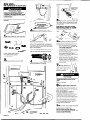
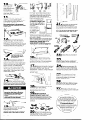
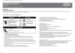
IMPORTANT:
Read and save
these instructions.
Installer:
Leave Installation Instructions
with the homeowner.
Homeowner:
Keep Installation Instructions
for future reference.
electrical
inspector’
Pat-t No. 3389591
Large Capacity Thin Twin
Washer l Dryer
Four-wire 240 Volt
Before you start...
Check location where washer/dryer
will be installed. Proper installation is
your responsibility. The dryer must not
be installed or stored in an area
where it will be exposed to water
and/or weather. Make sure you
have everything
necessary for
correct installation.
Important:
Observe all
governing
codes
and ordinances.
Check code requirements:
Some codes
limit or do not permit installation of
clothes dryers in garages, closets, mobile
homes and sleeping quarters. (Contact
your local building inspector.)
Hot and cold water faucets:
Must be within 4 feet of the back
of the washer/dryer
and provide
water pressure of 5-100 PSI.
Grounded electrical
outlet is
required. See “Electrical
requirements.”
Untape and
open washer
lid. Remove
packages and
hoses from
washer.
Standpipe drain system:
Needs a two-inch diameter
standpipe
with minimum
carry-away
capacity
of 17
gallons per minute. Top of
standpipe
must be at le
inches high and no
higher than 72 inches
from floor.
SEE RECESSED
AREA
INSTRUCTIONS
ON PANEL G.
Dryer may be
exhausted
from the rear
or left or right
side. Exhausting
through the side
requires Part. No.
3391335. (See
“Exhaust requir
Panel B.)
If a longer drain hose is
needed, drain hose
(Part No. 388423) and
hose extension kit (Part
No. 285442) are
available from
Whirlpool-authorized
parts distributors.
Check utilities: Proper
water and electric
supply connections
must be available,
level floor: 1-inch
maximum slope
under entire
washer/dryer.
Support: Floor must be sturdy enough to
supper? washer/dryer
weight, with water
and clothes, of 500 pounds.
Four-inch metal exhaust
duct is required.
Electrical requhements
Fire Hazard
For your safety, the information
in this
manual must be followed to minimize
the risk of fire or explosion or to
prevent property damage, personal
injury or loss of life.
- Do Not store or use gasoline or other
flammable
vapors and liquids in the
vicinity of this or any other
appliance.
- Never install washer/dryer
up
against draperies or curtains or on
carpet.
- Keep any and all items from falling
or collecting
behind the
washer/dryer.
- Replace all access panels before
operating washer/dryer.
Failure to follow these instructions
could result in a fire, explosion or
electrical
shock.
Tools and materials
needed for
installation:
adjustable
wrench (two
Electrical Shock Hazard
Electrical ground is required on this
appliance.
l
If cold water pipe is interrupted
by
plastic, non-metallic
gaskets, or
other insulating materials, Do Not
use for grounding.
l
Do Not ground to a gas pipe.
l
Do Not modify the power supply
cord plug. If it will not fit the outlet,
have a proper outlet installed by a
qualified electrician.
. Use a new 30-ampere
power supply
cord kit. Do Not reuse an old power
supply cord. Possible electrical
shock or fire hazard could occur if
old power supply cord is used.
l
Do Not have a fuse in the neutral or
grounding
circuit. A fuse in the
neutral or grounding
circuit could
result in an electrical
shock.
l
Do Not use an extension cord with
this appliance.
l
Check with a qualified electrician
as to whether the appliance
is
properly grounded.
Failure to follow these instructions
could result in serious injury or death.
l
If codes permit and a separate
wire is used, it is recommended
qualified electrician
determine
grounding
path is adequate.
4
grounding
that a
that the
1 n A three-wire, single-phase,
120/240-volt, 60-Hz, AC-only electrical
supply with a fourth wire as a grounding
wire (or three-wire,
120/208-volt electrical
supply with a fourth wire as a grounding
wire if specified on serial/rating
plate) is
required on a separate 30-ampere
circuit, fused on both sides of the line. The
fourth (grounding)
conductor
must be
identified by a green or green/yellow
cover and the neutral conductor
by a
white cover. Time-delay fuse or circuit
breaker is recommended).
The
serial/rating
plate is located in the door
well behind the dryer door on the front of
the opening.
Panel A
laundry tub drain
system: Needs a 20gallon laundry tub. Top
of tub must be at least
34 inches high and no
higher than 72 inches
from floor.
Location: Should be
large enough to fully
open dryer door to 90”.
(See “Recessed and
closet installation
instructions” and
“Product dimensions,”
Panel G.)
Floor drain system:
Requires a siphon
break, Part No. 285320,
available from a
Whirlpool-authorized
parts distributor,
Phillips screwdriver
Water heater: Set to
deliver 140°F water to
the washer.
Product Damage
Do Not store or operate washer/dryer
below 32°F (some water may remain
in washer). Proper operation of dryer
cycles requires temperatures
above
45°F. See Use & Care Guide for
“Winterizing”
information.
Failure to do
so may result in damage from
freezing.
2
3/4”, U.L.-listed
n This
washer/dryer
is
equipped
with a
30-amp-rated,
fourwire, flexible-type,
power supply cord
(pigtail) and a 3/4”,
U-L.-listed strain
relief. (See Figure
Figure 1
1,) Where local
codes permit, it
must be plugged into a mating, 30-amp
receptacle
(NEMA Type 14-3OR). (See
Figure 2,)
(14-30R) 4-wire
receptacle
Figure 2
Typical JO-amp
receptacle;
use where
local codes permit
flexible-type
power
supply cord (pigtail).
3
n IF THE POWER SUPPLY CORD IS
REMOVED, THE WASHER/DRYER MUST BE
CONNECTED WITH lo-GAUGE MINIMUM
COPPER WIRE ONLY. See “Alternate
electrical connection,”
Panels E and F,
for detailed instructions.
4
n The power supply cord (pigtail)
can be removed and the appliance
can be connected
directly to an
individual, 30-ampere fuse or circuit
breaker box through flexible armored or
non-metallic
sheathed
1O-gaugeminimum copper cable. It is the
personal responsibility and obligation
of
the customer to contact a qualified
electrician
to assure that the electrical
installation is adequate
and is in
conformance
with National Electrical
Code ANSI/NFPA 70-latest
edition and
all local codes and ordinances.
Allow
slack in the line between the wall and
the appliance
so that it can be moved
if servicing is ever necessary. A 3/4” U.L.listed strain relief must be provided at
each end of the power supply cable (at
the appliance
and at the junction box).
5
W If you must
change to a threewire, single-phase,
120/240-volt, 60-Hz,
AC-only, electrical
supply system, and
local codes permit,
a U.L.-listed,
120/240-v0lt
minimum, 30ampere, dryer
Figure 3
power supply cord
kit with a receptacle
of NEMA Type lo30R may be used. (See Figure 3.) This
cord must contain three, No.-1 0 copper
conductors
with ring terminals or spade
terminals with upturned ends on the
washer/dryer
end. Where local codes
permit, it must be plugged into a mating
30-ampere receptacle
(NEMA Type 1O30R). Cord should be Type SRD or SRDT
and be at least four feet long. The
three-wire power supply cord is not
provided with the washer/dryer.
A kit,
Part No. 687104, is available from your
Whirlpool dealer.
NOTE: If local codes require
permanently
connected
wiring, see
“Alternate electrical connection,”
Panels E and F.
To convert to three-wire electrical
system, the four-wire power supply cord
must be removed and the appliance
cabinet must be grounded
according
to local codes either by using the
neutral terminal or a separate
grounding
wire. (See “Alternate
electrical connection,”
Panels E and F
for detailed instructions).
Exhaust reaufrements
*
Fire/Health Hazard
Do Not use non-metal,
flexible duct.
l
Do Not use metal duct smaller than
four inches in diameter.
l
Do Not use exhaust hoods with
magnetic latches.
. Check that exhaust system is not
longer than specified. Exhaust
systems longer than specified will:
- Accumulate
lint.
- Shorten the life of the dryer.
- Reduce performance,
resulting in
longer drying times and
increased energy usage.
Failure to follow specifications
may
result in a fire.
l
Do Not exhaust dryer into a
chimney, furnace cold air duct,
attic or crawl space, or any other
duct used for venting.
. Clean the exhaust system every
other year.
l
Do Not install flexible duct in
enclosed walls, ceilings or floors.
Accumulated
lint could result in a fire
or cause moisture damage.
l
. Exhausting your dryer indoors is not
recommended.
The moisture and
lint indoors may cause:
- FIRE HAZARD from lint collected
in
dryer.
- Moisture damage to woodwork,
furniture, paint, wallpaper,
carpet,
etc.
- Housecleaning
problems and
possible health problems.
Failure to follow these instructions
could result in fire damage or
personal injury.
Panel B
For exhaust systems not covered by the
exhaust length chart, see Whirlpool
Service Manual, Exhaustina Whirlpool
Drvers, Part No. 603197, available from
your Whirlpool parts distributor.
Four-inch rigid
metal pipe is
preferred. Plan
installation to
use the fewest
number of
exhaust
Service check: The back pressure in any
exhaust system used must not exceed
0.6 inches of water column measured
with an incline manometer
at the point
that the exhaust duct connects to the
dryer.
air flow
exhaust
air flow
Metal flexible duct should be fully
extended
and supported when the
dryer is in its final position. DO NOT KINK
OR CRUSH THE DUCT. The metal flexible
duct must be completely
open to allow
adequate
exhaust air to flow.
Allow as much room as possible when
using elbows or making turns. Bend duct
gradually to avoid kinking. Remove
excess flexible duct to avoid sagging
and kinking that may
result in reduced air flow.
The exhaust duct can be
routed up, down, left,
right or straight out the
back of the
washer/dryer.
Space
requirements
are
provided on Panel G of
the Installation
Instructions and on the
rear panel of the washer/dryer.
Maximum length of the exhaust system
depends upon the type of duct used,
number of elbows and the type of
exhaust hood. The maximum length for
both rigid and flexible duct is shown in
the chart
I
i-l/i,,
Rear, Side or Bottom Exhaust
Number
of 90”
Turns
0
1
2
0
:
42 FT.
34 FT.
26 FT.
26 FT.
21 FT.
16 FT.
MAXIMUM
LENGTH OF
4” DIA. RIGID
METAL DUCT
MAXIMUM
LENGTH OF
4” DIA. FLEXIBLE
METAL DUCT
Exhausting the dryer outside is
recommended.
A closet installation
must be exhausted outside. Recessed
installation that is not exhausted outside
must use Exhaust Deflector Pat-t No.
694609 available from your Whirlpool
dealer. See “Recessed and closet
installation instructions,” Panel G, for
adequate,
unobstructed
air opening
requirements.
If the washer/dryer
is installed in a
confined area such as a bedroom,
bathroom or closet, it must be
exhausted to the outside and provision
must be made for enough air for
combustion
and ventilation.
Check
governing codes and ordinances.
Also
refer to “Recessed and closet installation
instructions,” Panel G.
An exhaust hood
should cap the
exhaust duct to
prevent exhausted air
from returning into
dryer. The outlet of the
--lb
hood must be at least
12 inches from the ground or any object
that may be in the path of the exhaust.
Four-inch outlet hood is preferred.
However, a 2-l/2-inch
outlet exhaust
hood may be used. A 2-l/2-inch
outlet
creates greater back pressure than
other hood types.
Exhausting the dryer
through the side of the
washer/dryer
requires
the use of Side Exhaust
Kit, Part No. 3391335.
Follow kit installation
instructions for proper
exhaust installation.
Mobile
home
\
installation
This appliance
is suitable for mobile
home installation. The installation of the
washer/dryer
must conform to the
Manufactured
Home Construction
and
Safety, Title 24 CFR, Part 3280 (formerly
the Federal Standard for Mobile Homes
Construction
and Safety, Title 24, HUD
Part 280, latest edition).
Mobile home exhaust requirements:
The
washer/dryer
must have an outside
exhaust. If the dryer is exhausted
through the floor and the area under
the mobile home is enclosed, the
exhaust system must terminate outside
the enclosed area. Extension beyond
the enclosure will prevent lint and
moisture build-up under the mobile
home.
Now start...
With washer/dryer
in laundry
area.
7
--7l!let
valves are
plastic. Do not
crossthread.
Personal Injury Hazard
More than one person is required to
lift, tilt or move the washer/dryer
because of its weight and size. Failure
to follow this instruction may result in
personal injury.
Truck only from rear to prevent
damage.
I
:
5
product
n Attach hose to bottom inlet valve
opening first; then second hose to top
inlet valve. Tighten couplings by hand.
Then use pliers to make an additional
two-thirds turn.
IMPORTANT: THIS PROCEDURE
MUST BE FOLLOWED TO ASSURE
PROPER INSTALLATION.
n Pull to completely
remove the
shipping strap with 2 cotterpins from the
inside of the washer/dryer.
I
I
1
n Open washer lid. Take hoses and
parts packages out of basket. Close lid.
Pull firmly to remove the
other end of the shipping strap from the
back of the washer/dryer.
The shipping
strap plug must be completely
removed
from the washer/dryer
for the self-leveling
legs to be released.
Save the shipping strap for use in Step 15.
1 hose clamp
4 flat, water-hose
washers
l 4 cable-bracket
screws
0 1 small clamp
l
Use new hose and washers
with your washer/dryer.
that came
l
2
n i?emcve
Check
pa,x
frorr, pacitage
that all parts were included.
4
coupling
6
n TO prevent the drain hose from
coming off or leaking, it must be
installed per the following instructions:
1. Wet the inside end of the drain
hose with tap water. DO NOT USE
ANY OTHER LUBRICANT.
2. Squeeze ears of clamp with pliers
to open and place clamp over the
end of the drain hose.
3. While holding clamp open, work
end of drain hose onto drain
connector
until drain hose is within
l/4 inch of ribbed stop.
4. When the end of the drain hose is
within l/4 inch of ribbed stop,
position clamp on drain hose so
iflOT
wosher
n Insert a flat washer into each end
of the inlet hoses. Check that washers
are firmly seated in couplings.
P
tne oor;om
of tne clamp
1s l/4
inch from the end of the hose,
release pliers.
7
mOpen clamp and
slide over “hook” end of
drain hose to secure the
rigid and corrugated
sections together.
8.
16.
24.
Numbers
correspond
to steps.
Floor Damage
Slide washer/dryer
onto cardboard
or
hardboard
before moving across
floor.
Failure to do so may cause damage
to floor covering.
n If YOU have room to work from
8
either side of the washer/dryer,
move
washer/dryer
close to final position so
you can easily complete
the following
steps. (Go to Step 9.)
If you are working in a closet or
recessed area, move the washer/dryer
into its final position and remove
cardboard
or hardboard
from under
washer/dryer.
Remove the access
panel by removing three Phillips-head
screws and one bumper, located at the
top of the access panel. Set panel,
screws and bumper aside. (See Step
16.) Complete the following steps
through the access area.
9
n Put “hook” end of drain hose into
laundry tub or standpipe.
Check for
proper length of drain hose.
DO NOT FORCE EXCESS LENGTH OF
DRAIN HOSE DOWN THE STANDPIPE. THIS
COULD CAUSE SIPHONING.
Panel C
B
0
A
IO I
n Before
attaching
water
inlet hoses, run
water through both
faucets into a
bucket. This will get
rid of particles in
water lines that might
clog hoses. Mark
which is the hot water faucet.
11
WAttach bottom hose (inlet
marked “H”) to hot water faucet.
Attach top hose (inlet marked ‘C”) to
cold water faucet. Tighten the coupling
to the faucet by hand. Use pliers to
make final two-thirds turn.
Move washer/dryer
to its permanent
location. Remove cardboard
from under
washer/dryer.
P
stiap
strbp
strbp
Put “hook” end of drain hose in tub or
standpipe.
Tightly wrap the shipping
strap around the drain hose and tub or
standpipe
or inlet hose as shown in
Figures A-C. Push plug into the nearest
hole in the shipping strap.
If drain hose cannot be
strapped in place, it must be
cut exactly to length so the
“hook” end is held tightly
over the edge of the tub or
standpipe.
If a longer drain
hose is needed,
drain hose (Part
No. 388423) and
hose extension
kit (Part No.
285442) are
available from a
Whirlpool-authorized
parts distributors. If
drain hose must be shortened, use hose
kit (Part No. 285442).
Note: If washer/dryer
is moved to adjust
drain hose, the washer/dryer
must be
leveled again. Repeat Steps 12- 14.
Place cardboard
under the
washer/dryer
and carefully move
washer/dryer
to avoid damaging
floor
covering.
ML
12
n Tilt washer/drver
forward
raising back legs 1 inch ‘off of floor to
adjust rear, self-leveling
legs. Gently
lower washer/dryer
to floor. Check
levelness of the washer/dryer
by placing
a carpenter’s
level on top of the washer,
first side to side; then front to back. If
washer/dryer
is level, go to Step 14.
’
,
13
Insert corner posts 6 inches
from lefi leg. Do Not insert
corner PO.& in the center of
the washer/dryer.
n If it is not level, carefullv tilt
washer/dryer
backward.until
front of
washer/dryer
is 3-4 inches off of floor.
Insert 4 corner posts under washer/dryer
about 6 inches from the left leg. Loosen
nuts on each front leg. Adjust the front
legs up or down. Tilt washer/dryer
backward
and remove corner posts.
Gently lower the washer/dryer
to the
floor. Repeat Step 12. If it is still not level,
repeat Step 13 and then Step 12 until
washer/dryer
is level.
14
is level,
use wrench to turn nuts on front legs up”
tightly against washer/dryer
base. If nuts
are not tight against washer/dryer
base,
the washer/dryer
may vibrate.
III
16
17
n Determine
the lenath of exhaust
duct that is needed to con&t
the dryer
to the exhaust hood. (See “Exhaust
requirements,”
Panel B.) Connect exhaust
duct to the washer/dryer
and then to the
exhaust hood.
0
18
Phillips screwdriver
adjustable
wrench (tw
I
n If vou did not remove the
access panel in Step 8, remove three
Phillips-head screws and one bumper,
located at the top of the access panel.
Set the panel, screws and bumper
aside.
n When washer/drver
Property Damage
Secure the drain hose to the tub or
standpipe with the shipping strap
removed from the back of the
washer.
Failure to properly secure drain hose
could result in water damage.
I
21
n Check that you removed all
the shipping pieces including the
shipping strap with its 2 cotterpins and
plug. Dispose of all materials in proper
manner.
If you do not remove the shipping strap,
your washer/dryer
may “walk” away
from its location.
/’
/YIP4
n Use duct tape to seal all ioints
’
in exhaust duct. Use caulking
compound
to seal exterior wall opening
around exhaust duct hood.
your tools
23
WTurn on water faucets and
check for leaks. Tighten couplings if
there is leaking. Do Not overtighten;
this
could cause damage to faucet.
24
n Replace access panel. Be
sure to tighten the three Phillips-head
screws at the top of the access panel.
Replace the bumper under the center
screw.
Guide to fully
washer/dryer.
to be sure lint
position. Wipe
understand
your new
Open dryer door. Check
screen is in its proper
out drum.
grounded
outlet. Now start the washer
and allow it to complete
the regular
cycle.
27
WStart dryer and allow it to
complete
a full heat cycle to make sure
it is working properly.
19
n CHECK ELECTRICAL
REQUIREMENTS. BE SURE YOU HAVE
CORRECT ELECTRICAL SUPPLY AND
RECOMMENDED GROUNDING METHOD.
Check the Installation Instructions to see
that you have completed
each step.
Complete
any missed steps before you
continue.
successfully installed your
new, Whirlpool washer/dryer.
your new washer/dryer,
read your
Whirlpool Use and Care Guide.
Congratulations!
Keep Installation Instructions nearby
where you can refer to them.
They’ll make reinstalling your
Whirlpool washer/dryer
in
another home as easy as
the first installation.
n Measure and mark a point
approximately
15 inches from the plug
end of the shipping strap. Cut the
shipping strap at this point.
Check
kinked
that hose is not twisted or
and is securely in place.
Panel D
n Check that all parts are now
installed. (See parts list, Panel C.) If there
is an extra part, go back through steps
to see which step was skipped.
I
Alternate electrical
connection
To convert to a
three-wire
electrical system
When local codes...
Electrical Shock Hazard
Electrical ground is required on this
appliance.
l
If cold water pipe is interrupted
by
plastic, non-metallic
gaskets or
other insulating materials, Do Not
use for grounding.
l
Do Not ground to a gas pipe.
l
Do Not modify the power supply
cord plug. If it will not fit the outlet,
have a proper outlet installed by a
qualified electrician.
l
Use a new 30-ampere
power supply
cord kit. Do Not reuse an old power
supply cord. Possible electrical
shock or fire hazard could occur if
old power supply cord is used.
l
Do Not have a fuse in the neutral or
grounding
circuit. A fuse in the
neutral or grounding circuit could
result in an electrical
shock.
l
Do Not use an extension cord with
this appliance.
. Check with a qualified electrician
as to whether the appliance
is
properly grounded.
Failure to follow these instructions
could result in serious injury or death.
A
n Permit use of a flexible-type
power supply cord (pigtail) plugged into
a matching,
30-ampere receptacle
(See “Electrical requirements,”
Panels A
and B) and
Permit connection
of the internal
grounding
conductor
to the neutral wire
of the power supply cord:
l
Internal
This appliance
is manufactured
with a 30-ampere-rated,
fourwire, flexible-type
power supply
cord with the green grounding wire
connected
to the grounding
connector.
When local codes...
Do Not Permit the use of the flexible
four-wire power supply cord that comes
equipped
with the washer/dryer
and
Permit four-wire copper power supply
cable and
Permit connecting
cabinet-grounding
conductor
to the neutral wire of the
power supply cable:
Center silver-colored
terminal block screw
Internal grounding
wire (green with
Power supply cable grounding
wire (bare copper, green or
green with YellOW StripeS)
grounding
External
connector
Four-wire
ungrounded
neutral
Figure 4
1. Disconnect the power supply.
2. Remove the power cord equipped
with the washer/dryer
as instructed,
See “To remove power supply cord,”
Panel F.
3. Install copper four-wire power supply
cable through the 3/4”, U-L.-listed
strain relief. (See “Electrical
requirements,”
Panels A and B.)
4. Connect the grounding
wire (bare
copper, green or green with yellow
stripes) of the copper, four-wire
power supply cable to the external
grounding
connector.
5. Connect the neutral wire (white) of
the power supply cable and internal
grounding
wire (green with yellow
stripes) to the center, silver-colored,
terminal screw of the terminal block.
Connect the other wires to the outer
terminals. Tighten each screw firmly.
See Figure 4. For plain-end wires, see
“Direct wiring connection,”
Panel F.
6. Replace the terminal block cover.
Panel E
When local codes...
B
n Permit the use of a flexible-tvpe
’’
power supply cord (pigtail) but
Do Not Permit connecting
cabinetgrounding
conductor
to the neutral wire
of the power supply cord:
Internal grounding
wire (green with
yellow stripes)
/
Center silver-colored
terminal block screw
and neutral white wire
\
Center silver-colored
terminal block screw
wire
grounding
External
Ungrounded
grounding
neutral
Figure 6
Grounded
neutral
Figure 5
1. Disconnect the power supply.
2. Remove the power supply cord
equipped
with the washer/dryer
as
instructed. See “To remove the power
supply cord,” Panel F.
3. Install a three-wire power supply cord
(see “Electrical requirements,”
Panels
A and B) through the 3/4”, U.L.-listed
strain relief.
4. Move the internal grounding
wire
(green with yellow stripes) from the
center, silver-colored
terminal block
screw to the external grounding
connector.
5. Connect the neutral wire (white) of
the power supply cord to the center,
silver-colored,
terminal screw of the
terminal block. Connect the other
wires to the outer terminals. Tighten
each screw firmly. See Figure 5. For
plain-end wires, see “Direct wiring
connection,”
Panel F.
6. Replace the terminal block cover.
Connect separate, copper grounding
wire (No.- 10 minimum) from external
grounding
connector
to approved
ground.
1. Disconnect the power supply.
2. Remove the power supply cord
equipped
with the washer/dryer
as
instructed. See “To remove the power
supply cord,” Panel F.
3. Install a three-wire power supply cord
(See “Electrical requirements,”
Panels
A and B) through the 3/4”, U.L.-listed
strain relief.
4. Connect the neutral wire (white) of
the power supply cord and the
internal grounding
wire (green with
yellow stripes) to the center, silvercolored, terminal screw of the
terminal block. Connect the other
wires to the outer terminals. Tighten
screws firmly. (See Figure 6.) For plainend wires, see “Direct wiring
connection,”
Panel F.
5. Connect a separate copper
grounding
wire (No. 10 minimum>.
See “To connect a separate
grounding
wire,” Panel F, for detailed
instructions.
6. Replace the terminal block cover.
When local codes...
When local codes...
C
w Do Not Permit the use of a
flexible, three-wire, power supply cord
and
Permit three-wire, copper power supply
cable and
Permit connecting
the cabinetgrounding
conductor
to the neutral wire
of the power supply cable:
Internal grounding
wire (green with
yellow stripes)
Center silver-colored
terminal block screw
and neutral white wire
To connect
grounding
D
a separate
wire -
n Do Not Permit the use of a
flexible, three-wire, power supply cord
and
Permit three-wire, copper power supply
cable but
Do Not Permit connecting
the cabinetgrounding
conductor
to the neutral wire
of the power supply cable:
Internal grounding
wire (green with
yellow stripes)
Center silver-colored
terminal block screw
and neutral white wire
Use grounding
wire and clamp
assembly (Part No. 685463) or No.
1O-gauge minimum copper grounding
wire.
0.4
ire
’
Grounded
External grounding
connector
Figure 10
neutral
Ungrounded
Figure 7
neutral
Figure 8
1. Disconnect the power supply cord.
2. Remove the power supply cord
equipped
with the washer/dryer
as
instructed. See “To remove the power
supply cord,” Panel F.
3. Install copper power supply cable
(See “Electrical requirements,”
Panels
A and B) through the 3/4”, U.L.-listed
strain relief.
4. Move the internal grounding
wire
.
(green with yellow stripes) from the
center, silver-colored,
terminal block
screw to the external grounding
connector.
5. Connect the neutral wire (white) of
the fleixlbe, armored or non-metallic
sheathed, copper, power supply
cable to the center, silver-colored,
terminal screw of the terminal block.
Connect the other wires to the outer
terminals. Tighten the screws firmly.
See Figure 7. For plain-end wires, see
“Direct wiring connection,”
Panel F.
6. Replace the terminal block cover,
To remove the
power supply
cord -
1. Disconnect the power supply.
2. Remove the power supply cord
equipped
with the washer/dryer
as
instructed. See “To remove the power
supply cord,” Panel F.
3. Install copper power supply cable
(See “Electrical requirements,”
Panels
A and B) through the 3/4”, U.L.-listed
strain relief,
4. Connect the neutral wire (white) of
the flexible, armored or non-metallic
sheathed, copper power supply
cable and the internal grounding
wire (green with yellow stripes) to the
center, silver-colored
terminal screw
of the termianl block.
Connect the other wires to the outer
terminals. Tighten screws firmly. (See
Figure 8.) For plain-end wires, see
“Direct wiring connection,”
Panel F.
5. Connect a separate copper
grounding
wire (No.-1 0 minimum).
See “To connect a separate
grounding
wire,” Panel F, for detailed
instructions.
6. Replace the terminal block cover
\
1. Disconnect the
power supply.
2. Remove the
terminal block cover
from the dryer.
3. Disconnect
the
power supply cord
from the terminal
block.
4. Disconnect the
green, grounding
wire of the power
supply cord from the
external grounding
connector.
5. Loosen the strain
relief screws.
5. Pull downward
on
the power supply
cord until it is
removed from the
dryer. See Figure 11,
Panel F
Connect separate, copper grounding
wire (No.- 10 minimum) from external
grounding
connector
to approved
ground.
Connect grounding
wire to a grounded
cold-water
pipe* with the clamp and
then to the external grounding
connector
on the washer/dryer.
(See
Figure 4.) Do Not ground to a gas supply
pipe or hot-water pipe. Do Not connect
the power supply cord to electric power
supply until the appliance
is
permanently
grounded.
l
Grounded
cold-water
pipe must have
metal continuity to electrical
ground and
not be interrupted
by plastic, rubber or
other electrical
insulating connectors
such
as hoses, fittings, washers or gaskets
(including water meter or pump). Any
electrical
insulating connector
should be
jumped as shown in Figure 10 with a length
of No.-4 wire securely clamped
to bare
metal at both ends.
Direct wiring connection
0
1. Disconnect the power supply.
2. Strip the outer covering back 3
inches from the end, exposing the
three wires.
/
Plain-end
wiring
Figure 12
3. Strip the insulation back 1 inch from
the end of each wire. Form the bare
wires into a “U-shaped
hook.
4. Loosen, Do Not remove, screws from
terminal block. Attach wires
according
to instructions for type of
connection
needed.
5. Slide the end of each wire under the
screw head with the open side of the
screw hook on the right. Squeeze the
wire together to form a loop.
6. Tighten each screw firmly.
7. Tighten strain relief screws.
Recessed and closet
installation instructions
Product
Recessed
area minimum
Fire Hazard
It is recommended
that the dryer be
exhausted outside
l
If washer/dryer
is installed in a
closet, the dryer MUST be exhausted
outside.
Failure to do so may cause a fire.
installation
spacing
dimensions
1+26-l/4’
a- 3”
l
This washer/dryer
may be installed in a
recessed area or closet.
The installation spacing is in inches and
is minimum allowable.
Additional
spacing should be considered
for ease
of installation, servicing and compliance
with local codes and ordinances.
If closet door is installed, the minimum
unobstructed
air openings in top and
bottom are required. Louvered doors
with equivalent
air openings are
acceptable.
Closet installation must be
exhausted.
Other installations must use the minimum
dimensions indicated.
TO PREVENT LARGE AMOUNTS OF LINT
AND MOISTURE FROM ACCUMULATING,
TO MAINTAIN DRYING EFFICIENCY, THIS
APPLIANCE SHOULD BE EXHAUSTED
OUTDOORS.
Washer
I
•I .
Side View
J
Front View
+27-3/a”
Recessed, non-exhausted
installation
must use only the rear exhaust position
and Exhaust Deflector Part No. 694609.
Note: If recessed installation is
exhausted to the side or rear, 6 inches
must be available above the
washer/dryer
but all other spacing can
be 0 inches.
Closet installation
must be exhausted
Closet
-i
outdoors.
Door
46”
/
f
48. sq. in. +*
4
1” min.+
24. sq. in. *
l
Side View
Closet
Door
sq. in. *
l
sq. in. *
l
4
*
Front View
Additional
clearances
for wall, door and floor
moldings may be required or if external
exhaust elbow is used.
** Opening is minimum for closet door, Louvered
door with equivalent
air openings is
acceptable.
*** $MiEnal
space may be needed for exhaust
Panel G
-
+I
If washer/dryer
not operate
properly.. .
does
Check the following to be sure that:
1, Electric supply is connected.
2. House fuse or circuit breaker is intact
and tight.
3. Washer lid or dryer door is closed.
4. Controls are set in a running or “ON”
position.
5. Dryer start button has been firmly
pushed.
6. Make sure shipping strap has been
completely
removed and was used to
secure the drain hose to the tub or
standpipe.
If you need service...
If you need
assistance...
The Whirlpool Consumer Assistance
Center will answer any questions about
operating
or maintaining
your
washer/dryer
not covered in the
Installation Instructions. The Whirlpool
Consumer Assistance Center is open 24
hours a day, 7 days a week. Just dial
1-800-253-l 30 1 - the call is free.
When you call, you will need the
washer/dryer
model number and serial
number. Both numbers can be found on
the serial/rating
plate located in the
door well behind the dryer door and on
front of opening.
When moving the
washer/dryer.. .
l
l
l
In the event that your Whirlpool
appliance
should need service, call the
dealer from whom you purchased
the
appliance
or a Whirlpool-authorized
service company.
A Whirlpoolauthorized service company
is listed in
the Yellow Pages of your telephone
directory under “Appliances
Household - Major - Service or
Repair.” You can also obtain the service
company’s
name and telephone
number by dialing, free, within the
continental
United States, the Whirlpool
Consumer Assistance Center telephone
number, 1-800-253-l 301. A special
operator will tell you the name and
number of your nearest Whirlpoolauthorized service company.
Maintain the quality built into your
Whirlpool appliance
- call a Whirlpoolauthorized service company.
Disconnect
the power supply cord,
then tape securely to the
washer/dryer.
Tape the drum to the front panel.
Tape the lint screen in place. Tape
the dryer door closed.
Wedge a blanket between the tub
ring and cabinet top to restrict tub
movement.
Part No. 3389591
01992 Whirlpool Corporation
Prepared
by Whirlpool
Corporation,
Benton
Harbor, Michigan
49022
Printed in U.S.A.