1
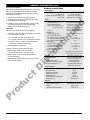
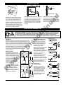
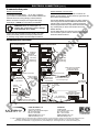
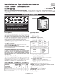
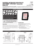
Autostart AS731/AS732 Generator Controller
Installation Instructions
mi6128
th
revision G, 10 Sept 2007
catalogue section 75
Section A: Panel Installation and Wiring
Please read the following information before installing. A visual inspection of this product for damage during
shipping is recommended before installation. It is your responsibility to ensure that qualified mechanical and electrical
technicians install this product. If in doubt, please contact your local Murphy representative.
W A R N IN G
Front facia
BEFORE BEGINNING INSTALLATION OF THIS MURPHY PRODUCT
nt
i
Disconnect all electrical power to the machine
Make sure the machine cannot operate during installation
Follow all safety warnings of the machine manufacturer
Read and follow all installation instructions
nu
ed
GENERAL INFORMATION
co
General
1. 2 line x 16 character backlit liquid crystal display
2. Operator control keys
3. Auto/manual mode LED indication
is
The Autostart AS731 and AS732 provide full-function,
automatic or manual control for diesel generators.
The fully programmable, microprocessor-based units
include full measurement and display of engine and AC
generator parameters, with a fully automatic fault protection
and warning system. Facilities are also provided for remote
monitoring and control via RS232 communication link and
PC software; the AS732 additionally features an RS485
MODBUS RTU compatible link.
This document details the panel mounting and electrical
connection of AS731 and AS732 units fitted with firmware
versions V1.00 through V2.x.x. Further details about
specification, programming and operation may be found
in the following documents:-
ct
D
Rear facia
Title
ms6127
ms6343
mi6129
mi6243
AS731 bulletin
AS732 bulletin
AS731/732 installation B: programming
AS731/732 installation C:
AS730 to AS731/AS732 retrofitting
AS731/732 operation
AS731/732 and PC software model AS7CN
AS732 RS485 MODBUS protocol
du
Doc. ref.
ro
mi6130
mi6131
mi6344
P
MODBUS® is a registered trademark of AEG Schneider Automation Inc.
4.
5.
6.
7.
FRANK W. MURPHY LTD.
Church Rd, Laverstock,
Salisbury, SP1 1QZ, United Kingdom
tel: +44 1722 410055
fax: +44 1722 410088
email: sales@fwmurphy.co.uk
web: www.fwmurphy.co.uk
Mounting clamps
2 x two part, screw terminal blocks, 1 – 20 and 21 - 30
RS232 communication port (RJ11 connector)
(AS732 only) RS485 comms ports (2 x RJ45 connectors)
FW MURPHY
PO Box 470248
Tulsa, Oklahoma 74147, USA
tel: +1 918 317 4100
fax: +1 918 317 4266
email: sales@fwmurphy.com
web: www.fwmurphy.com
In order to consistently bring you the highest quality, full featured products, we reserve the right to change our specifications and designs at any time.
MURPHY, the Murphy logo, are registered and/or common law trademarks of Murphy Industries, Inc. This document, including
textual matter and illustrations, is copyright protected by Frank W Murphy Ltd., with all rights reserved. © 2007 Frank W Murphy Ltd.
GENERAL INFORMATION (cont.)
Anti-static precautions
Product specification
The AS731/732 features sensitive electronic components
that may be damaged by static discharge. Anti-static
precautions must therefore be observed when storing,
unpacking and handling:-
Power supply:
Operating voltage: steady state range
crank brown-out
Current consumption: standby (typ)
cranking (typ)
• Store the unit in the anti-static bags supplied
• Use earthed wrist straps and anti-static mats when
• Handle the unit by its external plastic casing. Except
for connection purposes, avoid direct physical
contact with the electrical connectors.
Unpacking
Inputs 3 – 5
Generator AC:operating voltage range
3 phase, 90 – 300 V AC rms L–N
gen. volts display resolution
1 VAC
gen. frequency measurement range
0 – 99 Hz.
gen. frequency display accuracy
<= 2% of full scale
gen. frequency display resolution
1 Hz.
Magnetic pickup:
operating voltage range
2.5 – 25 V AC rms
frequency measurement range
0 – 10 kHz.
engine RPM display accuracy
<= 2% of full scale
engine RPM display resolution
10 RPM
AC current sensing inputs:
operating range
designed for use with 5 Amp CT's
primary ratings 10 to 5000 Amps
For each unit ordered, the following is supplied:-
• 1 x AS731 or AS732 module (model reference as listed
on the rear label), including:¾ 2 x removable terminal blocks at the rear
¾ 2 x mounting clamps (one on each side of the case)
nt
i
¾ on AS732 units, 1 x network terminator module
inserted into one of the RS485 ports.
• These installation instructions
communication lead, RJ11 to 9 way D type.
• Model AS7CQ, 9 way to 25 way D type adaptor,
for use with AS7CP.
ct
positive DC (switched relay)
rated 16 A max. @ 24 V DC
volt free SPNO relay
5 A max. @ 240 V AC
negative DC (semiconductor)
500 mA max. @ 33 V DC
Communications:
RS232 port connector
RS232 Baud rate
RS232 max. lead length
RS485 port connector
RS485 Baud rate
RS485 maximum network length
RS485 protocol
RJ11
9600
10 metres
2 x RJ45
9600
1000 metres
MODBUS RTU
Physical:
Overall dimensions (W x H x D)
Panel cut-out size (W x H)
Weight
Operating ambient temperature
144 x 96 x 162 mm
DIN standard 140 x 92 mm
approx. 770 g
o
–10 to +55 C
P
ro
du
(all ratings for resistive load)
Start and fuel relays
Programmable output 1
(default setting: gen. contactor)
Programmable outputs 2 – 4
D
RJ11 to 25 way D type.
Outputs:
is
• Model AS7CR, RS232 modem communication lead,
co
Optional communication accessories include:-
• Model AS7CP, RS232 local (null modem)
80% to 100% of battery positive
–1V to +2V w.r.t. battery negative
switch (open or closed) or
analogue (Murphy, Datcon, VDO
5 or 7 bar), wired to negative DC
open or closed to negative DC
nu
ed
Inputs:
DC inputs:positive input defined as:
negative input defined as:
Inputs 1 and 2 (oil pressure and
engine temperature)
handling and during installation.
5 – 40 V DC continuous
to 0 V for >=100mS
95mA @ 12V, 55mA @ 24V
280mA @ 12V, 170mA @ 24V
FWMurphy – AS731 / AS732 installation section A: panel installation and wiring
th
mi6128 revision G 10 Sept 2007 p2/6
PANEL MOUNTING
150
2.
1.
30
(typ)
3.
92
FRONT
FRONT
140
D
B
C
nu
ed
(mm)
A
Working behind the panel front, fit the two
mounting clamps to studs on the side of
the case. Locate each clamp on to the
front stud (B), compress the clamp by
pressing on the screw (C) and push the
clamp upwards to locate on to the rear
stud (D).
Each unit is mounted in the front of a
control panel through a DIN standard
cut-out, 140 mm wide by 92 mm high.
With the mounting clamps removed,
insert the module through the front of the
panel cut-out (A). The case extends to
150mm behind the panel front. An extra
30mm should typically be allowed for the
connection of the wiring harness.
With both clamps fitted, tighten the
screwed pins (E) so that they move
forward and secure the unit to the rear
of the panel facia (F). The case design
allows a panel thickness of up to 8mm.
nt
i
ELECTRICAL CONNECTION
co
WARNING: DANGER OF INJURY OR DEATH. During normal operation, the AS731/AS732
is connected to high voltage AC circuits. Before connection, disconnection or handling
DANGER ! of these units, ensure that all AC and DC power supplies are isolated. Connection to
HIGH VOLTS or disconnection from live wiring may also cause damage to AS731/AS732 internal components.
D
is
Electrical connection is at the rear of each unit, through a
pair of two-part type screw terminal blocks labelled 1 - 20
and 21 - 30. Use a 3mm (1/8”) flat head screwdriver to
loosen and tighten each screw terminal: to avoid excessive
rotational force on the circuit boards, Murphy recommend
that each connector block is removed from the unit before
loosening or tightening individual screw terminals.
Murphy make the following general connection
recommendations:-
External Slave Relays are a
recommended connection on
all outputs (as shown right),
either to achieve the required
load switching capability, or
to reduce wear and tear on
internal relay contacts.
Slave relay and solenoid coils
will naturally emit voltage
spikes when de-energising,
with the potential to cause faulty
operation of, or damage to,
electronic equipment.
Suppress relay and solenoid
coils at source, using the
manufacturer’s recommended
suppression network. DC coiled
relays may also be suppressed
using a reversed biased
flywheel diode as shown right.
Control panel
other
controls
charger
+
battery
Control panel
Autostart
other
controls
charger
+
Autostart
RL1
Negative outputs:-
+
Autostart
RL1
AC cabling &
wiring harnesses
P
Minimise the effects of charger
output noise by using separate
wiring 1) between charger
output and battery terminals
(or starter motor star point) and
2) between battery terminals
and panel DC supply rail.
Autostart
+
+
Autostart
ro
du
ct
Battery chargers
Some battery chargers feature
significant ripple and switching
noise on the DC output. This
electrical interference can be
imposed on the panel power
supply and control lines, with
the potential to cause faulty
operation of (and in extreme
cases damage to) electronic
control equipment.
Positive outputs
Separation of AC and DC
wiring/harnesses is strongly
recommended, in particular
where AC circuits feature
inductive/switched loads
or high frequency noise, or
where cable lengths above
5 metres are used.
Autostart
General
battery
FWMurphy – AS731 / AS732 installation section A: panel installation and wiring
th
mi6128 revision G 10 Sept 2007 p3/6
ELECTRICAL CONNECTION (cont.)
Output 1 (pins 7 and 8) is a volt free, normally open
contact (see specification for rating info). The default
program action is set for ‘generator contactor’ control.
A typical wiring diagram is shown in the panel on page 5.
Specific terminal functions are as follows:-
Terminal block 1 - 20
Outputs 2, 3 and 4 (pins 9, 10 and 11) are semiconductor outputs. Each output gives a negative
DC signal when active (maximum rating 500mA),
and is typically used to drive a remote slave relay:
connect the relay coil between the output and
positive DC, and suppress each coil with a flywheel
diode or suitable suppressor network (as detailed
left, and on the typical wiring diagram below).
Negative DC power supply/ground
Positive DC power supply
Use a clean, noise-free DC supply between 5 and 40 V,
normally the engine's 12V or 24V battery supply.
The AS731/AS732 design is optimised for use with
negative ground (earth return) systems, but may also
be used with insulated (two wire) systems. These units
MUST NOT be connected to positive earth systems.
Pin 1 (negative DC) MUST be connected to ground/earth
before connection of the RS232 communication port.
WARNING: failure to connect pin 1 to negative
DC / ground before connecting the RS232 port
may result in damage to the AS731/AS732, PC
or laptop.
The wiring to the positive DC terminal (pin 3) should
incorporate a 5 Amp anti-surge fuse.
12 Input 1: Low Oil Pressure (LOP)
13 Input 2: High Engine Temperature (HET)
14 LOP/HET return/ground
These terminals allow connection of LOP and HET
resistive senders or fault switches. Before use,
the module must be programmed for use with the
specific type of sender (Murphy, Datcon or VDO)
or switch (open on fault or closed on fault).
Resistive senders allow the Autostart to measure
and display oil pressure and temperature. Senders
also enable a pre-alarm warning as well as a
shutdown response. For greatest accuracy and most
reliable operation, two wire senders should be used.
The sender should be connected between each input
and the common return wire on pin 14. One wire
(ground return) senders should not be used, since
small amounts of noise on the ground/chassis can
result in significant signal distortion and
measurement error.
Charge fail input
A 'charge fail' condition occurs when this pin is switched
to negative DC. Pin 2 may be connected to the WL
terminal of a charge alternator (Autostart provides the
necessary excitation current), or to the 'charge fail'
output of a BC700 series charger, or direct to negative
DC via relay contacts which close on fault.
When used with a charge alternator, pin 2 may also be
programmed to detect an ‘engine running’ condition.
If a charge fail alarm is not required, leave pin 2 open
circuit and program the ‘charge fail’ setting to ‘not used’.
is
co
2
Output 2 has default programming ‘common alarm’.
The default setting of outputs 3 and 4 is ‘not used’.
nt
i
1
3
nu
ed
Pin Function
D
Fuel output
Starter output
These are positive DC outputs, rated to 16 Amps, for
the control of engine (energised to run) fuel and starter
motor circuits. Murphy recommend the connection of
slave relays, with suppressed coils, between these
outputs and the fuel and starter solenoids (see typical
connection circuit on previous page).
ro
du
5
6
Positive DC (feed for relays)/Emergency stop
Pin 4 is a positive DC feed for the Fuel and Start outputs
(pins 5 and 6). If required, emergency stop switches
(push to break, mechanically latching types) may be
wired between positive DC and pin 4.
ct
4
Program output (POP) 1a: Normally open contact
Program output (POP)1b – Normally open contact
Program output (POP) 2 – solid state, negative DC
Program output (POP) 3 – solid state, negative DC
Program output (POP) 4 – solid state, negative DC
These outputs may be programmed to give one of 50
signalling and control ‘actions’, e.g. ‘preheat’, ‘engine
running’, ‘overspeed fault’, etc. A full list of output
‘actions’ may be found in document mi6129.
P
7
8
9
10
11
Fault switches allow the trigger of a simple shutdown
response. A two-wire (insulated) switch should be wired
between the input and pin 14. For earth return switches,
leave pin 14 open circuit (to avoid ground loops).
Further details of sender options and characteristics
can be found in the AS731/732 programming
literature, document mi6129.
15 Input 3 (programmable)
16 Input 4 (programmable)
17 Input 5 (programmable)
These inputs may be used with remote contacts
(open or closed to activate) to trigger a range
of programmable ‘actions’, e.g. shutdown fault,
warning fault, lamp test, manual start, manual restore
(of mains supply), etc. (see document mi6129 for full
programming details)
The remote contacts should be wired between the
input and battery negative.
18 Remote start/mains fail input
Use this input to initiate an automatic engine start
in AUTO mode. Connect the remote contact
between pin 18 and battery positive DC. The input
may be programmed to initiate a remote start on
either an opening or closing contact.
FWMurphy – AS731 / AS732 installation section A: panel installation and wiring
th
mi6128 revision G 10 Sept 2007 p4/6
ELECTRICAL CONNECTION (cont.)
the automatic crank release, load switching and
voltage/frequency/speed tripping.
19 Magnetic pickup positive
20 Magnetic pickup negative
These terminals allow engine speed to be measured
using a magnetic pickup. Pickup positive and negative
output terminals should be respectively connected
to pins 19 and 20. (Note: where the pickup head is
isolated from the pickup body and ground, polarity
of connection is not usually important.)
The connection between pickup and Autostart should
use a twisted pair and shield cable, with the shield
connected to ground at one end only.
The number of engine flywheel teeth must be
programmed into the unit before it will correctly
measure and display engine speed.
A 1 Amp anti-surge fuse should be connected in series
with each phase input (pins 21, 22 and 23).
25
26
27
28
29
30
Terminal block 21 - 30
Generator volts L1
Generator volts L2
Generator volts L3
Generator Neutral
CT L1
CT L1 return
CT L2
CT L2 return
CT L3
CT L3 return
These inputs are used to measure 3 phase generator
current. Each input pair is designed for direct
connection to a current transformer (CT) with a 5 Amp
rated secondary coil. Where CTs are connected at a
common star point, the star point should be
commoned with pins 26, 28 and 30.
nt
i
21
22
23
24
nu
ed
Voltages are measured between each phase and the
neutral terminal (maximum rating 300 VAC). The unit
can however be programmed to display AC voltages
as either phase to neutral or phase to phase. Voltages
are displayed on the LCD, left to right, L1, L2, L3.
The AS731/AS732 can also be programmed for use
with 2 phase and neutral systems (leave pin 23 open
circuit) and single phase systems (leave pins 22 ad 23
open circuit).
WARNING: HIGH VOLTAGE DANGER OF INJURY OR DEATH.
co
• Ensure that all AC power supplies are
isolated before connection, disconnection
or handling.
• Use fully shrouded wiring connectors on
these terminals.
is
These terminals are used to sense the generator AC
voltage and frequency, required for functions such as
The CT primary coil ratio must be programmed into
the Autostart before the unit will correctly measure and
display AC current. A number of other programmable
options allow the setting of generator over current
warning and/or trip levels.
Typical wiring diagram (AS731 automatic mains fail generator)
generator
contactor
LOAD
L1L2 L3 N
D
mains
contactor
L1
L2
L3
N
L1 G
L2 E
L3 N
N E
R
A
T
O
R
MCCB
ct
M
A
I
N
S
L1L2 L3 N
MCR1
UVR500
du
MCR
GCR
GCR1
123456
+ve DC
5A
fuse
ro
+
A
RPO2
RPO3
Emerg.
Stop
RPO4
WL
magnetic
pickup
IP5
RST
IP3
starter
RFL
IP4
fuel
LOP
inputs
HET
P
–
Autostart
731 21
1
2
3
4
5
6
7
8
9
10
11
12
13
14
15
16
17
18
19
20
22
23
24
1A
1A
1A
25
26
27
28
29
30
–ve DC
FWMurphy – AS731 / AS732 installation section A: panel installation and wiring
th
mi6128 revision G 10 Sept 2007 p5/6
ELECTRICAL CONNECTION (cont.)
Communication ports
RS232 communication
RS485 MODBUS communication
To the right of terminal block 1 – 30, an RJ11 telephone
type connector enables RS232 communication between the
Autostart and a PC running Murphy software AS7CN.
Model AS732 has two additional RJ45 connectors for
RS485 communications, located at the top right of the rear
facia (above the RS232 port).
WARNING: failure to connect pin 1 to
negative DC / ground may result in damage
to the Autostart, PC or laptop.
Inter-module RS485 communication is by daisy chaining
units using RJ45 terminated 100BaseT Ethernet leads
(CAT5E cable is recommended). A network terminator
module (supplied with each unit) should be inserted into
any unused ports (on those units at either end of the
RS485 network).
nu
ed
Before connection of this port, the negative DC supply
terminal (pin 1) MUST be connected to ground/earth.
For full details about the connection and operation of the
communication systems and PC software, please refer to
document reference mi6131.
The PC may be connected to the port ‘locally’ via a short
serial (null-modem) lead such a Murphy model AS7CP,
or ‘remotely’ using modems and the telephone network.
Communication networks
Generator Site
Modem Communications
AS732
nt
i
Local Communications
AS732
13
RS485 lead
(100BaseT
Ethernet,
RJ45 - RJ45,
CAT5 cable)
AS732
AS732
RS485 ports
(AS732 only)
13
RS485 ports
(AS732 only)
is
13
RS485 lead
(100BaseT
Ethernet,
RJ45 - RJ45,
CAT5 cable)
co
13
AS731/732
RS232 Hayes AT compatible
modem, DC powered
(not supplied by Murphy)
AS731/732
13
D
13
RS232 port (all units)
– +
PC
du
Software
AS7CN
AS7CP null modem
(RS232) lead,
RJ11 - 9 way D type
ct
Negative DC
must be connected
to ground/earth
PC COM port
RS232 port (all units)
– +
Negative DC
must be connected
to ground/earth
Software
AS7CN
PC
Software
AS7CN
PC
ro
AS7CQ
optional 9 way to 25 way adaptor
(for use with 25 way PC COM ports)
P
Generator Site
FRANK W. MURPHY LTD.
Church Rd, Laverstock,
Salisbury, SP1 1QZ, United Kingdom
tel: +44 1722 410055
fax: +44 1722 410088
email: sales@fwmurphy.co.uk
web: www.fwmurphy.co.uk
AS7CR RS232 modem lead,
RJ11 to 25 way D-type
PC with
internal modem
PC with
COM port
Public Switched
Telephone Network
external modem,
RS232 Hayes AT compatible
(not supplied by Murphy)
PC - modem lead
(not supplied by Murphy)
Remote Control Site
FW MURPHY
PO Box 470248
Tulsa, Oklahoma 74147, USA
tel: +1 918 317 4100
fax: +1 918 317 4266
email: sales@fwmurphy.com
web: www.fwmurphy.com
In order to consistently bring you the highest quality, full featured products, we reserve the right to change our specifications and designs at any time.
MURPHY, the Murphy logo, are registered and/or common law trademarks of Murphy Industries, Inc. This document, including
textual matter and illustrations, is copyright protected by Frank W Murphy Ltd., with all rights reserved. © 2007 Frank W Murphy Ltd.
FWMurphy – AS731 / AS732 installation section A: panel installation and wiring
th
mi6128 revision G 10 Sept 2007 p6/6