1
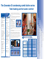
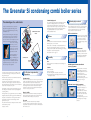
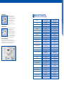
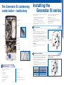
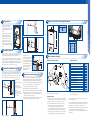
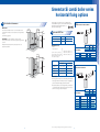
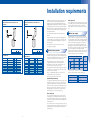
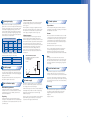
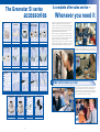
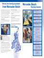
SEDBUK Band A
Gas Boilers
Useful numbers
Sales
Service
Tel: 01905 752640
Fax: 01905 456445
01905 455394
Tel: 08457 256206
Fax: 01905 757536
Livingston (Scotland)
Fax: 01506 441687
Technical (Pre & Post Sales)
Training
Tel: 08705 266241
Fax: 01905 752741
Tel: 01905 752526
Fax: 01905 752535
Spares
Literature Line
Tel: 01905 752571
Fax: 01905 754620
Tel: 01905 752556
The Worcester Bosch
Greenstar Si Gas-fired Condensing
Combi Boiler Series
Technical and Specification Information
Energy Efficiency is an Energy Saving Trust
initiative backed by the Government.
The Council for
Registered Gas
Installers
Worcester, Bosch Group is a trading name of BBT Thermotechnology UK Ltd.
This leaflet is accurate at the date of printing, but may be superseded and should be disregarded if specification and/or appearances are changed
in the interest of continued improvement. The statutory rights of the consumer are not not affected.
Part No. 8 716 108 901
Issue A
WH1387
Worcester, Bosch Group
Cotswold Way, Warndon, Worcester, WR4 9SW
Tel 01905 754624 Fax: 01905 754619 www.worcester-bosch.co.uk
the nation’s favourite for
PLUMBING & HEATING SUPPLIES
FREE SHIPPING
SECURE PAYMENTS
on all orders over £100 to mainland UK
shop online with confidence
FINANCE AVAILABLE
PRICE MATCH
spread the cost with low interest rates
always get the best deals available
we have
H U G E
R E D U C T I O N S
ON THOUSANDS OF ITEMS
Boilers
Bathroom suites
Radiators
Kitchen sinks & taps
Heating controls
Showers
Pipes & ittings
Wet rooms
Cylinders
Towel warmers
Fires
Bathroom furniture
Renewable energy
& much more
visit our website
plumbnation.co.uk
CALL US ON
0844
800
3460
The Greenstar Si condensing combi boiler series
Total heating and hot water comfort
The Greenstar Si combi series
Adjustable hot water
control.
User comfort and
economy.
Aluminium silicon heat
exchanger.
High efficiency.
Boiler keep hot
facility.
Instantly heated hot
water.
SEDBUK Band A.
High efficiency.
Less than 28kg lift
weight.
One man lift.
Wall mounting jig.
Allows pre-fabrication
of system.
Compact dimensions.
Space saving, ease of
siting.
Modulation control.
Energy saving.
Optional filling link.
Labour saving.
Optional mechanical
and digital timeclocks.
Eliminates the need for
external wiring.
Radio frequency
controlled room
thermostat.
Eliminates wiring, helps
comply with part L of
Building Regulations.
Anti-cycle control.
Energy saving.
Electronic ignition.
Energy saving.
Built-in frost protection.
Money saving,
economical protection.
Multi-directional
fluing.
Siting flexibility.
No ventilation grilles
required for
compartment
installations.
Money and labour
saving.
Fault finding
diagnostics.
Time saving.
Operational status
indicator.
Consumer friendly.
Built-in boiler bypass.
Labour and money
saving.
Pump seizure
protection.
Prevents callbacks.
It’s often said that you can’t please everybody all of the time – but
the advanced new series of Greenstar Si condensing combi boilers
from Worcester Bosch has so much to offer that it’s already disproving
such a notion.
Here is a groundbreaking range of energy-saving boilers which is very
good news for the environment and excellent news for specifiers,
developers, installers and consumers alike.
Higher efficiency and highly
COMBUSTION
COMBUSTION
PRODUCTS
PRODUCTS
cost effective
20%
3%
COMBUSTION
Up to an incredible 97% of the
PRODUCTS
gas consumed by a new
80%
Greenstar Si condensing combi
97%
boiler is converted into heat for
the heating and/or hot water
NEW CONVENTIONAL
GREENSTAR
system. Other types of boiler
BOILER
CONDENSING
achieve around 80% efficiency.
BOILER
Therefore, compared with a new
conventional combi boiler, a Greenstar Si can cut heating and hot water
bills by between15-20% – and it’s up to 30% cheaper to run than an
older boiler.
COMBUSTION
PRODUCTS
GROSS
GROSS
30Si
Min
7.2kW
7.2kW
Max
25.0kW
30.0kW
10.2 lt/min
12.3 lt/min
CH temperature control
✓
✓
DHW temperature
control
✓
✓
Modulating control
✓
✓
Natural gas
✓
✓
LPG
✓
✓
Electronic ignition
✓
✓
Output kW
27,140 kWh
924 therms
BASED ON
3 BEDROOM
SEMI-DETACHED
HOUSE
60 - 70%
EFFICIENCY
OLD
EXISTING BOILER
2
OLD
EXISTING
BOILER
23,600 kWh
804 therms
19,588 kWh
667 therms
NEW
GREENSTAR Si IN
CONVENTIONAL CONDENSING
BOILER
MODE
80%
EFFICIENCY
NEW
CONVENTIONAL BOILER
97%
EFFICIENCY
Flow rate at 35º
GREENSTAR Si
CONDENSING BOILER
3
Worcester Bosch training
25Si
The Greenstar Si series accessories ● After-sales
The Greenstar Si series at a glance
Installation requirements
To all these major benefits you can add yet more: superlative Worcester
Bosch quality and reliability; a range of outputs to satisfy the heating
demands of a range of households; and truly exceptional
all-round value for money.
Greenstar Si series horizontal fluing options ● Greenstar Si series vertical fluing options
Greenstar Si condensing combi boilers deliver this energy-saving
performance by ingeniously recycling exhaust gases to extract and
re-use the latent heat – a highly efficient use of energy which also
significantly reduces carbon dioxide emissions into the atmosphere.
The Greenstar Si condensing combi system layout ● Installing the Greenstar Si Series
Hence SEDBUK Band A ratings for all models in the new Greenstar Si
condensing combi range.
The Greenstar Si condensing combi boiler series ● The advantages of a combi system
USEFUL
HEAT
OUTPUT
USEFUL
HEAT
OUTPUT
The Greenstar Si condensing combi boiler series
Central heating mode
The advantages of a combi boiler
A combi (or combination boiler) is a compact and
highly efficient unit giving all the heating and hot
water you need, with significant savings on running
and installation costs.
Unlike a conventional heating and hot water system,
a combi boiler system does not store domestic hot
water. It heats water directly from the cold mains –
as you use it. There’s no hot water cylinder, no tank in
the loft (and so less risk of freezing and flooding),
and none of the connecting
pipework. So you not only
save space, but also reduce
hot water costs – which can
account for up to 60% of a
typical domestic fuel bill.
Cold Water
Storage
Cistern
Feed and
Expansion
Cistern
CONVENTIONAL SYSTEM
LAYOUT
Hot to Baths, Showers
and Basins etc.
Hot
Water
Tank
Optional plug-in controls
On a Central Heating demand, the boiler will initially fire at minimum
output before modulating upwards to meet the actual system
requirement. Electronics within the boiler continually monitor the
heating flow temperature increasing or decreasing output on demand.
A built-in bypass and anti-cycling device makes the Greenstar Si
range particularly suitable for use on systems with TRV’s
(Thermostatic Radiator Valves).
The Greenstar Si series of condensing combi boilers is available
with a comprehensive range of easy-to-use controls, ranging from
a simple mechanical timer to a choice of sophisticated radiofrequency digistats. All fascia mounted controls offer simple
plug-in connection to the boiler circuit board.
MT10 mechanical timer
A simple easy-to-operate mechanical
timer with 15 minute switching points
over a 24 hour period. The timer
features a clock face with raised
hands to facilitate setting by visually
impaired users.
Options
Motorised
Valve
Fluing
Pump
Programmer
The Greenstar Si series features 2 different sizes of multi-directional
RSF flue systems, 100mm or 125mm.
Room
Thermostat
Boiler
Hot to
Basins and
Appliances
etc.
The flue can be run horizontally or vertically with additional 90 or
45 degree in-line bends allowing changes of route or direction,
providing an extremely flexible and versatile fluing system enabling
the appliance to be sited virtually anywhere.
MT10RF mechanical RF thermostat
A simple, easy-to-operate 24 hour
mechanical timer combined with a
radio frequency room thermostat. The
thermostat features individual higher
and lower temperature sensors.
More details are shown on page 13.
A combi also supplies hot
water at mains pressure,
giving you exhilarating power
showering without the need for a pump. And as, on
average, a shower uses considerably less water than
a typical bath, the savings on hot water costs and
water consumption can be significant.
Hot to
Baths,
Showers
and Basins
COMBI SYSTEM
Versatility
Room
Thermostat
GREENSTAR Si
Combi Boiler
Hot to Basins
and Appliances etc.
Gas
The Greenstar Si series is manufactured in both natural gas and
LPG variants.
DT20RF digital RF thermostat with twin
channel programmer
Controls
The Si series design benefits
in operation
A condensing boiler is more efficient due to its ability to extract
more heat from the flue gases normally lost to the environment
through the flue system.
All the Greenstar Si models use the same Aluminium-Silicon heat
cell with an extra large surface area.
A wall-mounted RF room thermostat
with digital display, combined with a
twin channel digital timer in the boiler
fascia. The fascia mounted
programmer benefits from automatic
time and date setup, automatic
summer/wintertime changeover and a
backlight for use in low light
conditions.
The Si Series feature:
● Power on/off switch.
● Central heating variable temperature control selector.
● An integral facia with status display lights which also operate as
a fault diagnosis display.
Hot water mode
Whenever a hot water tap is turned on the incoming mains water will
activate a flow switch which, via the electronic control system, ignites
the pre-mix burner. Boiler output is automatically boosted to
maximum to heat the incoming cold water as it passes through the
heat exchanger. Electronic controls modulate the boiler output
downwards to ensure the hot water temperature remains between
40 and 60ºC (as set by the consumer).
As the flue gases pass through the heat exchanger this extra
surface area cools the flue gases to around 55°C whereupon the
latent heat within, which would normally be lost to the atmosphere, is
instead released and applied to the system.
It is this ability to extract as much heat as possible from the gas it
burns that gives the Greenstar Si series an exceptionally high level
of operating efficiency.
DT20 twin channel digital programmer
A versatile, easy-to-learn, 7 day,
digital programmer offering up to 3
on/off settings per day. The
programmer has a host of innovative
features including automatic setup,
which sets the correct time and date
at power-up, automatic
summer/wintertime changeover and a
green backlight for use in low light
conditions.
Keep hot facility
This higher efficiency is recognised within section L of the Building
Regulations, subsequently achieving a higher SAP or NHER rating.
All the Greenstar Si models have an in-built keep hot facility which
will keep the primary water within the heat cell hot. This will ensure
that hot water is delivered instantly to the opened outlet.
Key features of the Greenstar Si condensing boilers include the
separate plate domestic hot water heat exchanger, which is
guaranteed for 5 years.*
Eco mode
With the Eco mode button activated the keep hot facility is
de-energised and the hot water will be heated from cold. A slight
delay should be expected before the hot water is at full temperature
when in the Eco mode.
This, combined with the ‘keep hot’ facility, ensures that hot water is
delivered instantly to the tap.
*Subject to conditions
4
5
DT10RF digistat
Technical data – Si series
A familiar wall-mounted 24 hour
programmable RF digital thermostat
combined with a fascia mounted single
channel programmer to time the hot
water cylinder or combi preheat
functions. The programmer includes a
built-in receiver for the room
thermostat and all of the functionality
of the DT20.
Greenstar 25Si
Greenstar 30Si
(25kW) Combi Boiler
(30kW) Combi Boiler
Height
710mm (max)
710mm (max)
Width
400mm
400mm
Depth
330mm (max)
330mm (max)
Weight (Lift)
27.1kg
27.1kg
Heating Flow/Return Connections
22mm compression
22mm compression
Hot/Cold Water Connections
15mm compression
15mm compression
Pressure Relief Valve
22mm Ø
22mm Ø
Condensate Connection
22mm Plastic Pipe
22mm Plastic Pipe
Gas Connection
2mm compression
22mm compression
Primary Water Content
3 litres
3 litres
Minimum Domestic Inlet Pressure
For Maximum DHW Flow Rate
1.3bar
2bar
Minimum Domestic Inlet Pressure
To Operate The Appliance
0.2bar
0.2bar
Maximum Domestic Inlet Pressure
3.0bar
3.0bar
DHW Flow Rate @ 35°C!T
10.2l/min
12.3l/min
Output To Central Heating
7.2-24kW
(24,560-82,000 Btu’s/hr)
7.2-24kW
(24,560-82,000 Btu’s/hr)
Wall Mounting Jig
Yes
Yes
Filling Loop
Optional
Optional
Plug-In Timers
Yes (Optional)
Yes (Optional)
Optimising Room Temperature Controller
Yes (Optional)
Yes (Optional)
Condensing In DHW Mode
No
No
Maximum Vertical Flue (100mmØ)
6,400mm
(inc terminal)
6,400mm
(inc terminal)
Maximum Horizontal Flue (100mmØ)
4,600mm
4,600mm
Maximum Horizontal Flue (125mmØ)
13,000mm
13,000mm
Maximum Vertical Flue (125mmØ)
15,000mm
(inc terminal)
15,000mm
(inc terminal)
SEDBUK Value/Band
Band A – 90.1%
Band A – 90.1%
NOX Classification
Class 5
Class 5
Classification
DT10RF optimiser
A seven day digital programmable RF
thermostat with a seven day
programmer/receiver in the boiler
fascia. The transmitter is the tried and
tested Optimiser as available with other
Worcester boilers. The optimum start
feature, where the thermostat delays
the firing of the boiler until necessary,
is a useful energy-saving option.
Increased SAP Ratings
As well as the Si models achieving very high SAP ratings for
dwellings, the addition of the optimising temperature controller further
increases these ratings as well as being part of the recommended
best practice, as covered by the CHESS design standard.
6
7
The Greenstar Si condensing
combi boiler – inside story
5
2
Installing the
Greenstar Si series
All combi boilers require less installation time than a conventional
boiler, for these reasons:
However, the Si Junior series is exceptional for its number of
additional time-saving installation features:
1. All the major components, including the pump, are
contained within the boiler casing and do not need
to be fitted separately.
2. The boiler comes pre-wired and pre-plumbed.
3. There is no need to install a hot water cylinder.
4. There is no need to install a storage tank in the roof space.
5. There is less pipework.
●
●
●
●
●
●
One man lift
Automatic gas pressure adjustment
Unique and highly versatile multi-directional fluing system
Combined ignition and control board means less connections
Optional plug in filling loop
Optional plug in timers
1
Siting of appliance
General
The appliances are not suitable for external installation.
The wall on which the boiler is to be mounted should be capable of
supporting an overall weight of approximately 40 kg.
8
7
The wall does not require special protection, however, if the
appliance is to be fitted in a timber frame building the guidelines laid
down in BS 5440:Part 1:2000 and the gas installer manual Chapter
11, “Gas in Timber Frame Housing” should be adhered to.
4
The appliances may be installed into an airing cupboard if required.
See page 11 for details.
6
Using 100mm flue kit
- 1,080mm
Using 125mm flue kit
- 1,110mm
Clearances
9
The following clearances should be allowed for installation
and servicing.
3
11
10
12
13
14
15
Compartment installation
The appliance may be installed in any room, although particular
attention is drawn to the requirements of the IEE regulations
applicable and in Scotland the electrical provisions with respect to
installation in a room containing a bath or shower.
1. The room in which the appliance is installed does not require a
purpose provided air vent.
2. If the appliance is installed in a cupboard or compartment with
dimensions that allow the following minimum clearances, then no
ventilation is required:
Key to components
1.
2.
Aluminium/Silicon Heat Exchanger
Pre-mix Fan
Ventilation free compartment installation –
minimum clearances
9.
Expansion Vessel Connection
10. Syphon
3.
Circulating Pump
11. Diverter Valve
4.
Pressure Gauge
12. Drain Point
Position of Appliance
Greenstar Si Minimum Unventilated
Clearance (to Removable Door)
In front
100mm
Below
200mm
Right Side
200mm*
Left Side
200mm*
Above Flue Elbow
(when using Condensfit
5.
Down Firing Low Nox Burner
13. On/Off Button
6.
Plate DHW Heat Exchanger
14. Central Heating Temperature Control
7.
Automatic Air Vent
15. Domestic Hot Water Temperature Control
8.
Gas Valve
8
flue)
30mm
*This can be reduced to 50mm for one side, provided that the total
side clearances add up to 400mm or more.
9
Wall preparation
C
Pipework connections and casing dimensions
E
A
The picture shows the Si wall
mounting jig which enables a
simple and straightforward method
of attaching the boiler to the wall
surface.
Cabinet dimensions
C
450 min.
A
B
C
700mm*
400mm
330mm
Invert
*710mm to top of casing front.
After fixing the jig to the wall, the
appliance, having a lift weight
of less than 28kg, can be easily
lifted by one man onto the jig
and the union connections
tightened. The pipework can be
routed behind the boiler without the
need for an additional wall spacing
frame.
Soil/vent stack
A
C
B
C
Condensate disposal
D
F
B
Whilst all of the above
methods are acceptable it is
always the best practice to
terminate the condense pipe
via an internal waste system.
This will eliminate the need
for any external condensate
pipe runs which can be
susceptible to freezing in
extreme weather.
The amount of condensate generated depends on the efficiency
and operating status of the appliance. The boilers will generally only
produce condensate whilst operating in central heating mode. Some
models will condense in both heating and hot water modes and can
generate up to 2 litres of condensate water an hour.
Condensate termination and route
The condensate connection on the Worcester Bosch appliances is in
22mm plastic. The pipe should be extended and run away from the
appliance with a constant fall of 2.5 degrees or 50mm in every metre.
A
CH Flow
22mm
B
CH Return
22mm
C
Gas Inlet
22mm
D
Mains Water Inlet
15mm
E
DHW Outlet
15mm
A
Flue terminal positioning
C
G
500mm min.
25mm
min.
RSF horizontal and vertical
Key to illustration
H
K
J
400mm
min.
External condensate absorption point
Terminal Position
P
Q
Boundary
External condensate pipework
D,E
Q
I
Q
B
All Worcester Bosch condensing boilers have within a syphonic
condensate trap. Rather than the condensate constantly dripping into
the discharge pipe, the condensate is collected into a trap which
releases it in 100ml quantities. This will help prevent freezing occurring.
The condensate pipe can terminate into any one of five areas:
A - Condensate from boiler
B - Sink
C - 22mmØ plastic condensate pipe
F - Waste trap (75mm min)
G - 300mm x 100mmØ sealed plastic
tube
75mm min.
D
F
C
F
N
A
L
G
M
H
H
If there is no alternative and the condensate pipe has to be
externally run, the following should be considered:
E - Internal soil and vent stack
A
H
J
pipe run should take the shortest practical route.
● The pipework should be insulated with weather resistant insulation.
● The pipe should terminate as close as possible to the ground or
drain, whilst still allowing the condensate to safely disperse. This
would prevent wind blowing up the pipe.
● The pipework should be installed with the minimum of horizontal
runs and with a downward slope of at least 2.5 degrees.
K
300mm
B 1 Above an opening, air brick, opening window etc.
300mm
C 1 Horizontally to an opening, air brick, opening window etc.
300mm
D
Below gutters, soil pipes or drain pipes
75mm
E
Below eaves
200mm
F
Below balconies or car port roof (lowest point)
H - Ground level
J - Drainage holes 50mm from base
of tube (12mmØ at 25mm
centres) facing away from building
150mm
H
From an internal or external corner
300mm
I
Above ground, roof or balcony
300mm
J
From a surface facing the terminal
600mm
K
From a surface facing the terminal
1200mm
L
From an opening in the car port
(e.g. door, window) into the dwelling
not
recommended
M Vertically from a terminal on the same wall
1,500mm
K - Limestone chippings
Internal sink/washing machine drain
1
A
D
*
*
In addition, the terminal should not be nearer than 150 mm (fanned draught) to an opening in the
building fabric formed for the purpose of accommodating a built-in element such as a window frame.
General position
1. The terminal must not cause an obstruction nor the discharge a
nuisance. Particular care should be exercised with regards to the
pluming of the flue gases and any increase in noise levels.
spaced such that there is a gap of 50mm between the end of the
terminal and the guard.
3. In certain weather conditions, a white plume of condensation will
be emitted from the flue terminal and siting where this could be a
nuisance, i.e. near security lighting, should be avoided.
4. The air inlet/outlet duct and the terminal of the boiler must not be
closer than 25mm to any combustible material. Detailed
recommendations on protection of combustible materials are given
in BS 5440:1.
External drainage system
10
300mm
* See instructions supplied with vertical flue kits
2. If a terminal is fitted less than 2 metres above a surface to
which people have access, then a guard must be fitted.
A terminal protective guard is available from Tower Flue
Components, Vale Rise, Tonbridge. Tel No. (01732) 351555.
The terminal guard must be securely fixed to the wall using
suitable plugs and corrosion resistance screws. The guard must
be symmetrically positioned about the terminal assembly and
C
Horizontally from a terminal on the same wall
P From a vertical structure on the roof
Q Above intersection with roof
The flue system must be installed and terminated in accordance with
the recommendations of BS 5440:Part 1.
200mm
G From a vertical drain pipe or soil pipe
N
● The
Min Distance
A1 Directly below an opening, air brick, opening windows etc.
I
D - Gulley
B
B
Internal waste drainage system
All condensing boilers generate condensate discharge which needs
to be piped away from the appliance in via a plastic pipe.
C
D
Pipework connections
A
75mm
min.
E
A
11
Greenstar Si combi boiler series
horizontal fluing options
The Greenstar Si series has the choice of 2 differently sized
horizontal RSF flue systems, 100mm and 125mm. Both systems
have different maximum lengths. Options 1 to 6
detail the permissible lengths.
Boiler location & clearances
Bathrooms
600mm
600mm
The boiler can be installed in zones 2 or 3. If a mechanical or RF
mechanical timer is fitted to an Si combi, then it can only be installed
in zone 3.
750mm
See IEE wiring regulations.
IMPORTANT: any switch or appliance control using mains
electricity must not be able to be touched by a person using the bath
or shower.
3
2
Option 1
STANDARD HORIZONTAL FLUE ASSEMBLY
1
1
2
3
2250mm
Electrical switches, fused spur and socket outlets must not be
situated in the bathroom.
Horizontal RSF Flue
Flue Diameter
100mm
125mm
Minimum Flue Length
Maximum Flue Length
342mm
4,600mm
250mm
13,000mm
Maximum total straight flue length
Standard flue kit
100mm
Comprises:
1 x Flue Turret Elbow
600mm (100mm dia) of flue duct
1,030mm (125mm dia) of flue duct
including terminal (as measured
from centre of flue outlet)
600mm
}
Flue Components Required
25 & 30Si Models
Part No. 7 719 002 345 (100mm dia)
Part No. 7 719 002 497 (100mm dia)
Part No. 7 719 002 350 (125mm dia)
750mm
1
25 & 30Si
125mm
725mm 1,030mm
Flue Diameter
Description
Quantity
Worcester Bosch Part No.
100mm
Standard Flue Kit
1
7 719 002 345/497
125mm
Standard Flue Kit
1
7 719 002 350
Worcester Bosch Part No.
100mm
125mm
1
2
2250mm
3
Extension Flue Kit
1,000mm long
90º Elbow
45º Elbow
Vertical Adaptor
7 719 002 349
7 719 001 892
7 719 002 348
7 719 002 347
7 719 002 432
7 719 001 891
7 719 001 899
7 719 002 433
Option 2
EXTENSION FLUE HORIZONTAL
Accessories
600mm radius
The following criteria should be noted when planning the installation.
– The flue system inclines 21⁄2" (44mm per metre) from the appliance, to
prevent condensation from dripping from the flue terminal.*
– Because the appliance operates at high efficiency a white plume
of condensation will be emitted from the terminal. Care must be
taken when selecting the flue terminal position.
Maximum total straight flue length
Flue Components Required
25 & 30Si Models
Flue Diameter
*The 100mm flue system exhaust pipe inclines 2 degrees within the 100mm air duct.
12
13
100mm
25 & 30Si
Description
125mm
4,600mm 13,000mm
Quantity
Worcester Bosch Part No.
100mm
Standard Flue Kit
1
7 719 002 345/497
100mm
Extension Flue Kit
up to 4
7 719 002 349
125mm
Standard Flue Kit
1
7 719 002 350
125mm
Extension Flue Kit
up to 13
7 719 001 892
Greenstar Si combi boiler
series vertical fluing options
Option 3
EXTENSION FLUE HORIZONTAL AND UPWARDS
Option 5
EXTENSION FLUE UPWARDS AND HORIZONTAL USING
A SECOND 90˚ BEND
The Greenstar Si series have the choice of 2 differently sized
vertical RSF flue systems, 100mm and 125mm. Both systems
have different maximum lengths. Options 1 to 3 detail the
permissible lengths.
Option 1
VERTICAL BALANCED FLUE SYSTEM MAXIMUM HEIGHT
Pitc
h
roo ed
f
Vertical RSF Flue
500mm
Maximum total straight flue length
Maximum total straight flue length
100mm
Flue Components Required
25 & 30Si Models
25 & 30Si
100mm
125mm
Flue Components Required
25 & 30Si Models
4,600mm 13,000mm
25 & 30Si
125mm
2,600mm 11,000mm
Flue Diameter
Description
Quantity
Worcester Bosch Part No.
Flue Diameter
Description
Quantity
Worcester Bosch Part No.
100mm
Standard Flue Kit
1
7 719 002 345/497
100mm
Standard Flue Kit
1
7 719 002 345/497
100mm
Extension Flue Kit
up to 4
7 719 002 349
100mm
Extension Flue Kit
up to 2
7 719 002 349
100mm
90º Elbow
1
7 719 002 348
100mm
90º Elbow
2
7 719 002 348
100mm
Vertical Adaptor
1
7 719 002 432
100mm
Vertical Adaptor
1
7 719 002 432
125mm
Standard Flue Kit
1
7 719 002 350
125mm
Standard Flue Kit
1
7 719 002 350
125mm
Extension Flue Kit
up to 13
7 719 001 892
125mm
Extension Flue Kit
up to 11
7 719 001 892
125mm
90º Elbow
1
7 719 001 891
125mm
90º Elbow
2
7 719 001 891
125mm
Vertical Adaptor
1
7 719 002 433
125mm
Vertical Adaptor
1
7 719 002 433
Flue Diameter
100mm
125mm
Flue Terminal
Assembly Diameter
135mm
135mm
Maximum Flue Length
(inc terminal)
6,400mm
All models
15,000mm
Flue Terminal
Assembly Length
1,140mm
Straight flue
Length
100mmØ x 5
125mmØ x 14
1,365mm
Maximum total straight flue length
(Exc. Terminal)
Vertical balanced flue kit
Comprises:
1 x Flue Terminal Assembly
1 x Weather Sealing Collar
1 x Fire Stop Spacer
1 x Vertical Adaptor
100mm
25 & 30Si
}
Part No. 7 719 002 430 (100mm dia)
Part No. 7 719 002 431 (125mm dia)
Option 6
Accessories
EXTENSION FLUE HORIZONTAL USING A SECOND
90˚ BEND
EXTENSION FLUE UPWARDS AND HORIZONTAL USING
A THIRD 90˚ BEND
100mm
125mm
Extension Flue Kit
1,000mm long
7 719 002 349
7 719 001 892
90º Elbow
7 719 002 348
7 719 001 891
45º Elbow
7 719 002 347
7 719 001 899
125mm
6,400mm 15,000mm
Flue Components Required
25 & 30Si Models
Worcester Bosch Part No.
Option 4
L = 100mmØ 1140mm
L = 125mmØ 1365mm
Flat roof
300mm
Flue Diameter
Description
Quantity
Worcester Bosch Part No.
100mm
Vertical Flue Kit
1
7 719 002 430
100mm
Flue Extension
up to 6
7 719 002 349
125mm
Vertical Flue Kit
1
7 719 002 431
125mm
Vertical Adaptor
up to 15
7 719 001 892
MINIMUM HEIGHT
Pitc
h
roo ed
f
Note: The roof flashing is not supplied by Worcester Bosch.
500mm
Flat roof
300mm
L = 100mmØ 1140mm
L = 125mmØ 1365mm
Maximum total straight flue length
Flue Components Required
25 & 30Si Models
100mm
25 & 30Si
125mm
2,600mm 11,000mm
Flue Diameter
Description
Quantity
Worcester Bosch Part No.
100mm
Standard Flue Kit
1
7 719 002 345/497
100mm
Extension Flue Kit
up to 2
7 719 002 349
100mm
90˚ Elbow
1
7 719 002 438
125mm
Standard Flue Kit
1
125mm
Extension Flue Kit
125mm
90˚ Elbow
Maximum total straight flue length
Flue Components Required
25 & 30Si Models
25 & 30Si
100mm
125mm
N/A
9,000mm
Flue Diameter
Description
Quantity
Worcester Bosch Part No.
125mm
Standard Flue Kit
1
7 719 002 350
7 719 002 350
125mm
Extension Flue Kit
up to 9
7 719 001 892
up to 11
7 719 001 892
125mm
90˚ Elbow
3
7 719 001 891
1
7 719 001 891
125mm
Vertical Adaptor
1
7 719 002 433
14
Flue Components Required
25 & 30Si Models
15
Flue Diameter
Description
Quantity
Worcester Bosch Part No.
100mm
Standard Flue Kit
1
7 719 002 430
125mm
Standard Flue Kit
1
7 719 002 431
Installation requirements
Option 2
Option 3
VERTICAL BALANCED FLUE SYSTEM WITH TWO
45° BENDS
VERTICAL BALANCED FLUE SYSTEM WITH TWO
90° BENDS
Installation of the Greenstar Si Series must be in accordance with
the relevant requirements of the Gas Safety (Installation Use)
Regulations (as amended), current IEE Wiring Regulations, local
Building Regulations, Building Standards (Scotland) (Consolidation)
regulations and bylaws of the local Water company and Health and
Safety Document No. 635 (Electricity at Work Regulations 1989). It
should be in accordance with the relevant recommendations of the
following British Standards:
Plastic pipework
The use of plastic pipework is acceptable. However, some plastics
are permeable to oxygen and must be avoided. Only pipework with
a polymeric barrier should be used. Please note that the first
600mm of pipework connected to the boiler must be of copper or
steel.
Natural gas supply
BS 6798; BS 5449; BS 5546:1; BS 5440:1; BS 5440:2;
BS 6891.
The appliances when on a hot water or full output demand will
require up to 3.24m3/hr of gas (depending on the model). The gas
meter and supply pipes must be capable of supplying this quantity
of gas in addition to the demand from any other appliance being
served. It is important that a gas supply pipe of at least 22mm
diameter is used. Under no circumstances should the size of the
gas supply pipe be less than that of the appliance inlet connection.
The meter outlet governor should be capable of ensuring a dynamic
pressure of 20mbar (8in wg) at the appliance. Particular
consideration should be given to the resistance to gas flow created
by elbows, bends etc. Pipework should be sized to overcome this
resistance, details of this are given in the table below.
Gas Safety (Installation and Use) Regulations. All gas appliances
must be installed by a Corgi registered person in accordance with
the above regulations. Failure to install appliances correctly could
lead to prosecution.
The manufacturers notes must not be taken in any way as
overriding statutory regulations.
100mm
25 & 30Si
Maximum total straight flue length
125mm
100mm
4,400mm 13,000mm
25 & 30Si
Flue Components Required
25 & 30Si Models
125mm
Sealed primary systems
2,400mm 11,000mm
Flue Components Required
25 & 30Si Models
Flue Diameter
Description
Quantity
Worcester Bosch Part No.
Flue Diameter
Description
Quantity
Worcester Bosch Part No.
100mm
Vertical Flue Kit
1
7 719 002 430
100mm
Vertical Flue Kit
1
7 719 002 430
100mm
Extension Flue Kit
4
7 719 002 349
100mm
Extension Flue Kit
2
7 719 002 349
100mm
45˚ Elbow (pack of 2)
2
7 719 002 347
100mm
90˚ Elbow
2
7 719 002 347
125mm
Vertical Flue Kit
1
7 719 002 431
125mm
Vertical Flue Kit
1
7 719 002 431
125mm
Extension Flue Kit
13
7 719 001 892
125mm
Extension Flue Kit
11
7 719 001 892
125mm
45˚ Elbow (pack of 2)
2
7 719 001 899
125mm
90˚ Elbow
2
7 719 001 899
Worcester Bosch Greenstar Si combi boilers are supplied complete
with all the necessary components to form a sealed primary system.
Included are a pre-plumbed expansion vessel, a pressure relief valve
(set at 3bar), an automatic air vent and a pressure gauge.
Total length of Gas Supply Pipe (metres)
With an initial system pressure of 0.5bar a system capacity
of approximately 83 litres can be accommodated. Refer to
BS 7074:Part 1 for more information. The charge pressure can
be increased by with a decrease in system volume.
Gas Discharge
Rate m3/h
Maximum total straight flue length
It is important with an Aluminium Heat Exchanger that the pH level
of the water does not exceed 8. Levels in excess of this could be
detrimental to the Heat Exchanger.
6
9
2.9
–
–
15
8.7
5.8
4.6
22
18.0
12.0
9.4
28
Approximate Additional Length to be Allowed (Natural gas)
The use of a suitable inhibitor will provide a resistance to this.
Contact Betz Dearborn (Tel: 0151 4209563) or
Fernox (Tel: 01799 521133) for further details.
Elbows or Tees
System filling and make-up
To comply with the Water Authority requirements, the system should
be filled via a temporary hose connection to the mains cold water
supply, with a double check valve assembly and test point fitted to
the mains water side of a temporary circuit. Alternatively the plug in
filling loop option (part number 7 716 192 281, see page 20 for
photograph), simply connects between the cold main connection
and the heating return circuit on the wall mounting jig.
Valves and joints
It is very important that all valves and joints are able to sustain a
working pressure of up to 3bar (45psi). Particular care should be
exercised when fitting radiator valves and only those of high quality
to BS 2767:10 should be used. All other valves and fittings should
comply with BS 1010.
Loss of water pressure from a sealed system will require continuous
recharging with fresh water and consequential introduction of air. Air
is highly corrosive and will considerably reduce life expectancy of
radiators, pumps etc.
16
3
Pipe
Diameter
(mm)
17
90º Bends
Metres
Feet
Metres
Feet
0.5
2
0.3
1
Cold water connection
Propane gas supply
Connection should be made as shown in the pipework detail and
the appliance installed generally in accordance with the layout
shown on page 10.
The Greenstar Si Series is available in a propane gas version. The
appliance when on a hot water or full output demand will require up to
2.38 kg/h of gas (depending on the model). The gas tank or bottles
must be capable of supplying this quantity of gas at a nominal
pressure of 37mbar (14.8in wg) at the appliance. The table below
shows the propane gas discharge through varying lengths of pipe
and the resistance to flow created by elbows, bends etc. Pipework
should be sized to overcome this resistance.
Gas Discharge
Rate m3/h
Total length of Gas Supply Pipe (metres)
3
6
9
Pipe
Diameter
(mm)
1.5
1.01
–
15
8.0
5.2
4.2
22
15.9
8.9
8.3
28
Elbows or Tees
Metres
Feet
Metres
Feet
0.6
2
0.3
1
Hot and cold taps and mixing valves used with the Greenstar Si
Series appliance must be suitable for operating at a mains pressure
and temperatures of 65°C (150°F).
Cold water pressure
When a loose head shower with a flexible hose is used over a bath
or shower tray, the hose must be fixed so that the head cannot fall
closer than 25mm (1in) above the top edge of the spill over level
of the relevant bath or shower tray. Alternatively, the feed pipes to
the shower should incorporate a double check valve assembly or a
check valve and vacuum breaker.
MAINS WATER EXPANSION VESSEL:
A - Mini expansion vessel, Part No. 7 716 192 105
B - Mains water inlet pipe
C - Non-return valve
D - Boiler
90º Bends
D
Electricity supply
A
B
A 3amp fused three pin plug and unswitched shuttered socket
outlet (both complying with BS 1362) or preferably a double pole
isolator with a contact separation of 3mm in all poles supplying the
appliance should be used.
Taps and valves
Wherever possible the cold supply to the appliance should be the
first connection off the mains supply, in order to minimise hot water
flow reduction when cold water services are operated. The final
600mm of piping to the appliance should be of copper only.
To achieve the stipulated flow rate a working cold water mains
pressure of 1.3bar is required. The appliance will operate at a
minimum working pressure of only 0.2bar (3psi) however a reduced
hot water flow rate should be expected. Where back-flow prevention
devices, including water meters, are fitted the expansion of hot
water into the cold water main can be prevented. This can result in a
pressure build-up that may cause damage to the boiler and
household devices such as showers, washing machines etc.
In these cases we recommend that a mini-expansion vessel
(Part No. 7 716 192 105) be fitted adjacent to the boiler in the
cold water main.
Approximate Additional Length to be Allowed (LPG)
Hot water systems
C
Showers
With fixed head showers no provision is necessary.
The use of a thermostatically controlled shower will give added
comfort and safeguard against high hot water temperatures.
Alternatively, a pressure balancing shower valve specifically
designed for constant temperature water heaters would be suitable.
Bidet
The supply of hot and cold water mains direct to a bidet is
permitted provided that the bidet is of the overrim water feed type.
The outlet(s) should be shrouded and not to have any temporary
hand held spray attached. No other anti-syphonage arrangements
are necessary.
Use in hard water areas
As the maximum temperature of the domestic hot water heat
exchanger is limited by the electronic control circuit, there is
normally no need for water treatment to prevent scale accumulation.
The appliance electrical circuits are also protected by an internal
2amp fuse. The appliance must be earthed.
Hot water supply
Mains cold water supply
A domestic hot water flow regulator, set to give an optimum flow
rate of 9.8 or 11.4lts/min ±15% (dependent on model) is fitted to
the cold supply of the hot water heat exchanger.
Water Authority requirement
A direct mains cold water connection is permitted by Water
Authorities. However, it is recommended that reference be made to
local requirements. In the event of difficulty contact Worcester
Bosch Technical Department.
As with all mains fed systems, the flow rate of water obtainable from
individual taps will vary in relation to the number of taps operating
simultaneously, and will depend upon the cold mains supply
available to the property.
Pipe sizing
Therefore, in order to avoid excessive starvation of flow to individual
taps, flow balancing may be required by the use of proprietary
constant volume flow regulators or Ball-o-Fix valves.
Unless the mains pressure is low, a standard 15mm diameter
service pipe is normally suitable. A 15mm hot water distribution pipe
to the first branch is recommended thereafter 15mm and/or 10mm
to all draw off points.
18
In areas where exceptional water conditions prevail, consideration
may need to be given to the fitting of a device capable of preventing
scale. In such circumstances the advice of the local water authority
should be sought.
Warranty
Worcester Bosch Greenstar Si appliances are offered with a full 2
year guarantee* on parts and labour. Ongoing service may be
arranged through the Worcester Bosch Customer Service
Department.
*Subject to conditions.
19
The Greenstar Si series
accessories
MT10 MECHANICAL TIMER
MT10RF MECHANICAL
RF THERMOSTAT
DT20 TWIN CHANNEL
DIGITAL PROGRAMMER
DT20RF DIGITAL RF
THERMOSTAT WITH TWIN
CHANNEL PROGRAMMER
DT10RF DIGISTAT
A complete after-sales service –
Whenever you need it
As part of the worldwide Bosch Group, Worcester is duty bound to
maintain the highest possible standards of after-sales care.
In addition to the no-nonsense parts and labour warranty applicable
to all Worcester Bosch boilers, you and your customers have the
assurance that every Worcester Bosch boiler is manufactured to
the appropriate British and European Standards.
What’s more, at the company’s multi-million pound headquarters,
you have access to Worcester Bosch’s comprehensive after-sales
service and technical advice unit which provides technical advice on
all aspects of the company’s extensive product range.
Worcester Bosch Part No. 7 716 192 036
Worcester Bosch Part No. 7 716 192 037
Worcester Bosch Part No. 7 716 192 038
Worcester Bosch Part No. 7 716 192 028
Worcester Bosch Part No. 7 716 192 039
DT10RF OPTIMISER
45º BEND
(100MM DIA)
45º BEND
(125MM DIA)
90º BEND
(100MM DIA)
90º BEND
(125MM DIA)
Worcester Bosch Part No. 7 716 192 040
Worcester Bosch Part No. 7 719 002 347
Worcester Bosch Part No. 7 719 001 899
Worcester Bosch Part No. 7 719 002 348
Worcester Bosch Part No. 7 719 001 891
1M EXTENSION
(100MM DIA)
1M EXTENSION
(125MM DIA)
VERTICAL BF KIT
(100MM DIA)
VERTICAL BF KIT
(125MM DIA)
HORIZONTAL FLUE KIT
(100MM DIA)
This includes help in selecting a boiler or system to suit a particular
application, along with full guidance on installation. So, wherever you
are, Worcester Bosch’s support team is behind you all the way.
And the same goes for Spares. Replacement parts for all Worcester
Bosch boilers are readily available from stock, on a next day delivery
basis, enabling you to deal promptly and efficiently with your customers.
All the technical advice you need
Worcester Bosch Part No. 7 719 002 349
Worcester Bosch Part No. 7 719 001 892
VERTICAL FLUE ADAPTER
(100MM DIA)
Worcester Bosch Part No. 7 719 002 430
VERTICAL FLUE ADAPTER
(125MM DIA)
Worcester Bosch Part No. 7 719 002 431
HORIZONTAL FLUE KIT
(125MM DIA)
The Worcester Bosch Technical Helpline is a dedicated phone line –
dedicated to providing the best service from any manufacturer in
the industry. Our team of technical experts provide the answers to
queries of a technical nature on any product in the Worcester Bosch
range, from application to installation to performance.
Worcester Bosch Part No. 7 719 002 345/497
FILLING LINK
Post-sales technical team.
Worcester Bosch Part No. 7 719 002 432
Worcester Bosch Part No. 7 719 002 433
Worcester Bosch Part No. 7 719 002 350
Worcester Bosch Part No. 7 716 192 281
Pre-sales technical team.
20
21
The very best training programmes
from Worcester Bosch
Worcester Bosch
Training Courses
New Product Advance Training
Worcester Bosch has always placed great emphasis on support and
training for installers and service engineers. Today this need is
greater than ever: one in every two boilers now purchased in the UK
is a combi boiler and, month by month, an increasing number of
condensing boilers are being installed. The differences between a
combi, conventional and condensing boiler are substantial, and the
technology of each continues to advance at a rapid pace.
CDi XTRA and Greenstar HE Series
gas-fired condensing combi boilers
Exclusive to Business Initiative members, these invaluable courses
give you an introduction and insight into new Worcester Bosch
products as soon as they are released on to the market.
To ensure the highest levels of competence and expertise in the
installation of all Worcester Bosch boilers, the company runs
intensive training courses for installers, commissioning engineers
and engineers involved with servicing and fault finding.
1 day
CDi gas-fired combi boiler series
A number of the country’s leading proactive technical colleges are
now equipped with Worcester Bosch products and offer excellent
practical tuition on a more local level.
Models covered
24CDi, 28CDi, and 35CDi
Duration
1 day
i Junior and Si
A joint initiative from key names in the heating and plumbing
industry, this offers a choice of low-cost home study elements
compiled by experts. As a Business Initiative member you
will receive a free Distance Learning CD which is packed
with information.
The Worcester Bosch Training Department has on offer a
number of courses suitable for the installer and commissioning
engineers, and a more in-depth course for the servicing and
fault finding engineers.
26CDi XTRA and Greenstar HE Series
Duration
College Links
Distance Learning
Courses available
Models covered
gas-fired combi boilers
Models covered
24i Junior, 28i Junior, 24Si
Duration
1 day
and 28Si
SBi system boilers and CBi cast-iron
gas-fired boilers
Models covered
15SBi, 24SBi, 9-14CBi, 14-19CBi and 19-24CBi
Duration
1 day
Danesmoor, Heatslave
and Greenstar HE oil-fired boilers
Get on course for a more profitable future now
Models covered
Call now for more information
Duration
01905 752526
Danesmoor, Heatslave and Greenstar
1 day
OFTEC Training
OFTEC 101
Covering
Domestic/Light Commercial Pressure
Jet Commissioning and Servicing
Duration
3 day course (2 days training plus
1 days assessment)
OFTEC 105
Covering
Domestic/Light Commercial Pressure
Jet Boiler installation
Duration
1 day assessment
OFTEC 101 & 105
State-of-the-art Worcester
Bosch Training Academy
Covering
Domestic/Light Commercial Pressure Jet Installation,
Commissioning and Servicing
A recent addition to the excellent training facilities at the
company’s Worcester headquarters, this unique and
advanced academy is the only one in the UK dedicated
entirely to successful installation and commissioning of
gas-fired and oil-fired boilers. The set-up is unique too: 4
custom-built workshops guide you step by step through a first-class
troubleshooting course.
Duration
Regional Worcester Bosch Training Centres
Covering
Benchmark code requirements
Duration
1 day
In addition to the Training Academy, we have a further dedicated oil
training centre at the headquarters site, together with another brand
new, purpose-built gas and oil training centre a short drive from the
factory. These are complimented by two regional centres which are
located at Clay Cross in Derbyshire and Rochester in Kent. Three
locations in Scotland – Dunfermline, Inverness and Perth – are also
available, as well as a centre in Bangor, Northern Ireland.
City & Guilds Level 3 Certificate in Energy Efficiency
for Domestic Heating (Course Number 6084)
3 day course (2 days training plus 1 days
assessment comprising 2 theory and 1 practical)
OFTEC 600A
Covering
Oil Tank Installation and Associated Controls
Duration
1 day assessment course
Benchmark
Covering
Key elements of energy-efficient heating and hot water
systems and products, compliance with the latest
Building Regulations, how condensing boilers work
and how they differ to non condensing products.
Duration
These centres help put more businesses within easier travelling
distance of the courses they wish to attend. Each is run by specialist
trainers and is superbly equipped to deliver a proven and unrivalled
combination of classroom theory and practical
hands-on experience.
1 day
New Training Academy
Covering
Installation and Commissioning
Flues and Air Supply
Gas and Oil Supply
System Design and Flushing
Electrical Wiring and Control
Duration
22
23
2 day