1
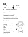
DVM1090
DIGITAL THERMOMETER
DIGITALE THERMOMETER
THERMOMETRE NUMERIQUE
DIGITALES THERMOMETER
MULTÍMETRO DIGITAL
User Manual
Gebruikershandleiding
Manuel d’utilisation
Gebrauchsanleitung
Manual
DVM1090 – DIGITAL MULTIMETER
1. Introduction & Safety Prescriptions
Thank you for buying the DVM1090. This digital multimeter has a large LCD, a data-hold function and a backlight. It
is ideal for use in open air, workshops and schools and for home and hobby applications.
2. Safety
The meter was designed according to IEC-1010 concerning the safety requirements for electronic measuring
instruments with an overvoltage category (CAT II) and pollution 2.
Respect the following safety instructions to ensure maximum personal safety and to keep the device itself in good
working order :
•
•
•
•
•
•
•
•
•
•
•
•
•
•
•
•
•
•
Protect yourself against electroshocks.
Do not use this device for any other application than those described in this manual.
Make sure the device was not damaged in transit.
Make sure the insulation of the test leads is not damaged and/or the wire itself is not exposed.
Full compliance with safety standards can only be guaranteed if the device is used with the supplied test leads. If
necessary, they should be replaced with identical leads or leads with identical electric ratings. All test leads
should be in good working order.
Never exceed the specified limit values for the various measurement ranges.
Do not touch unused terminals when the meter is connected to a circuit.
Place the range selector switch in the highest position if the value to be measured is unknown beforehand.
Do not measure voltages > 1000V above earth ground.
Exercise extreme caution when working with voltages in excess of 60VDC or 30Vrms AC. Keep your fingers
behind the probe barriers while using the device.
Do not connect the leads to a voltage source while the function switch is in one of the following modes : current,
resistance, capacitance, inductance, temperature, frequency, diode, transistor or continuity.
Disconnect all test leads from the circuit to be tested prior to selecting a different function or range.
When performing measurements on TV's or switching power circuits, the user should keep in mind that voltage
surges may occur at test points. These surges may damage the meter.
Never perform resistance, capacitance, inductance, diode and continuity measurements on live circuits.
Never perform capacitance measurements unless the capacitor in question has been fully discharged.
Have the device checked by a qualified technician in case of malfunction.
Never use the meter if the back panel is not in place and firmly fixed.
Do not use or store the device in areas exposed to direct sunlight, high temperatures or high humidity.
2.1. Symbols
Important information with reference to safety, consult the manual !
Double insulation (Protection class II)
Earth ground
DVM1090
1
GB
DC (direct current)
Low battery
Fuse
buzzer for continuity
AC (alternating current)
AC or DC (alternating current or direct current)
CAD II
Overvoltage category II, pollution degree 2 per IEC1010-1
CAT III
Overvoltage category III, pollution degree 2 per IEC1010-1
2.2 Maintenance
• Do not remove the back cover while a voltage is being applied. Only a qualified technician should handle repairs.
• Always disconnect the test leads from all current sources before opening the meter.
• Replace the battery when the
symbol is displayed.
• Replace blown fuses with an identical one or a fuse with identical voltage and current ratings : F 200mA/250V
(quick-acting, max. resistance 2Ω), F 10A/250V (“quick-acting”).
• Use a damp cloth and a mild detergent to clean the device. Never apply abrasives or solvents to the meter
• Place the power switch in the OFF position when the device is not being used
• Remove the batteries to keep them from leaking if the device is to be stored for a prolonged period of time.
3. Front Panel Description
1. LCD display
2. L/C button : press this button prior to each individual
capacitance and inductance measurement in order to
calibrate the device.
3. Power button ( )
4. Range selector : used to select the desired function and
range
5. Front panel
6. Battery cover
7. 10A jack
8. Capacitor and Ω, °C, A, V, Hz and H-jack
9. COM jack
10. DC/AC button (DC/AC) : used for AC/DC voltage and
AC/DC current measurements. Place the button in the
pressed-down position for AC current or voltage
measurements or put it in the depressed position for DC
current and voltage measurements.
11. Backlight button (LIGHT)
12. Data-hold button (HOLD)
DVM1090
2
GB
4. Specifications
Max. accuracy is achieved during a one-year period after calibration. Ideal circumstances require a temperature of 18
to 28°C (64 to 82°F) and a max. relative humidity of 75%.
4.1 General Specifications
Measuring Method
Sampling Time
Display
Max. Display
Polarity Indication
Overrange Indication
Displayed Measuring Unit
Dual-slope integration A/D converter
±0.4sec.
LCD 25mm
1999 points (3 ½ digits)
“-“ indicates negative polarity
“1”
Unit of electrical capacity
Battery-Low Indication
Maximum Altitude
Max. voltage between terminals and earth
Fuse Protection
“
”-symbol is displayed
7000ft (2000m)
1000V DC or AC
F 200mA/250V (quick-acting, max. resistance 2Ω), F 10A/250V (quickacting)
9V-battery (e.g. 6F22)
0°C to +40°C (+32 to +104°F)
-10°C to +50°C (+10 to +122°F)
185 x 84 x 38mm
±300g (battery included)
Power Supply
Operating Temperature
Storage Temperature
Dimensions
Weight
4.2 Electrical Specifications
4.2.1. DC Voltage
Range
200mV
2V
20V
200V
1000V
Resolution
0.1mV
1mV
10mV
100mV
1V
Accuracy
±0.5% of rdg + 1 digit
±0.5% of rdg + 3 digits
±0.5% of rdg + 3 digits
±0.5% of rdg + 3 digits
±0.8% of rdg + 3 digits
Input Impedance
: 10MΩ
Overload Protection : 250V DC or rms AC for the 200mV-range, 1000V DC or 700V rms AC for the ranges 2V to
1000V
Max. Input Voltage : 1000V DC
NOTE
Make sure the test leads are actually touching the circuit when performing measurements in the lower voltage
ranges. The reading will fluctuate if the leads don’t touch the circuit.
DVM1090
3
GB
4.2.2. AC Voltage
Range
200mV
2V
20V
200V
700V
Input Impedance
Overload Protection
Frequency Range
Response
Max. Input Voltage
Resolution
0.1mV
1mV
10mV
100mV
1V
Accuracy
±1.2% of rdg + 5 digits
±1.0% of rdg + 5 digits
±1.0% of rdg + 5 digits
±1.0% of rdg + 5 digits
±1.2% of rdg + 5 digits
: 10MΩ
: 250V DC or rms AC for the 200mV-range, 1000V DC or 700V rms AC for the ranges 2V to
700V
: 40 to 400Hz
: average response, calibration in rms of a sine wave.
: 700V rms AC
NOTE
Make sure the test leads are actually touching the circuit when performing measurements in the lower voltage
ranges. The reading will fluctuate if the leads don’t touch the circuit.
4.2.3. DC Current
Range
2mA
20mA
200mA
10A
Resolution
1µA
10µA
100µA
10mA
Accuracy
±1.0% of rdg + 3 digits
±1.0% of rdg + 3 digits
±1.5% of rdg + 5 digits
±2.0% of rdg + 10 digits
Overload Protection : F1 : F 200mA/250V fuse (quick-acting, max. resistance 2Ω) for the ranges 2 to 200mA, F2 : F
10A/250V fuse (quick-acting) for the 10A-range.
Max. Input Current : mA jack : 200mA, 10A jack : 10A
Voltage Drop
: 200mV
4.2.4. AC Current
Range
2mA
20mA
200mA
10A
Resolution
1µA
10µA
100µA
10mA
Accuracy
±1.2% of rdg + 5 digits
±1.2% of rdg + 5 digits
±2.0% of rdg + 5 digits
±3.0% of rdg + 10 digits
Overload Protection : F1 : F 200mA/250V fuse (quick-acting, max. resistance 2Ω) for the ranges 2 to 200mA, F2 : F
10A/250V fuse (quick-acting) for the 10A-range.
Max. Input Current : mA jack : 200mA, 10A jack : 10A
Voltage Drop
: 200mV
Frequency Range : 40 to 400HZ
Response
: average response, calibration in rms of a sine wave.
DVM1090
4
GB
4.2.5. Resistance
Range
200Ω
2kΩ
20kΩ
200kΩ
2MΩ
20MΩ
Resolution
0.1Ω
1Ω
10Ω
100Ω
1kΩ
10kΩ
Accuracy
±1.0% of rdg ± 3 digits
±1.0% of rdg ± 1 digits
±1.0% of rdg ± 1 digits
±1.0% of rdg ± 1 digits
±1.0% of rdg ± 1 digits
±1.0% of rdg ± 5 digits
Open-Circuit Voltage : ±700mV
Overload Protection : 250V DC or rms
4.2.6. Capacitance
Range
2nF
20nF
200nF
2µF
20µF
Resolution
1pF
10nF
0.1nF
1nF
10nF
Accuracy
±4.0% of rdg ± 8 digits
±4.0% of rdg ± 3 digits
±4.0% of rdg ± 3 digits
±4.0% of rdg ± 3 digits
±4.0% of rdg ± 5 digits
Overload Protection : F1 : F 200mA/250V fuse (quick-acting, max. resistance 2Ω)
4.2.7. Inductance
Range
2mH
20mH
200mH
2H
20H
Resolution
0.001mH
0.01mH
0.1mH
1mH
10mH
Accuracy
±4.0% of rdg ± 8 digits
±4.0% of rdg ± 3 digits
±4.0% of rdg ± 3 digits
±4.0% of rdg ± 3 digits
±4.0% of rdg ± 5 digits
Overload Protection : F1 : F 200mA/250V fuse (quick-acting, max. resistance 2Ω)
Tested Inductance : Q ≥ 10, internal impedance ≤ 1kΩ
4.2.8. Temperature
Range
-20 to 0°C
0 to 400°C
401 to 1000°C
Resolution
1°C
1°C
1°C
Accuracy
±5.0% of rdg + 4 digits
±1.0% of rdg ± 3 digits
±2.0% of rdg ± 3 digits
Overload Protection : F1 : F 200mA/250V fuse (quick-acting, max. resistance 2Ω)
DVM1090
5
GB
4.2.9. Frequency
Range
20KHz
Resolution
10Hz
Accuracy
±1.5% of rdg + 5 digits
Sensitivity
: 200mV rms and input no more than 10V rms
Overload Protection : 250V rms AC
4.2.10. Transistor hFE
Range
hFE
Function
Read the approximate hFE value (0-1000) of the
transistor under test (ALL TYPES) from the display
4.2.11. Diode
Range
Resolution
1mV
Function
Read the diode’s approximate forward
voltage value from the display
Forward DC Current : 1mA
Reversed DC Voltage : ±2.8V
Overload Protection : 250V DC or rms AC
4.2.12. Continuity
Range
Function
Built-in buzzer sounds if continuity exists (resistance < 50Ω)
Open Circuit Voltage : ±2.8V
Overload Protection : 250V DC or rms
4.2.13. TTL Logic
Range
DVM1090
Function
The LCD displays ▼ when the logic level ≤ 0.8V.
The LCD displays ▲ when the logic level ≥ 2.0V
6
GB
5. Operating Instructions
5.1. Using the Data Hold Button
Press this button if you want the device to hold the measured value. Press this button again to disengage the data
hold button.
5.2. Backlight
Press the LIGHT button when it’s getting too dark to read the LCD.
The backlight extinguishes automatically after 5 seconds. Using the backlight often will shorten the life of your
batteries.
The
symbol is displayed when the battery voltage is less than 7V. Note, however, that this symbol may be
displayed because you are using the backlight (which uses a lot of power), even though the actual battery charge >
7V. In other words, you should only replace the battery if the
being used.
symbol is displayed when the backlight is not
5.3. Selecting DC or AC
Press the DC/AC button to alternate between DC and AC measurements. The button is pressed in for AC voltage
and AC current measurements.
5.4. Selecting L or C
Put the button in the pressed-down position for inductance and capacitance measurements. The component can now
be tested.
Put the button in the depressed position for all other types of measurement.
5.5. Preparation for Measurement
1. Press the
button. The
symbol is displayed when the battery voltage < 7V, indicating that the battery
needs to be replaced.
next to the input jack means that the input voltage or current should not exceed the specified limit values
2. The
in order to prevent damage to the meter.
3. Select a function and a range with the range switch. Place the range selector in the highest position if the range is
unknown beforehand.
4. First connect the black test lead (mass) and then the red one (+) to avoid electroshocks.
5.6. Measuring DC Voltage
WARNING
Do not exceed the max. input voltage of 1000V DC !! Be very careful and avoid electroshocks when working with
high voltages.
1. Connect the black test lead to the COM jack and the red test lead to the V jack.
DVM1090
7
GB
2. Set the range switch at the desired V-range position.
3. Connect the test leads with the source or load under measurement.
4. Read the measured value from the LCD. The polarity of the red lead connection is also indicated.
REMARKS
• The LCD displays the overrange indication “1” if the measured value is too high for the range you are using.
Select a higher range.
• Place the range selector in the highest position if the value to be measured is unknown beforehand.
5.7. Measuring AC Voltage
WARNING
The input voltage should not exceed 700Vrms AC. Be very careful and avoid electroshocks when working with high
voltages.
1. Connect the black test lead with the COM jack and the red test lead with the V jack.
2. Set the range switch at the desired V-range position.
3. Press the DC/AC button to install the AC measuring mode.
4. Connect the test leads with the source or load under measurement.
5. Read the value from the LCD.
REMARKS
• The LCD displays the overrange indication “1” if the measured value is too high for the range you are using.
Select a higher range.
• Place the range selector in the highest position if the value to be measured is unknown beforehand.
5.8. Measuring DC Current
WARNING
Deactivate the circuit to be tested before connecting it to the meter.
1. Connect the black test lead with the COM jack and the red test lead with the A jack for current measurements up
to 200mA. Move the red lead to the 10A jack for measurements up to 10A.
2. Select the desired A-range with the range switch.
3. Connect the test leads in series with the load under measurement.
4. Read the measured value from the LCD. The measured voltage value and the polarity of the red connection are
displayed.
REMARKS
• The LCD displays the overrange indication “1” if the measured value is too high for the range you are using.
Select a higher range.
• Place the range selector in the highest position if the value to be measured is unknown beforehand.
: the max. current for socket A is 200mA, the max. current for the 10A socket is 10A.
• Respect the limit values
The fuse will blow if the limit values are exceeded.
DVM1090
8
GB
5.9. Measuring AC Current
WARNING
Deactivate the circuit to be tested before connecting it to the meter.
1. Connect the black test lead with the COM jack and the red test lead with the A jack for current measurements up
to 200mA. Move the red lead to the 10A jack for measurements up to 10A.
2. Select the desired A-range with the range switch.
3. Select the AC measuring mode with the DC/AC button.
4. Connect the test leads in series with the load to be measured.
5. Read the value from the LCD.
REMARKS
• The LCD displays the overrange indication “1” if the measured value is too high for the range you are using.
Select a higher range.
• Place the range selector in the highest position if the value to be measured is unknown beforehand.
: the max. current for socket A is 200mA, the max. current for the 10A socket is 10A.
• Respect the limit values
The fuse will blow if the limit values are exceeded.
5.10. Resistance Measurements
WARNING
Disconnect the circuit to be tested and make sure that all capacitors are fully discharged before measuring the incircuit resistance.
1. Connect the black test lead with the COM jack and the red test lead with the Ω jack.
2. Select the desired Ω range with the range switch.
3. Connect test leads with the resistance under measurement.
4. Read the value from the LCD.
REMARKS
• The LCD displays the overrange indication “1” if the measured value is too high for the range you are using.
Select a higher range.
• The meter may need a few seconds to display a stable reading when measuring resistances > 1MΩ.
• The overrange indication “1” is displayed when the input is not connected e.g. in case of an open circuit.
5.11. Capacitance Measurements
WARNING
Disconnect the test leads from the circuits to be measured before testing a capacitor in order to avoid electroshocks.
Also make sure the capacitors have been discharged fully before inserting them into the socket.
1. Connect the black test lead with the COM jack and the red test lead with the jack.
2. Select the desired F range with the range switch and press the L/C button.
3. Make sure the capacitor has been fully discharged and connect the test leads with the capacitor to be tested.
DVM1090
9
GB
4. Read the value from the LCD.
5. When frequent capacitance testing is needed you should connect the multifunction socket (included) with the
COM & V/Ω/A sockets. Insert the capacitor’s pins in the “+” and “-“ connectors of the multifunction socket.
REMARKS
• When measuring low capacities, the reading will include the capacity of the measuring leads. However, this will
not influence the accuracy of your measurements.
• The device will need some time to produce a stable reading when measuring high capacitance values.
5.12. Inductance Measurements
1.
2.
3.
4.
5.
Connect the black test lead with the COM jack and the red test lead with the H jack.
Place the range switch in the desired H range position and press the L/C button.
Connect the test leads with two points of the inductor to be tested.
Read the value from the LCD.
When frequent inductance testing is needed you should connect the multifunction socket (included) with the COM
& V/Ω/A sockets. Insert the inductor’s pins in the “+” and “-“connectors of the multifunction socket.
REMARKS
Keep in mind that precise inductance measurements are impossible in close vicinity to strong magnetic fields.
5.13. Temperature Measurements
WARNING
Do not connect the thermocouples with electrical circuits in order to avoid electroshocks.
1. Put the range switch in the °C-range position.
2. The LCD displays the current environmental temperature.
3. Insert “K”-type thermocouples into the COM jack and V/Ω/A jack (or you can use the multifunction socket to
connect a different type of K-thermocouple).
4. Read the value from the LCD.
5.14. Frequency Measurements
1.
2.
3.
4.
Connect the black test lead with the COM jack and the red test lead with the Hz jack.
Place the range switch in the 20KHz range position.
Connect the test leads with the source or load to be tested.
Read the value from the LCD.
REMARKS
• It is possible to obtain a reading with input voltages above 10Vrms, but the accuracy is not guaranteed.
• Use shielded cable to measure small signals in a noisy environment.
DVM1090
10
GB
5.15. Diode Test
1.
2.
3.
4.
Connect the black test lead with the COM jack and the red test lead with the V jack.
Place the range switch in the
range position.
Connect the red lead with the anode and the black lead with the cathode of the diode to be tested.
Read the value from the LCD.
REMARKS
• The LCD will display the possible forward voltage drop of the diode.
• The overrange indication “1” will be displayed if the leads have not been connected properly.
• The overrange indication “1” is displayed when the input is not connected e.g. in case of an open circuit.
5.16. Continuity Test
Disconnect the test leads from the circuits to be measured before testing a capacitor in order to avoid electroshocks.
Also make sure the capacitors have been discharged fully before inserting them into the test socket.
Deactivate the circuit to be tested and make sure all capacitors have been fully discharged prior to measuring the
circuit’s continuity.
1. Connect the black test lead with the COM jack and the red test lead with the Ω jack.
2. Place the range switch in the desired
range position.
3. Connect the test leads with two points of the circuit to be tested.
4. The built-in buzzer will sound if continuity exists.
REMARKS
• The overrange indication “1” is displayed when the input is not connected e.g. in case of an open circuit.
5.17. Transistor Test
1. Put the rotary switch in the hFE-position.
2. Plug the multifunction socket into the COM jack and the V jack.
3. Identify whether the transistor is NPN or PNP type and locate the emitter, the base and the collector. Insert the
leads into the proper holes of the transistor on the multifunction socket for testing.
4. Read the value from the LCD.
5.18. TTL Logic Test
1. Connect the black test lead with the COM jack and the red test lead with the V jack.
2. Put the range switch in the range position.
3. Connect the test leads with two points of the circuit to be tested.
4. When the logic level is ≤ 0.8V, the LCD will display ▼ and the buzzer will sound. The LCD displays ▲ when the
logic level ≥ 2.0V.
DVM1090
11
GB
6. Maintenance
6.1. Replacing the battery
In order to avoid electroshocks, you should disconnect the test leads before opening the case or the battery
compartment.
1. The
sign appears on the LCD display when the battery needs to be replaced.
2. Loosen the fixing screw of the case and remove the battery cover on the front panel.
3. Insert the new 9V-battery and replace the battery cover.
6.2. Replacing the Fuse
Disconnect all test leads before replacing the fuse in order to avoid electroshocks. In order to avoid unnecessary fire
risks, you should only use fuses with the following ratings : F1 : F 200mA/250mV (quick-acting, resistance ≤ 2Ω), F2
: F 10a/250V (quick-acting).
6.3. Replacing Test Leads
Only when you use the supplied test leads can we guarantee that you are complying fully with the safety standards. If
necessary, they should be replaced with test leads of the same model or with the same ratings. Electric ratings of the
test leads : 1000V 10A.
7. Accessories
•
•
•
•
•
•
test leads : max. 1000V
9V-battery (e.g. 6F22)
user manual
holster
thermocouple (“K”-type)
multifunction test socket
DVM1090
12
GB