1
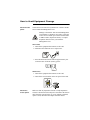
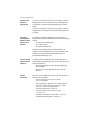
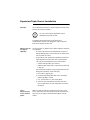
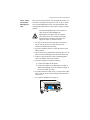
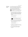
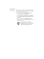
Network
Management
Card
AP9617
AP9618
AP9619
Installation and
Quick-Start Manual
®
How to Avoid Equipment Damage
Disconnect UPS
power
You do not need to turn off a Symmetra® or a Silcon™ model
UPS to install the Management Card.
Caution
Damage to the UPS or APC Network Management
Card (AP9617 or AP9618) can result if you do not
remove all AC and DC power from a Smart-UPS®
or Matrix-UPS®, Expansion Chassis, or a Triple
Expansion Chassis before you install the
Management Card.
Smart-UPS
1. Turn off the equipment that connects to the UPS.
2. Disconnect the UPS from its AC input source.
3. Press the OFF button on the UPS for approximately five
seconds to turn off the DC (battery) power.
Matrix-UPS
1. Turn off the equipment that connects to the UPS.
2. Turn off the circuit breaker on the rear panel of the UPS.
Disconnect
chassis power
Make sure that any Expansion Chassis or Triple Expansion
Chassis is disconnected from all power: disconnect the chassis
cable from the UPS and, if the AC-to-DC Adapter (AP9505)
option is used, disconnect the adapter from the chassis.
How to Recover from a Lost Password
You can use a local computer, a computer that connects to the
Management Card through the serial port at the Management
Card’s UPS or expansion chassis, to access the Control
Console.
1. Select a serial port at the local computer and disable any
service that uses that port.
2. Unless an APC smart-signaling cable (940-0024 or 9401524) is already connected to the selected port, connect
the smart-signaling cable that came with the Management
Card to the selected port and to the serial port at the
Management Card’s UPS or chassis.
3. Run a terminal program (such as HyperTerminal) and
configure the selected port for 2400 bps, 8 data bits, no
parity, 1 stop bit, and no flow control, and save the
changes.
4. Press ENTER to display the User Name prompt.
5. Press the reset button on the Management Card.
6. Press ENTER and use apc for the User Name and
Password. (If you take longer than 30 seconds to log on,
you will need to repeat steps 4 and 5.)
7. Select System in the Control Console menu and User
Manager in the System menu.
8. Select Administrator and follow the on-screen
instructions to change the User Name and Password
settings, both of which are now defined as apc.
9. Press CTRL-C and log off.
Reconnect any cable disconnected in step 2,
and restart any service disabled in step 1.
Note
Preliminary Information
New standard
features
The AP9617, AP9618, and AP9619 Management Cards
include the following new features:
• Generates system log (Syslog) messages
• Allows using a dynamic host configuration protocol
(DHCP) server to provide the TCP/IP values a Network
Management Card needs for network communication
Existing features
All Network Management Cards still include the following
standard features:
• Detects 10/100 Mbps connection speeds
• Provides a data log accessible by FTP or a Web browser
• Provides UPS scheduling features
• Provides support for the APC PowerChute Network
Shutdown utility
• Provides an event log which is accessible by Telnet, FTP,
or a Web browser
• Generates Email notifications for UPS or system events
• Limits SNMP traps and Email notifications based on the
severity level of the events
• Allows using the APC Management Card Wizard to
configure multiple Management Cards simultaneously
over the network
• Provides support for APC Silcon UPS models
• Provides UPS-specific application modules based on the
Management Card’s hardware platform, and the
application module’s
AP9618 features
The AP9618 Network Management Card EM/MDM includes
the analog modem and Integrated Environmental Monitor
features described on page 4.
AP9619 features
The AP9619 Network Management Card EM includes the
Integrated Environmental Monitor features described on page
4; the AP9619 does not include the analog modem feature.
Preliminary Information
AP9618U and
AP9619U
upgrade kits
You can use an AP9618U kit to convert an AP9617 Network
Management Card EX or an AP9619 Network Management
Card EM into an AP9618 Network Management Card EM/
MDM.
You can use an AP9619U kit to convert an AP9617 Network
Management Card EX into an AP9619 Network Management
Card EM.
Integrated
Environmental
Monitor feature
(AP9618 and
AP9619)
The AP9618 and AP9619 Management Cards include an
Integrated Environmental Monitor that provides the following
features:
• A temperature/humidly probe
• Two input contacts
• Two-position output relay
In addition to the Integrated Environmental Monitor, an
AP9618 or AP9619 Management Card can still monitor and
manage an external Environmental Monitoring Unit or
Environmental Monitoring Card.
Internal analog
modem feature
(AP9618)
An AP9618 Network Management Card EM/MDM has an
internal analog modem that provides for the following out-ofband communication:
• Dial-out notifications for APC’s Remote Monitoring
Service (RMS)
• Dial-in access to the Management Card’s Console
Interface
Related
documents
The APC Network Management Card utility CD contains the
following documentation:
• Network Management Card User’s Guide
(.\doc\usrguide.pdf)
• Management Card Addendum (.\doc\addendum.pdf)
• PowerNet® Management Information Base (MIB)
Reference Guide (.\doc\mibguide.pdf)
• CD-ROM contents file (.\content.txt)
• Network Management Card Release Notes
(.\relnotes.txt)
• Installation instructions in text format (.\install.txt)
• Troubleshooting documents (.\trouble\*.*)
Installation in a UPS
Overview
You can install the Management Card in a card slot in a
Smart-UPS, Matrix-UPS, or Symmetra. For a Silcon UPS, the
Management Card installs in a Silcon Triple Expansion
Chassis (AP9604S).
Step 1: Turn off
all power
(Smart-UPS or
Matrix-UPS)
You do not need to turn power off for a Symmetra UPS.
Caution
Damage to the UPS or Management Card can
result if you do not remove all AC and DC power
from a Smart-UPS or Matrix-UPS model UPS.
Smart-UPS
1. Turn off the equipment that connects to the UPS.
2. Disconnect the UPS from its AC input source.
3. Press the OFF button on the UPS for approximately five
seconds to turn off the DC (battery) power.
Matrix-UPS
1. Turn off the equipment that connects to the UPS.
2. Turn off the circuit breaker on the rear panel of the UPS.
Installation in a UPS
Step 2: Install
the Network
Management
Card
If you are installing the Management Card in a Symmetra UPS
that uses more than one APC management product, see
Installation of Multiple Management Cards, a copy of which
came with the Management Card. You must install the APC
management products in the correct order for them to operate
properly.
Caution
The Network Management Card is sensitive to
static electricity. When handling the
Management Card, touch only the end plate
while using one or more of these electrostaticdischarge devices (ESDs): wrist straps, heel
straps, toe straps, or conductive shoes.
1. Use the same screws that hold the slot cover in place to
secure the Management Card in the UPS card slot.
2. Connect a network interface cable to the 10/100Base-T
network connector on the Management Card.
3. Reconnect the UPS to its input power source.
4. Turn on the UPS.
5. See “Quick Configuration” on page 10.
Probe
Modem
Expansion/Triple Chassis Installation
Overview
Use an Expansion Chassis or a Triple Expansion Chassis if the
UPS has no card slot available.
Use only a Silcon Triple Expansion Chassis
(AP9604S) with a Silcon UPS.
Note
The Management Card installs in the chassis and
communicates with the UPS through the cable connection
between the chassis and the UPS.
When to use the
AC adapter
(AP9505)
Use the optional AC adapter with a chassis under the following
circumstances:
• To connect the chassis to an independent AC input so
that the Management Card can continue to operate if the
UPS is turned off or fails.
• To provide the APC management products mounted in a
Triple Expansion Chassis with more current than the
UPS can provide through the UPS-to-chassis cable.
– A Silcon UPS provides up to 500 mA.
– A Matrix-UPS, Smart-UPS, or Symmetra provides up
to 200 mA.
For information about the current requirements for APC
management products, do the following:
a. Go to APC’s Support page
b. Click the Knowledge Base link in the “Search the
Knowledge Base” section.
c. Use “current draw” as your search phrase.
d. Select the “Recommended connection order and
power requirements for APC SmartSlot accessories”
document.
Step 1:
Disconnect the
chassis from all
power
Make sure that the chassis is disconnected from any power
source: Disconnect the chassis cable from the UPS and, if the
UPS uses an AC adapter, disconnect that adapter from the
chassis.
Expansion/Triple Chassis Installation
Step 2: Install
the Network
Management
Card
If the UPS uses more than one APC management product, see
Installation of Multiple Management Cards, a copy of which
came with the Management Card. You must install the APC
management products in the correct order for them to operate
properly.
Caution
The Network Management Card is sensitive to
static electricity. When handling the
Management Card, touch only the end plate
while using one or more of these electrostaticdischarge devices (ESDs): wrist straps, heel
straps, toe straps, or conductive shoes.
1. If a cable is connected to the serial port at the UPS or
chassis, stop the APC service that uses that serial
connection and disconnect the cable.
2. If you are installing a chassis, connect the chassis to the
UPS serial port.
3. Use the same screws that hold the expansion slot cover in
place to secure the Management Card in the chassis slot.
4. Connect a network interface cable to the Management
Card’s 10/100Base-T network connector.
5. If you are using the AC Adapter (AP9505):
a. Connect the adapter to the chassis.
b. Connect the adapter to an independent AC input so
that the Management Card can continue to operate if
the UPS is turned off or fails.
6. If you disconnected a cable in step 1, reconnect that cable
to the serial port at the chassis, and restart the associated
APC service.
7. See “Quick Configuration” on page 10.
Probe
Modem
8
Quick Configuration
Overview
You must configure the following TCP/IP settings before the
Management Card can operate on a network:
• The IP address of the Management Card
• The subnet mask
• The default gateway
If a default gateway is unavailable, use the
IP address of a computer located on the
Note
TCP/IP
configuration
methods
same subnet as the Management Card that
is usually running. The Management Card
uses the default gateway to test the network
when traffic is very light. See “Watchdog
Features” in the “Introduction” of the
Network Management Card User’s Guide
(.\doc\usrguide.pdf) for more information
about the watchdog role of the default
gateway.
Use one of the following methods to define the TCP/IP settings
needed by the Management Card:
• The APC Management Card Wizard (see “APC
Management Card Wizard” on page 11)
• A DHCP or BOOTP server (see “BOOTP & DHCP
configuration” on page 11)
• A local computer (see “Local access to the control
console” on page 14)
• A networked computer (see “Remote access to the
control console” on page 15)
Quick Configuration
APC
Management
Card Wizard
You can use the APC Management Card Wizard at a Windows
95, Windows 98, Windows NT 4.0, or Windows 2000
computer to configure a Management Card.
To configure multiple Management Cards, or to
configure a Management Card from a
configuration file, see the Management Card
Addendum (.\doc\addendum.pdf).
1. Follow the on-screen instructions to install the Wizard
from the APC Network Management Card utility CD.
2. Launch the Wizard, when prompted, or, if prompted to
restart the computer, access the Wizard from the Start
menu after the computer has restarted.
3. Wait for the Wizard to discover the unconfigured
Management Card, then follow the on-screen instructions.
Note
BOOTP & DHCP
configuration
If you leave the Start a Web browser when
finished option enabled, you can use apc for
both the User Name and Password to access
the Management Card through your browser.
The Boot Mode setting, a TCP/IP option in the Management
Card’s Network menu, identifies how the TCP/IP settings will
be defined. The possible settings are Manual, DHCP only,
BOOTP only, and DHCP&BOOTP (the default setting).
Note
The DHCP&BOOTP setting assumes that a
properly configured DHCP or BOOTP server is
available to provide TCP/IP settings to APC
Network Management Cards. If these servers are
unavailable, see “APC Management Card
Wizard” on page 11, “Local access to the control
console” on page 14, or “Remote access to the
control console” on page 15 to configure the
needed TCP/IP settings.
With Boot Mode set to DHCP&BOOTP, the Management
Card attempts to discover a properly configured server. It first
searches for a BOOTP server, then a DHCP server, and repeats
this pattern until it discovers a BOOTP or DHCP server.
For more information about using a server to
configure a Management Card’s TCP/IP settings,
see “BOOTP” on page 12 or “DHCP” on page 13.
Quick Configuration
BOOTP. You can use an RFC951-compliant BOOTP server to
configure the TCP/IP settings the Management Card needs.
1. Enter the Management Card’s MAC and IP addresses, the
subnet mask, and default gateway settings, and an optional
Bootup File Name in the BOOTPTAB file of the BOOTP
server.
See the Network Management Card Quality
Assurance slip for the MAC address.
2. When the Management Card reboots, the BOOTP server
provides it with the TCP/IP settings.
– If you specified a bootup file name, the Management
Card will attempt to transfer that file from a TFTP or
FTP server residing on the BOOTP server. The
Management Card will assume all settings specified in
the bootup file.
– If you did not specify a bootup file name, the
Management Card can be configured remotely by using
Telnet or by using the Web interface: User Name and
Password are both apc, by default.
You must use the APC Management
Card Wizard or the APC initialization
(*.ini) text-to-binary configuration
(*.cfg) conversion utility, i2c300, to
create the bootup file. To create a bootup
file, see the BOOTP section in the
Management Card Addendum
(.\doc\addendum.pdf).
Quick Configuration
DHCP. You can use a RFC2131/RFC2132-compliant DHCP
server to configure the TCP/IP settings the Management Card
needs.
This section briefly summarizes the Management
Card communication with a DHCP server. For
more detail about how a DHCP server is used to
configure the network settings for a Management
Card, see “DHCP Configuration” in the Network
Management Card User’s Guide
(.\doc\usrguide.pdf).
1. A Management Card sends out a DHCP request that use
the following to identify itself:
– A Vendor Class Identifier (APC by default)
– A Client Identifier (by default, the Management Card’s
MAC address value)
– A User Class Identifier (by default, the identification of
the Management Card’s application firmware)
2. A properly configured DHCP server responds with a
DHCP offer that includes all of the settings that the
Management Card needs for network communication. The
DHCP offer also includes the Vendor Specific Information
option (DHCP option 43). By default, the Management
Card will ignore DHCP offers that do encapsulate the APC
cookie in the Vendor Specific Information option using
the following hexidecimal format:
Option 43 = 01 04 31 41 50 43
where
– the first byte (01) is the code
– the second byte (04) is the length
– the remaining bytes (31 41 50 43) are the APC
cookie
Refer to your DHCP server documentation
for information about adding code to the
Vendor Specific Information option. To
disable the APC cookie requirement, see
“Local access to the control console” on
page 14 or “Remote access to the control
console” on page 15 to change the control
console’s DHCP Cookie Is setting, an
Advanced option in the TCP/IP menu.
Quick Configuration
Local access to
the control
console
You can use a local computer, a computer that connects to the
Management Card through the serial port at the Management
Card’s UPS or expansion chassis, to access the Control
Console.
1. Select a serial port at the local computer and disable any
service that uses that port.
2. Unless an APC smart-signaling cable (940-0024 or 9401524) is already connected to the selected port, connect
the smart-signaling cable that came with the Management
Card to the selected port and to the serial port at the
Management Card’s UPS or chassis.
3. Run a terminal program (such as HyperTerminal) and
configure the selected port for 2400 bps, 8 data bits, no
parity, 1 stop bit, and no flow control, and save the
changes.
4. Press ENTER to display the User Name prompt.
5. Use apc for the User Name and Password.
6. See “Control console” on page 16 to finish the
configuration.
Quick Configuration
Remote access
to the control
console
From any computer on the same subnet as the Management
Card, you can use ARP and Ping in a process known as
gleaning, to assign an IP address to a Management Card, and
then use Telnet to access that Management Card’s control
console and configure the needed TCP/IP settings.
Note
After a Management Card has its IP address
configured, you can use Telnet, without first using
ARP and Ping, to access that Management Card.
1. Use ARP to define an IP address for the Management
Card, and use the Management Card’s MAC address in the
ARP command. For example, to define an IP address of
159.215.15.141 for a Management Card that has a MAC
address of 00 c0 b7 63 9f 67, use one of the following
commands:
– Windows command format:
arp -s 159.215.15.141 00-c0-b7-63-9f-67
– LINUX command format:
arp -s 159.215.15.141 00:c0:b7:63:9f:67
The Network Management Card quality
assurance test slip lists the MAC address.
2. Use Ping with a size of 113 bytes to assign the IP address
defined by the ARP command. For the IP address defined
in step 1, use one of the following Ping commands:
– Windows command format:
ping 159.215.15.141 -l 113
– LINUX command format:
ping 159.215.15.141 -s 113
3. Use Telnet to access the Management Card at its newly
assigned IP address. For this example, use this command:
telnet 159.215.15.141
4. Use apc for both the User Name and Password.
5. See “Control console” on page 16 to finish the
configuration.
Quick Configuration
Control console
After you log on at the control console, as described in either
“Local access to the control console” on page 14 or “Remote
access to the control console” on page 15:
1. Choose Network from the Control Console menu.
2. Choose TCP/IP from the Network menu.
3. If necessary, change the Boot Mode setting to Manual.
4. Set the System IP, Subnet Mask and Default Gateway
address values.
5. Press CTRL-C to exit to the Control Console menu.
6. Log out (option 4 in the Control Console menu) to have
the changes take effect.
Note
If you disconnected a cable during the
procedure described in “Local access to the
control console” on page 14, reconnect that
cable and restart the associated service.
How to Access a Configured Network
Management Card
Overview
Once the Management Card is running on your network, you
can use several different interfaces to access the Management
Card.
Note
Web interface
For more information about how to use the
interfaces identified here, see the Network
Management Card User’s Guide
(.\doc\usrguide.pdf) and the Management Card
Addendum (.\doc\addendum.pdf).
You can use Internet Explorer 5.0 (and higher) or Netscape®
4.0.8 (and higher) browsers to configure Management Card
options, or to view the Event log.
1. Address the Management Card by its IP address or DNS
name (if configured).
2. Enter the User Name and Password (apc by default).
Telnet
You can use Telnet to access a Management Card’s Control
Console from any computer on the same subnet.
1. At a command prompt, type telnet <address> and
press ENTER at a command prompt, where
<address> is the Management Card’s IP address or
DNS name (if configured).
2. Enter the User Name and Password (apc by default).
SNMP
After you add the PowerNet MIB to a standard SNMP MIB
browser, you can use that browser for SNMP access to a
Management Card. The default read community name is
public; the default read/write community name is private.
How to Access a Configured Network Management Card
FTP
You can use FTP (enabled by default) to download new
firmware to a Management Card, or to access a copy of a
Management Card’s event or data logs.
1. At a command prompt, type ftp address and press
ENTER, where address is the Management Card’s IP
address.
2. Enter the User Name and Password (apc by default).
APC
Management
Card Wizard
You can use the APC Management Card Wizard to configure
multiple Management Cards over the network.
Analog modem
(AP9618)
The AP9618 Network Management Card EM/MDM has an
internal analog modem you can use for dial-in access to its
Management Card’s control console.
Radio Frequency Interference
Warning
Changes or modifications to this unit not
expressly approved by the party responsible
for compliance could void the user’s authority
to operate this equipment.
This equipment has been tested and found to comply with the
limits for a Class A digital device, pursuant to part 15 of the
FCC Rules. These limits are designed to provide reasonable
protection against harmful interference when the equipment is
operated in a commercial environment. This equipment
generates, uses, and can radiate radio frequency energy and, if
not installed and used in accordance with this user manual,
may cause harmful interference to radio communications.
Operation of this equipment in a residential area is likely to
cause harmful interference. The user will bear sole
responsibility for correcting such interference.
This Class A digital apparatus complies with Canadian
ICES-003.
Cet appareil numérique de la classe A est conforme à la norme
NMB-003 du Canada.
a
http://www.APCturkey.com