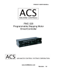
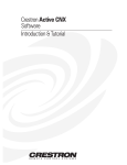
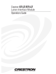
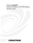
1
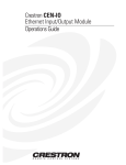
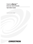
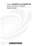
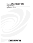
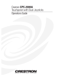
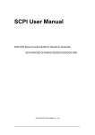
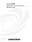
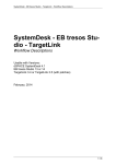
Crestron CEN-COM Ethernet RS-232/422 COM Module Contents Ethernet RS-232/422 COM Module: CEN-COM 1 Description................................................................................................................................. 1 Functional Description ................................................................................................ 1 Physical Description.................................................................................................... 2 Leading Specifications............................................................................................................... 6 Setup .......................................................................................................................................... 6 Hardware Hookup ....................................................................................................... 6 Setup Menus ................................................................................................................ 7 Stand-Alone Operations: Crestron e-control™ ......................................................... 12 SIMPL™ Windows Programming ....................................................................................... 13 How the Program Works ........................................................................................... 13 How to Create the Program ....................................................................................... 15 Problem Solving ...................................................................................................................... 18 Troubleshooting......................................................................................................... 18 Further Inquiries ........................................................................................................ 18 Return and Warranty Policies .................................................................................................. 19 Merchandise Returns / Repair Service ...................................................................... 19 CRESTRON Limited Warranty................................................................................. 19 Glossary of Terms Operations Guide - DOC. 5719 20 Contents • i Crestron CEN-COM Ethernet RS-232/422 COM Module Ethernet RS-232/422 COM Module: CEN-COM Description Functional Description The CEN-COM is an Ethernet device with two independent bidirectional serial ports that can support either asynchronous RS-232 or RS-422-based communication. The unit enables a system to overcome the distance limitations of RS-232/RS-422 communication. All signals are monitored/controlled via 10BASE-T Ethernet using standard Internet protocols. Both ports of the CEN-COM may be used to control a wide variety of RS-232 or asynchronous RS-422 controlled equipment. A variety of communications parameters are supported. Valid parameters are as follows. Operations Guide - DOC. 5719 • Baud rates may be one of the following possible rates: 300, 1200, 1800, 2400, 3600, 4800, 6100, 7200, 9600, 14400, 19200, 28800, 38400, 57600, and 115200. • Parity may be even, odd, none, or zero stick (parity bit always 0). When specifying the parity use E, O, N, or Z, respectively. • Data bits may be 7 or 8. • Stop bits may be 1 or 2. • Both XON/XOFF handshaking and RTS/CTS handshaking are supported. XON/XOFF handshaking may be supported by specifying XON (for both transmit and receive), XONR (for receive only), or XONT (for transmit only). XON/XOFF and RTS/CTS handshaking are mutually exclusive in the CEN-COM. If both are enabled, RTS/CTS is used. If CTS handshaking is enabled, the CTS line is monitored by the CEN-COM. The CTS line can also be enabled as a digital input to the control system; the RTS line can be enabled as a digital output. • Specify RS422 for standard if RS-422 compatible levels must be supported. • Break of any length can be generated. Ethernet RS-232/422 COM Module: CEN-COM • 1 Ethernet RS-232/422 COM Module Crestron CEN-COM • Provides character pacing in units of milliseconds for all of the data specified. The range of the pacing is from 1 to 31 milliseconds. Pacing greater than 31 milliseconds defaults to the maximum (31 ms). • Supports RS-485. However, a specific protocol for defining the mechanism as to when a device is permitted to transmit on the RS-485 bus must be followed. To use this feature, use RS-422 communications settings. Set hardware handshaking to none. The RTS output can now be used to enable the transmitter. Notice that the receiver is always active. Therefore, transmissions are also received. Physical Description The CEN-COM is housed in a black enclosure with silk-screened labels on the front and rear panels. On the front of the unit there are 13 LEDs for indicating the unit’s current status. All connections, except for the Ethernet connection, are made on the back of the unit. Refer to the physical views shown below. There are four rubber feet on the base of the unit for stability and to prevent slippage. CEN-COM Physical Views 2 • Ethernet RS-232/422 COM Module: CEN-COM Operations Guide - DOC. 5719 Crestron CEN-COM Ethernet RS-232/422 COM Module CEN-COM Ports A number of ports are provided on the back of the CEN-COM. Each has a silkscreened label. Refer to illustration and descriptions below. The Ethernet port is located on the front panel. CEN-COM Ports 12 VDC .5 A This DC power socket connector is used to supply power via an external AC power pack. Crestron recommends specific power packs for its devices. The recommended power pack for the CEN-COM is Crestron part number PW-1205 (PWI-1210 for international use of the CENI-COM). If an external power pack other than this Crestron model is obtained, verify that it meets the required specifications and polarity as shown after this paragraph. AC Power Pack Specifications CRESTRON POWER PACK INPUT SPECS OUTPUT SPECS PW-1205 PWI-1210 120V~60Hz 230V~50Hz 12VDC .5 A 12VDC 1A AC Power Pack Polarity PC This 6-pin, 6-position RJ11 modular jack is used to load the IP address and run diagnostics. Use Crestron’s RJ11 Cable Assembly (Part Number CA15717-2, not supplied) to make the connection to the PC. Refer to the pinout table after this paragraph. PC Port (RJ11) Pinouts Operations Guide - DOC. 5719 PIN DESCRIPTION 1 2 3 4 5 6 CTS GND RXD TXD RTS No Connect Ethernet RS-232/422 COM Module: CEN-COM • 3 Ethernet RS-232/422 COM Module Crestron CEN-COM COM A / B These two 9-pin connectors (DB9) connect to serial equipment. These bidirectional serial ports are used for RS-232, RS-422, or RS-485 communication. NOTE: The pinout of each 9-pin port is non-standard (refer to table after this note); it contains RS-422 pins in addition to RS-232. This may result in a conflict with some equipment and therefore do not use all nine pins. Only the required pins for each communication type should be connected. NOTE: To support RS-485, tie pin 1 (RXD-) to pin 9 (TXD-) and pin 4 (TXD+) to pin 6 (RXD+) in the cable, as shown below. CEN-COM Pinout (COM A / B) PIN DIRECTION 1* 2 3 4 5 6 7 8 9 To CEN-COM To CEN-COM From CEN-COM From CEN-COM To CEN-COM From CEN-COM To CEN-COM From CEN-COM DESCRIPTION (RXD-) RS-422 Receive Data (Idles low) (RXD) RS-232 Receive Data (TXD) RS-232 Transmit Data (TXD+) RS-422 Transmit Data (Idles high) RS-232 and RS-422 Signal Common (RXD+) RS-422 Receive Data (Idles high) (RTS) RS-232 Request to Send (CTS) RS-232 Clear to Send (TXD-) RS-422 Transmit Data (Idles low) * RS-422/RS-485 are balanced signals requiring two lines plus a ground in each direction. RXD+ and TXD+ should idle high (going low at start of data transmission). RXD- and TXD- should idle low(going high at start of data transmission). If necessary, RXD+/RXD- and TXD+/TXD- may be swapped to maintain correct signal levels. Ethernet (on front panel) This unmarked RJ45 modular connector provides Ethernet connection, thereby making the unit IP addressable and compatible with 10BASE-T Ethernet systems. The Ethernet port is the standard 10BASE-T pinout. Refer to the pinout table after this paragraph. 4 • Ethernet RS-232/422 COM Module: CEN-COM Operations Guide - DOC. 5719 Crestron CEN-COM Ethernet RS-232/422 COM Module Ethernet Port (RJ45) Pinouts PIN DESCRIPTION 1 2 3 4 5 6 7 8 TD+ TDRD+ No Connect No Connect RDNo Connect No Connect CEN-COM Indicators There are 13 LED indicators located on the front panel of the CEN-COM. Refer to illustration and descriptions below. CEN-COM Indicators PWR (Power) This LED illuminates when power is supplied to the CEN-COM. RXD (Ethernet) This LED illuminates when the unmarked Ethernet port on the front panel of the CEN-COM receives Ethernet data. TXD (Ethernet) This LED illuminates when the unmarked Ethernet port on the front panel of the CEN-COM transmits Ethernet data. LNK (Ethernet) This LED illuminates when there are attachments to the unmarked Ethernet port on the front panel. ERR (Ethernet) This LED illuminates when an Ethernet protocol error is detected. RXD (COM A / B) These LEDs flash when the CEN-COM receives data from the serial device attached to the respective COM ports. TXD (COM A / B) These LEDs flash when the CEN-COM transmits data to the serial device attached to the respective COM ports. Operations Guide - DOC. 5719 Ethernet RS-232/422 COM Module: CEN-COM • 5 Ethernet RS-232/422 COM Module Crestron CEN-COM RTS (COM A / B) If RTS/CTS handshaking is enabled, these LEDs illuminate when the CEN-COM is ready to receive data from a serial device attached to the respective COM ports. CTS (COM A / B) These LEDs illuminate when the serial device on the respective COM port is ready to accept data from the CEN-COM. This “Clear to Send” signal is available only if RTS/CTS handshaking is enabled; signal is controlled by external serial device. If CTS signal is not connected (in cable), the signal is held high and the LEDs are extinguished. Leading Specifications The table below provides a summary of leading specifications for the CEN-COM module. Dimensions and weight are rounded to the nearest thousandth unit. Leading Specifications of the CEN-COM SPECIFICATION DETAILS Power Requirements 12 or 24 VDC, Load Factor of 2.5 Watts SIMPL™ Windows® Version 1.30.01 or later1 with the addition of smwlib45.exe and smwlib45.txt CNX Upgrade File Version 5.04.11 or later2 Crestron Database Version 11.7.210 or later1 CEN-COM Upgrade File Version 1.23 or later1 Height: 1.70 in (4.32 cm) Dimensions & Weight Width: 6.94 in (17.63 cm) Depth: 6.32 in (16.06 cm) Weight: 1.90 lb (0.86 kg) 1 The latest software versions can be obtained from the Software Downloads page (SIMPLWIN, CRESDB, and UPGRADES Libraries) of Crestron’s website (www.crestron.com). New users are required to register in order to obtain access to the FTP site. 2 Filenames for CNX upgrades have a .upz extension and can be obtained from the Software Downloads page (OPSYS Library) of the Crestron website. As of the date of manufacture, the unit has been tested and found to comply with specifications for CE marking. NOTE: This device complies with part 15 of the FCC rules. Operation is subject to the following two conditions: (1) these devices may not cause harmful interference, and (2) these devices must accept any interference received, including interference that may cause undesired operation. Setup Hardware Hookup Refer to the hookup diagram after this paragraph. Other than making the power connection last, complete the connections in any order. The only connection not 6 • Ethernet RS-232/422 COM Module: CEN-COM Operations Guide - DOC. 5719 Crestron CEN-COM Ethernet RS-232/422 COM Module shown in the diagram is the Ethernet/LAN connection made to the front panel of the unit. Use a CAT 5 cable; not supplied. Hookup Connections for CEN-COM PC (USED ONLY WHEN ACCESSING SETUP MENUS) SERIAL DEVICE POWER PACK (500 mA) (1000 mA for CENI-COM) SERIAL DEVICE NOTE: CABLES ARE NOT SUPPLIED. ETHERNET CONNECTION NOT SHOWN. Setup Menus The CEN-COM setup menus can be accessed only after connecting the communications port of the PC to the PC port on the CEN-COM. Communication cables are not provided. Refer to “Hardware Hookup” in the previous section for CEN-COM hookup details. After connecting the CEN-COM and before applying power to it, open the communications package that resides on the PC. Viewport from either SIMPL Windows or VisionTools Pro is used in the illustrations that follow. Be sure to set the PC communication parameters as shown after this paragraph. No handshaking is required. PC Communication Parameters Operations Guide - DOC. 5719 Ethernet RS-232/422 COM Module: CEN-COM • 7 Ethernet RS-232/422 COM Module Crestron CEN-COM Apply power to the CEN-COM and notice that the Viewport window changes as communication is established with the CEN-COM, shown below. Activity in the Viewport Window Enter a question mark (?) and depress ENTER to display the setup menu, shown below. Main Menu in Viewport Window At the time of printing this Operations Guide, not all commands (listed in the leftmost column) in the main menu were fully implemented. The following subsections provide a brief description of each. Command entry is not case sensitive. The user only needs to enter the characters of a command that make it unique from another (i.e., for the add_master command, the user only needs to enter “add_m”). add_master Entering the “add_master” command provides a list of IP addresses (masters) from which the CEN-COM will accept commands. Refer to the sample Master List shown after this paragraph. There are five static IP addresses which are stored in nonvolatile ROM. Also, there are three dynamic IP addresses which are not permanently stored and can therefore be lost after a power cycle. 8 • Ethernet RS-232/422 COM Module: CEN-COM Operations Guide - DOC. 5719 Crestron CEN-COM Ethernet RS-232/422 COM Module Sample Response to the “add_master” Command Each row of the master list contains an index number enclosed in brackets, the IP ID of the device to which the system communicates (provided in decimal and hex), and an IP address separated by a colon (:). Each line appears as follows. [INDEX #]decimal IP ID(hex IP ID):IP ADDRESS To add an IP address to the master list, enter the index number, the IP ID (in decimal), and the desired IP address separated by decimal points (.), after the “add_master” command. For example to add IP address 132.149.2.122 as the first static master on IP ID 03, enter the following. add_master 00.3.132.149.2.122 To delete an IP address from the master list, enter the index number, a zero, and IP address of 0.0.0.0 separated by decimal points (.), after the “add_master” command. For example, to delete the IP address that was just added, enter the following. add_master 00.0.0.0.0.0 ip_adr Enter the “ip_adr” command and depress ENTER to display the IP address of the connected CEN-COM. To change the IP address, enter the new IP address after the “ip_adr” command. For example to change the IP address of the connected CENCOM to 132.149.2.122, enter the following. ip_adr 132.149.2.122 ip_mask The IP mask (Internet Protocol Mask) is a number that is used in conjunction with the IP address to determine whether or not a particular IP address is on the local network (or ‘subnet’). If it is on the local network, it communicates directly with that device. Otherwise, it uses a router attached to the network. The IP mask for any device should be assigned by whoever manages the local network. The format of the IP mask is four numbers separated by dots (e.g., 255.255.255.0). To change the IP mask, enter the new IP mask after the “ip_mask” command. For example to change the IP mask of the connected CEN-COM to 255.255.255.0, enter the following. ip_mask 255.255.255.0 Operations Guide - DOC. 5719 Ethernet RS-232/422 COM Module: CEN-COM • 9 Ethernet RS-232/422 COM Module Crestron CEN-COM def_router The default router is the address of the router the CEN-COM uses to communicate with devices that are not connected directly on that subnet. To change the default router, enter the default router address after the “def_router” command. For example to change the default router address of the connected CENCOM to 201.201.201.0, enter the following. def_router 201.201.201.0 port Entering the “port” command without any arguments displays the specs for both COM ports. To change the parameters for a given COM port, enter the command format as follows. port [number],[mode],[type],[baud],[comspecs],[handshake],pacing ms] All parameters except for the port number are optional and the command is not case sensitive. Once the above command is entered, the new configuration of specs are saved to non-volatile memory. If parameters are invalid, the port is disabled. Valid parameters include the following. number: • 1 - for port labeled COM A 2 - for port labeled COM B This parameter must be specified. mode: • NONE – does not disable any other mode, default CIP – permits processing of CIP commands only TCP – permits direct TCP connection only Defaults to NONE if mode is not specified. type: • RS232, default RS422 RS485 Defaults to RS-232 if type is not specified. baud: • Use any valid baud rate (300,1200, 1800, 2400, 3600, 4800, 6100, 7200, 9600, 14400, 19200, 28800, 38400, 57600, and 115200). Defaults to 9600 if baud is not specified. comspecs (which includes parity, data, and stop bits): • Use any valid comspec variation (i.e., N81, E72, O71, etc). Defaults to N81 if comspecs is not specified. handshake: • H/W – for hardware : RTS/CTS S/W – for software : XON/XOFF Defaults to no handshake if handshake is not specified. pacing (delay in ms): • Parameter sets delay between characters sent out in milliseconds. Defaults to no pacing if pacing is not specified. 10 • Ethernet RS-232/422 COM Module: CEN-COM Operations Guide - DOC. 5719 Crestron CEN-COM Ethernet RS-232/422 COM Module Refer to the table after this paragraph for examples of valid commands. Valid “port” Commands COMMAND port<CR> DESCRIPTION Shows specs for both COM ports. Sets COM A to 9600, no parity, no port 1,9600,N81<CR> handshake, no pacing, and mode is NONE. Sets COM A to 9600, no parity, no port 1,NONE,RS232,9600,N81,pacing 0<CR> handshake, no pacing, and mode is NONE. Sets COM B to 19200, RS-422 type, even port 2,CIP,RS422,19200,E71<CR> parity, 7 bits, 1 stop, and accepts CIP commands only. port 1, DISABLE<CR> Disables COM A. version Entering the “version” command provides the firmware version currently running within the connected CEN-COM. ping Enter the “ping” command followed by an IP address to verify that the connected CEN-COM can successfully communicate packets via the Ethernet port. reboot Entering the “reboot” command permits the user to perform the software equivalent of cycling power to the connected CEN-COM. This is used to allow changes in the settings to take effect. system CAUTION: Avoid losing or disconnecting power while a system upgrade is in progress. Doing so can result in complete loss of system firmware. Entering the “system” command while using the 1K-xmodem permits the user to upgrade the firmware residing in the connected CEN-COM. Avoid losing or disconnecting power while the flash is being reprogrammed. Burn in takes approximately one minute. After burn in, the CEN-COM reboots. The following procedure provides the details of this command. Operations Guide - DOC. 5719 1 Type system and depress ENTER. 2 Viewport responds with “Start XMODEM xmit now” on one line and proceeds to display one “C” after another. 3 While the Cs are appearing, select General File Transfer | XModem1K Upload from the File Transfer command. 4 From the “Open” window, browse and highlight the upload file (*.bin). Click on OK. Ethernet RS-232/422 COM Module: CEN-COM • 11 Ethernet RS-232/422 COM Module 5 Crestron CEN-COM The “Transfer In Progress” window appears while the transfer is in progress. “Transfer In progress” Window 6 When the transfer is complete, the CEN-COM reboots. Depress ENTER to re-establish communications with the CEN-COM. Stand-Alone Operations: Crestron e-control™ Crestron e-control encompasses two different technologies. Crestron e-control has both web pages that contain compiled Java classes that are usable from most browsers and an ActiveX control (herein known as ActiveCNX™) that is usable from Visual Basic, Internet Explorer, or any other ActiveX compatible development environment such as Visual C++. Choose the one that best suits the application and development capabilities. With the Crestron e-control SDK pages can be created to send strings to the CEN-COM device directly. In the button component use the parameters PRESS_STRING, RELEASE_STRING, and OVER_STRING to send strings on the button events press, release, and mouse over, respectively. These web pages can contain web buttons that when pressed send a string to serial devices connected to the CEN-COM. Also use the communication component, JCnx, to act as the message dispatcher to and from all other components in a particular HTML page. Details can 12 • Ethernet RS-232/422 COM Module: CEN-COM Operations Guide - DOC. 5719 Crestron CEN-COM Ethernet RS-232/422 COM Module be found in the Crestron SDK documentation and example files. Be sure to enter the CEN-COM IP address for the IP parameter of this component. The ActiveCNX control can be thought of as a "Virtual Communication Port" or "e-control PC Interface symbol in SIMPL™ Windows. In the case of the CENCOM, it sends and receives serial data. The signals map directly to the device instead of signal number inputs to the SIMPL program. To send a string to COM A use join 1, and for COM B use join 2. For example, call the method SendSerial( 2, "TEST") to send the string "TEST" to COM B. When strings are received in the CEN-COM device the OnSerial( channel, value ) event is fired. To get and set the components properties, right click the ActiveCNX icon and select Properties. The “Property Pages” window appears. It permits the programmer to set initial values. Be sure to check the checkbox, Dynamically add entry to IP table. Refer to the Creston e-control SDK for additional documentation and examples. SIMPL™ Windows Programming SIMPL (Symbol Intensive Master Programming Language) is an easy-to-use programming language that is completely integrated and compatible with all Crestron system hardware. The objects that are used in SIMPL are called symbols. SIMPL Windows offers drag and drop functionality in a familiar Windows® environment. SIMPL Windows is Crestron Electronics' software for programming Crestron control systems. It provides a well-designed graphical environment with a number of workspaces (i.e., windows) in which a programmer can select, configure, program, test, and monitor a Crestron control system. The next two subsections describe a sample SIMPL Windows program that utilizes a CEN-COM module. The first subsection details how the sample program works with a textual description and block diagram. The second subsection provides a broad description of how to actually create the SIMPL Windows program. NOTE: The following description assumes that the reader has knowledge of SIMPL Windows. If not, please refer to the extensive help information provided with the software. NOTE: There is no need to recreate the sample SIMPL Windows program. A similar copy of this program is available from Crestron’s ControlCD (version 6.1 and later) or the Software Downloads page (Examples Library) of the Crestron website (www.crestron.com). Search for the CEN-COM.SMW project. How the Program Works A basic CEN-COM SIMPL program is shown after this paragraph in block diagram form. The serial driver in the diagram does not use [TX$] or [RX$]. Operations Guide - DOC. 5719 Ethernet RS-232/422 COM Module: CEN-COM • 13 Ethernet RS-232/422 COM Module Crestron CEN-COM Block Diagram of System Incorporating a CEN-COM For this example, the CEN-COM is set at IP.ID 03. Notice that the IP address of the CNMSX for this example is 132.149.2.26 and the IP address of the CEN-COM is 132.149.2.25. It is important that the CEN-COM is configured to have, in its static master list, an entry of IP ID 03 with an IP address of 132.149.2.26 so it can talk back to the CNMSX. Refer to “add_master” on page 8 and the diagram below. Bidirectional Communication Of course, the IP addresses used in this sample program are only an example. Use the IP addresses in your unique system configuration. Assume that a CT-3500 touchpanel is used to control the state of Zone 1 in a lighting system. Zone 1 can either be turned ON or OFF or can be ramped UP or DOWN. To turn the lights on, nine bytes are sent (\x02Z-01-ON\x03). When join #1 on the touchpanel is pressed, the signal "Lights-Z1-On" goes high. When this signal goes high, the data is sent out the port to the lighting system. A similar approach is taken for "Lights-Z1-Off". These buttons have true feedback from the lighting system (i.e., when the 16 bytes (\x02Z-01-STATUS-ON\x03) enter the port, the digital signal "Lights-Z1-On-F" goes high and drives the feedback of join #1 high). In turn, this lights the feedback for the OFF button on the panel. In order to ramp the zone, the appropriate command is sent to start the ramping operation when the UP (“Lights-Z1+” signal) or DOWN (“Lights-Z1-” signal) button is pressed. When either button is released, the output of the NOR gate goes high. This, in turn, sends the STOP command (“Lights-Z1-Stop” signal) to the lighting system, telling it to halt the ramping operation in progress. It is important to note that the user does not have to define the [TX$] or [RX$] for the port. If strings are being triggered and matched only in the port, the string assignment is taken care of by the compiler. If the TX$ is defined, it can be driven by other string creation symbols (i.e., an Analog to Serial or speed key: TXA). If RX$ is defined, it can be routed to other string processing symbols (i.e. Serial Gather or speed key: GATHER). Another typical usage would be if a macro were to drive the port, then the TX$ and RX$ would come from/go to the macro definition. Refer to 14 • Ethernet RS-232/422 COM Module: CEN-COM Operations Guide - DOC. 5719 Crestron CEN-COM Ethernet RS-232/422 COM Module the help file in SIMPL Windows. From the Contents search on Symbol Card File or from the Index search on the names of the symbols for details. How to Create the Program Configuration Manager Use the Configuration Manager workspace (Project | Configure System) in SIMPL Windows to select and configure all the devices that need to be included into the system. For this example, from the Control Systems folder in the Device Library select CNMSX-PRO. Drag and drop the CT-3500 (Touchpanels (Wired) folder in the Device Library) and CEN-COM (Ethernet Control Modules folder) into System View. For this example, the NET ID of the touchpanel must be set to 03 and the CEN-COM IP Net Address must be set to 03, shown below and on the next page. NOTE: SIMPL Windows v1.30.01 or later and release 45 of the .tio files (refer to “Leading Specifications” on page 6) are required to program the control system containing a CEN-COM. If using an earlier version of SIMPL Windows, Crestron recommends a SIMPL Windows and complete CNX upgrade. The latest versions can be obtained from the Software Downloads page (SIMPLWIN and OPSYS Libraries) of Crestron’s website (www.crestron.com). New users are required to register in order to obtain access to the FTP site. System View of the CT-3500 in SIMPL Windows’ Configuration Manager Operations Guide - DOC. 5719 Ethernet RS-232/422 COM Module: CEN-COM • 15 Ethernet RS-232/422 COM Module Crestron CEN-COM System View of the CEN-COM in SIMPL Windows’ Configuration Manager For this example, a real COM port is used rather than a virtual COM port. To assign a real COM port, select the ST-COM from the Serial Drivers (General) folder in the Device Library. Drag the icon over to Port A in the Detail System View. The result is shown below. COM Port Assignment Displayed in the Detail System View Area of SIMPL Windows’ Configuration Manager Programming Manager Use the Programming Manager workspace (Project | Program System) in SIMPL Windows to select symbols and assign their respective signals. For this example, a touchpanel and CEN-COM symbol were added automatically when the devices were added to the system in the Configuration Manager workspace. Expand the Network Modules folder and double click on the CT-3500 for a detail view (alternatively CTRL+D or drag and drop into Detail View). Assign the signal as shown after this paragraph. Detail View of the CT-3500 in SIMPL Windows’ Programming Manager 16 • Ethernet RS-232/422 COM Module: CEN-COM Operations Guide - DOC. 5719 Crestron CEN-COM Ethernet RS-232/422 COM Module Expand the Ethernet folder and double click on the CEN-COM. Double click on Port A for a detail view of the symbol (alternatively CTRL+D or drag and drop into Detail View). Assign the signal as shown after this paragraph. Detail View of the CEN-COM in SIMPL Windows’ Programming Manager All logic symbols necessary for the SIMPL Windows program must be added from the Symbol Library in the Programming Manager workspace. In this example, drag and drop one NOR symbol from the Conditional folder into the Logic folder in Program View. Expand the Logic folder and double click on the symbol icon for a detail view (alternatively CTRL+D or drag and drop into Detail View). Assign signals as shown on the next page. Detail View of the NOR (S-1) in SIMPL Windows’ Programming Manager NOTE: For a more descriptive symbol name, right mouse click on the symbol icon in the Logic folder in Program View and select Edit Symbol Comment (alternatively, highlight the icon and depress Ctrl+R or Tab). Enter a new descriptive name in the “Enter Symbol Comment” dialog box and click OK. Operations Guide - DOC. 5719 Ethernet RS-232/422 COM Module: CEN-COM • 17 Ethernet RS-232/422 COM Module Crestron CEN-COM Problem Solving Troubleshooting The table following this paragraph provides corrective action for possible trouble situations. If further assistance is required, please contact a Crestron customer service representative. CEN-COM Troubleshooting POSSIBLE CAUSE(S) TROUBLE PWR LED does not illuminate. CEN-COM does not communicate with PC. CORRECTIVE ACTION CEN-COM is not receiving power. Confirm that power pack securely plugged into outlet and that the connector is properly attached to the CEN-COM. Improper CEN-COM/ Verify cable connections with PC: proper PC cable connections. connector is used, cable in intact, and connections are secure. Improper terminal Use Viewport (F4) from either SIMPL emulator used. Windows or VT Pro. CEN-COM Improper addresses Verify addresses via the Setup Menus does not used. described in this Operations Guide. communicate Improper CENVerify cable connections with LAN: proper with LAN. COM/LAN cable connector is used, cable in intact, and connections. connections are secure. CEN-COM Improper SIMPL Verify that the control system IP table is does not Windows programming. properly set up. * communicate Improper programming Verify that the static master table is properly with the in the CEN-COM. set up. control system. * As illustrated in “How the Program Works” on page 13, the IP address for a specific IP ID in the control system’s IP table must be set for the IP address used by the CEN-COM. The IP address at that same IP ID in the CEN-COM’s static master table must be the control system’s IP address. Further Inquiries If after reviewing this Operations Guide for the CEN-COM, you cannot locate specific information or have questions, please take advantage of Crestron's award winning customer service team by calling: • In the US and Canada, call Crestron’s corporate headquarters at 1-888-CRESTRON [1-888-273-7876] or 1-201-767-3400. • In Europe, call Crestron International at +32-15-50-99-50. • In Asia, call Crestron Asia at +852-2341-2016. • In Latin America, call Crestron Latin America at +5255-5093-2160. • In Australia, call Crestron Pacific at +613-9480-2999. For local support from exclusive Crestron factory-trained personnel in New Zealand call Amber Technologies at +649-410-8382. 18 • Ethernet RS-232/422 COM Module: CEN-COM Operations Guide - DOC. 5719 Crestron CEN-COM Ethernet RS-232/422 COM Module Return and Warranty Policies Merchandise Returns / Repair Service 1. No merchandise may be returned for credit, exchange, or service without prior authorization from CRESTRON. To obtain warranty service for CRESTRON products, contact the factory and request an RMA (Return Merchandise Authorization) number. Enclose a note specifying the nature of the problem, name and phone number of contact person, RMA number, and return address. 2. Products may be returned for credit, exchange, or service with a CRESTRON Return Merchandise Authorization (RMA) number. Authorized returns must be shipped freight prepaid to CRESTRON, Cresskill, N.J., or its authorized subsidiaries, with RMA number clearly marked on the outside of all cartons. Shipments arriving freight collect or without an RMA number shall be subject to refusal. CRESTRON reserves the right in its sole and absolute discretion to charge a 15% restocking fee, plus shipping costs, on any products returned with an RMA. 3. Return freight charges following repair of items under warranty shall be paid by CRESTRON, shipping by standard ground carrier. In the event repairs are found to be non-warranty, return freight costs shall be paid by the purchaser. CRESTRON Limited Warranty CRESTRON ELECTRONICS, Inc. warrants its products to be free from manufacturing defects in materials and workmanship under normal use for a period of three (3) years from the date of purchase from CRESTRON, with the following exceptions: disk drives and any other moving or rotating mechanical parts, pan/tilt heads and power supplies are covered for a period of one (1) year; touchscreen display and overlay components are covered for 90 days; batteries and incandescent lamps are not covered. This warranty extends to products purchased directly from CRESTRON or an authorized CRESTRON dealer. Purchasers should inquire of the dealer regarding the nature and extent of the dealer's warranty, if any. CRESTRON shall not be liable to honor the terms of this warranty if the product has been used in any application other than that for which it was intended, or if it has been subjected to misuse, accidental damage, modification, or improper installation procedures. Furthermore, this warranty does not cover any product that has had the serial number altered, defaced, or removed. This warranty shall be the sole and exclusive remedy to the original purchaser. In no event shall CRESTRON be liable for incidental or consequential damages of any kind (property or economic damages inclusive) arising from the sale or use of this equipment. CRESTRON is not liable for any claim made by a third party or made by the purchaser for a third party. CRESTRON shall, at its option, repair or replace any product found defective, without charge for parts or labor. Repaired or replaced equipment and parts supplied under this warranty shall be covered only by the unexpired portion of the warranty. Except as expressly set forth in this warranty, CRESTRON makes no other warranties, expressed or implied, nor authorizes any other party to offer any other party to offer any warranty, including any implied warranties of merchantability or fitness for a particular purpose. Any implied warranties that may be imposed by law are limited to the terms of this limited warranty. This warranty statement supercedes all previous warranties. Trademark Information All brand names, product names, and trademarks are the sole property of their respective owners. Windows is a registered trademark of Microsoft Corporation. Windows95/98/Me/XP and WindowsNT/2000 are trademarks of Microsoft Corporation Operations Guide - DOC. 5719 Ethernet RS-232/422 COM Module: CEN-COM • 19 Ethernet RS-232/422 COM Module Crestron CEN-COM Glossary of Terms Default Router Default router is the address of the router the device uses to communicate with devices that are not connected directly to the local network. IP Address Internet protocol address is a unique number that is used to represent every single computer in a network. All the computers on the internet have a unique IP address. The format of the IP address is four numbers separated by dots (e.g., 198.123.456.7). IP ID The IP ID is a two-digit hexadecimal number that is used to differentiate a given device from a group of Ethernet devices in a control system with the same IP address. Just as the Net ID is used to distinguish between identical devices within a SIMPL Windows program, the IP address for a specific IP ID in the control system’s IP table must be set to the IP address of the given device. Furthermore, the IP ID in the given device’s static master table must be set to the IP address of the control system. IP Mask Internet protocol mask is a number that is used in conjunction with the IP address to determine whether or not a particular IP address is on the local network. If it is on the local network, communicate directly. Otherwise, use a router attached to the IP network. The IP mask for any device should be assigned by whoever manages the local network. The format of the IP mask is four numbers separated by dots (e.g., 255.255.255.0). IP MTU IP MTU is the maximum packet size that the device can transmit. It is not necessary to change this value from 1500 for an all Ethernet network. MAC Address MAC address is a unique hardware address assigned to every network device in use. The MAC address is assigned by Crestron at the factory and is never changed. 20 • Glossary of Terms Operations Guide - DOC. 5719 Crestron CEN-COM Ethernet RS-232/422 COM Module Master List Master list is a list of Crestron Internet Protocol (CIP) enabled devices that will be informed of any changes in the state of the controlled device. The device accepts commands from the addresses of these masters. NMS Trap Catcher NMS trap catcher is the address of a SNMP monitoring station that sends any alarm messages that the monitored device wishes to send. Router Router is a communications device which routes data between networks. TCP/IP TCP/IP stands for Transmission Control Protocol/Internet Protocol. It is quite simply a standard set of protocols that govern the basic workings of the Internet that was implemented in 1982. The TCP part is all about ensuring that data is transmitted correctly between two computers. If any errors occur these are detected and the data is retransmitted. The data transmitted is split up into small portions called data packets. The IP part of TCP/IP is how these data packets are moved from one point to another. Each computer on the internet has a unique IP address and the data packets are moved from the source to the destination through many different computers which is controlled via TCP/IP. This protocol is used on the Internet and also by computers that are part of a LAN. Operations Guide - DOC. 5719 Glossary of Terms • 21 Ethernet RS-232/422 COM Module Crestron CEN-COM This page intentionally left blank. 22 • Glossary of Terms Operations Guide - DOC. 5719 Crestron CEN-COM Ethernet RS-232/422 COM Module This page intentionally left blank. Operations Guide - DOC. 5719 Glossary of Terms • 23