1
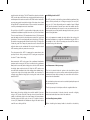
INSTALLATION MANUAL
B-BAND A2.2 XOM™ ONBOARD PREAMP WITH B-BAND UST AND
AST TRANSDUCER
This is a basic installation manual and tip sheet. For more information,
technical support, and pictures of installations about all B-Band products
please check the B-Band website at www.b-band.com or contact your
B-Band dealer, distributor or B-Band directly.
23-08-2007
DEAR CUSTOMER,
Thank you very much for purchasing this state-of-the-art
B-Band® acoustic transducer system. B-Band takes care to
provide the highest quality product and is manufactured and
supported in true spirit of acoustic instrument aficionados.
The outstanding sound reproduction of B-Band transducers is
based on the technology of a very special, worldwide-patented
material that is exclusive to B-Band. This material is very different from, and has nothing to do with, piezo-electric films
or transducers.
How is it different? We could write a long story here about the
technical characteristics of the material, like how the “microscopic lens-like gas bubbles”™ work inside the permanently
charged film, but the most important difference is the sound.
Whereas piezo pickups tend to impart a sound of their own
(often described as “quacky” or “plastic”), B-Band transducers act in much the same way a condenser microphone does.
B-Band systems will provide an excellent reproduction of your
instrument’s unique sound.
All of us at B-Band truly hope you enjoy this product.
Please contact us if you have any comments about B-Band
products.
Always ready to help you.
Yours sincerely,
Heikki Räisänen, CEO
B-Band Ltd
1. SAFETY AND PRODUCT CAUTIONS
Although B-Band products could be easy to install by following
these instructions carefully and checking the B-Band website
and references, we highly recommend the installation be done
by a professional qualified guitar craftsman or technician. Some
installations require a high knowledge about woodworking and
guitar structure.
B-BAND LTD AND B-BAND, INC. WILL NOT BE RESPONSIBLE
FOR ANY DAMAGES, PERSONAL INJURIES OR LIABILITIES
RESULTING FROM INSTALLATIONS, IMPROPERLY DONE INSTALLATIONS OR MISUSE OF PRODUCT.
Read all of these instructions closely before starting installation.
B-Band transducers (UST and AST) work with all B-Band Aseries preamps.
Do not cut, pull, crimp or bend at a sharp angle any B-Band
transducers.
B-Band UST and AST CANNOT be shortened or altered in any
way. This will cause audible hum and void the warranty.
Long-time exposure of UST or AST to high temperatures (over 50
°C / 120 °F) may reduce the output level permanently.
B-Band transducers will only work with B-Band preamps. B-Band
preamps will work with most any external audio preamps, mixers,
and instrument amplifiers.
ment in heavy conditions, for example, with freight companies or
airlines, to avoid possible damage to the instrument.
When doing any drilling, sawing, cutting or routing at the guitar,
be sure to secure the guitar so it will not move when doing
such work.
2. OVERVIEW OF B-BAND UST AND AST TRANSDUCERS
Both the B-Band UST (Under-Saddle Transducer) and AST
(Acoustic Soundboard Transducer) use the same-patented
transducer technology.
They are very flexible, but you should never pull or bend them
at a sharp angle.
B-Band transducers themselves do not require electrical power,
as they are permanently charged electrets. Because of the very
high output impedance (typical for condenser microphones) BBand UST and AST always require a B-Band preamp.
Standard piezo preamps will not work properly with B-Band transducers. They will produce low output and poor bass response.
The active portion of the B-Band UST transducer is 80 mm
(3.15”) from the end of the transducer at the opposite side of
the connector. The active portion of the 1470 AST is the 14 x 70
mm (.55” x 2.75”) area that attaches to the guitar. The rest of the
UST and the “lead” wire of the AST are not active. However, for
best performance always keep the inactive portion of either UST
or AST pickup from touching each other, or touching or rubbing
on the inside of the guitar, or touching the battery or output jack
wires. These can produce unwanted handling noise.
Before installation make sure instrument is in good working
condition.
Do not mount battery holder to preamp.
Even with the battery secure in the holder or the battery box lid
closed, the battery could get loose when transported. We strongly
recommend removing the battery before transporting the instru-
UST and Model sizes
Saddle width: 2.3 – 2.9 mm (.090” - .115” (3/32”))
B-Band model #: 22R
UST width: 2.3 mm (.090” (3/32”))
Saddle width: 3.0 mm (.118” (1/8”)) or more
B-Band model #: 29R
UST width: 3.0 mm (.118” (1/8”))
For operation of the A2.2 see the User’s Guide at the end of
these instructions.
3. OVERVIEW OF A2.2 PREAMP WITH XOM
4. PACKAGE CONTENTS
The A2.2 is an onboard preamp with a remote soundhole control
panel that has a volume and XOM mix control. This dual input
/ mono output preamp works only with B-Band UST and AST
pickups. Both inputs have input gain controls at the preamp box
and are accessible with a small screwdriver trough the holes at
the top of the preamp. These input gain controls help balance
the sound of the two pickups.
Note!
In the USA, transducers and preamps are packaged together. Everywhere else preamps and pickups are packaged separately.
4.1 UST package contents:
• 1 pc UST transducer
4.2 AST package contents:
• 1 pc AST transducer
• 1 pc cardboard installation guide (only AST)
All B-Band A-series preamps are designed to give optimum
performance with B-Band UST and AST transducers. The main
criterion in designing these preamps was to deliver studio quality
and user-friendly electronics to the diverse needs of acoustic
instrument musicians.
4.3 A2.2 package contents:
• 1 pc A2.2 preamp circuitry board
• 1 pc A2.2 preamp box
• 1 pc A2.2 preamp box back
• 1 pc remote control panel with volume and mix control and attached ribbon cable
• 1 pc output cable with endpin jack and strap attachment
• Strap attachment includes:
- Small hex nut
- Small dress washer
- Lock washer
- Large dress washer
- Large hex nut
• 1 pc battery holder with adhesive
• 1 pc battery cord harness (length 15 cm / 5.90”)
• 2 pcs wire clips
• 1 pc adhesive for the preamp
• 1 pc instructions and user guide
The A2.2 has the HzzLess® circuit for outstanding low noise
and high output.
The A2.2 has the XOM cross-over-mix circuit. The XOM system
combines the best aspects of each pickup into one complete
source. By sensing the guitar from two separate locations and
combining what each pickup does best, the XOM system has a
very rich and complex sound that further augments the already
superior sounding B-Band pickups.
The ideal process for authentic acoustic sound comes from combining the high frequencies of the AST and the low frequencies
of the UST, making a sound that is much more complex, true and
pure. In addition, the XOM pan pot allows the player to select
between UST / AST mix and the UST alone or one of the many
possibilities in-between for unlimited possibilities.
The A2.2 uses a standard 6.3 mm (1/4”) plug at the output jack.
There is a switch inside the output jack and the A2.2 battery power
is turned-on when a plug is inserted to turn on the 9-volt power.
For longer battery life unplug when not in use.
5. TOOLS AND MATERIALS NEEDED FOR INSTALLATION
• Drill, preferably with continuously variable speed
• Wood or metal drill bit, 2.3 mm (.09”) or 3 mm (.12”) depend
have smaller a bridge plate than others and the AST may be too
large to fit in front of the pins. In this case the AST can be installed
behind the bridge pins. If the bridge plate does not extend enough
behind the pins, it can be installed on the top of the guitar, right
next to the bridge plate. When installed behind the bridge pins
you will hear more of the "top" of the guitar when the balance
is turned to UST / AST XOM position. This may be desirable for
any steel string installation.
ingon the width of the transducer
• Wood or metal drill bit, 3 mm (.12”)
• Screwdriver, Posidriv #1
• Endpin reamer, 12 mm (.47”) or wood drill bit, 12 mm (.47”)
• Allen wrench, 2 mm (.08”)
• Punch (spike)
• 13 mm (.51”) wrench to tighten the nuts on the preamp
endpin jack
• Small hand-held mirror
• Flashlight (penlight)
• Small round file
• Masking tape
• 1470 AST cardboard installation mounting guide (supplied)
For classical guitars the installation the AST is done by hand
without the guide. For most classical guitars the AST is placed
inside the guitar parallel to center brace that runs parallel to the
strings on the bass strings side at the area between the bridge
and soundhole. Sometimes there is also a flat brace running
6. PREPARING THE GUITAR FOR INSTALLATION
Please read completely before starting the actual procedure.
6.1 Test fitting AST
For test fitting 1470 AST (if applicable), loosen and remove the
strings from the tuning machines.
Before removing the strings and bridge pins from the bridge
check to see if the AST will fit at the bridge plate correctly. Also
at this time, clean the bridge plate surface with a moist cloth
and let dry completely.
The cardboard installation template for the 1470 AST is specifically made for bridges that the saddle is at a slight angle to the
bridge pinholes. It may also be that the guide is too long for
the space. If so, the template can be trimmed with scissors
slightly to accommodate this. If in case the template still does
not work the transducer may be installed by hand. Although the
instructions do not specify how to do this, if you carefully read
the instructions you will be able to adapt them to perform the
installation by hand. It really is not that hard or critical to install
if you are careful.
Alternative AST installation for steel string guitars: Some guitars
6.2 Drilling hole for UST
parallel under the bridge. The AST should be placed so that the
AST is on the bass side of the brace running parallel to the strings
and that part of the active area of the AST, that has the lead to the
preamp, goes on the brace for the bridge. If the brace there is too
tall put the AST in front of the brace. Please read the instructions
carefully and adapt them to the installation.
For UST check the inside of the guitar to find the position of the
braces. Drill a preferably 30 - 45 degrees angled, 2.3 mm (.09”)
or 3 mm (.12”) hole (depending on the model of your B-Band
UST) for the transducer into the one end of the saddle slot. Be
careful not to damage the braces! In case you cannot make the
hole angled, because of possible damage to the braces, you can
make it straight down.
To test fit the 1470 AST in a guitar with a bridge plate, take the
cardboard installation template from the tray in the box. Note!
There is a small 4.5 mm (.18”) round and a 4.5 mm (.18”) elongated
part that both need to be punched out to make their respected
guide holes. The 4.5 mm round guide hole is for the low “E” bridge
pin and the elongated guide hole to fit at the high “E” bridge pin
inside the guitar. Peel away the protective covers from the two
adhesive dots on the cardboard. Do not peel away the actual
AST mounting adhesive protective cover yet!
It is very important to smooth the edge of the hole using a bit
of rolled sandpaper or a small file, to avoid pinching the UST as
the saddle lies on it. For A3T preamp you must drill the hole at
the low-E string side of the slot.
The placement of the AST is important for connection to the
preamp. For the A2.2 preamp, the AST’s lead goes away from
the low “E” side of the bridge.
Now mount the AST to the top of the cardboard installation
template at the rectangle AST area inscribed on the cardboard.
Now put the assembly to the bridge pins, with the AST towards
the bridge plate and check the fit. All of the AST’s active area
must fit at the soundhole side of the bridge plate without hanging over the edge of the bridge plate. Make sure that there is
enough space that the bridge pins or string ball-ends will not
touch the AST.
6.3 Placement of A2.2 preamp
The A2.2 is placed inside the guitar at the back of the guitar
and so that you can see the preamp, and so that the input gains
controls at the top of the preamp, are accessible with a screwdriver from the soundhole.
Be sure that the placement can be reached by both pickups and
by the output jack wire.
Adhesive side
The A2.2 preamp is held in place with the supplied adhesive.
Once the correct place is found, clean the area with a slightly
moist cloth and attach one side of the adhesive.
Next remove the strings, bridge pins and the saddle. If you are
using a UST, check that it fits into the slot easily and that the
saddle is sufficiently tight in the slot. Remove the strap button.
Carefully enlarge the hole using 12 mm (.47”) endpin reamer or
12 mm (.47”) wood drill bit. Smooth the edge of the hole with a
small file or a sinking drill bit.
6.4 Installing battery holder
Before installing the battery holder it should be checked by
inserting a 9-volt battery in and out of it to learn how it works.
Once this is checked, find a convenient place inside the guitar
where the battery holder can be reached and that there is good
access to the snap. Also check that it is in a place that the battery
can be put in and out easily.
small holes on each connector of the transducer and battery
cable harness should point upwards. If UST or AST is connected
improperly a loud audible hum will occur. Make sure that they
are connected correctly.
7.1 Installing the remote control board ribbon wire
Recommended places are at the neck block or at the back of
the guitar.
At the circuit board of the preamp and the remote control there
is a locking connector for the ribbon wire that connects to both.
With two fingers, pull the lock to open. One end at a time, insert
the ribbon with the writing on the ribbon facing up facing to the
slot in the locks at the circuit and then the remote control. Do not
force! Push the lock closed while holding the ribbon in place.
Be sure that the entire adhesive surface will make full contact
with surface you are attaching it to. Clean the surface with a
moist cloth and let the moist dry completely. Remove the protective liners of the adhesive and install it. Press firmly for about 30
seconds to make it secure. It takes 72 hours for the adhesive to
achieve its final holding ability.
When transducer, battery wire and output cable are connected
to preamp, close the cover and insert and tighten the four
screws.
7. CONNECTING THE TRANSDUCERS AND WIRES TO THE
PREAMP.
Turn the input gain controls fully clockwise- all the way up.
Check the circuit board of the preamp and see the picture
at these instructions for connections. Connect the transducer,
battery cable harness and the output cable. Notice that the
It is recommended to test the systems operation at this point.
Before you do this, make sure that the input gains are turned
fully clockwise- all the way up. Insert a battery and connect the
output cable to amplifier. You should hear it from the amplifier
when you tap on the transducer.
AST gain UST gain
AST
UST
Ribbon wire
Battery wire
Output wire
9. INSTALLING THE TRANSDUCERS AND REMOTE
CONTROL
8. INSTALLING THE PREAMP
For the next portion of the installation, be careful not to catch
the pickup on anything as you work; inadvertent tugging may
cause damage to the transducers or pull the connectors off the
pin headers at the preamp.
Install the UST up from inside the guitar through the hole in the
saddle slot. It is easier to find the hole inside the guitar if you
insert a small screwdriver or toothpick from the top through the
hole as a guide. Fit the UST all the way to the other end and
bottom of the slot. Then put the saddle in place.
Regarding AST, please note to lift one corner of the protective
layer of the mounting adhesive so it is easier to remove later.
Take the preamp assembly inside the guitar and install it to its
place. Let the transducer(s) and wire harnesses hang loose inside
the guitar at this moment.
At the output jack unscrew the strap attachment, the small nut
and the small dress washer from the endpin jack. Make sure
that the large nut; lock washer and large dress washer are
threaded onto the jack almost all the way to the opposite end of
the output of the jack.
Next, test-fit the jack the endpin hole. It is easier to install the
output jack by using an ink pen (or something similar) that fits
into the jack. Put the pen through the hole at the guitar where
the jack will go and with the other hand holding the output jack,
and that going through the sound hole, put the jack on the pen
and guide it through the hole of the guitar. Adjust the large nut
so that only the smaller threaded section comes almost entirely
out of the guitar. Put the dress washer and the small nut onto the
threads outside the guitar. Tighten securely using an appropriate wrench. Prevent the jack from rotating during tightening by
inserting a small Allen wrench into the holes of the end of the
jack. Install the strap attachment. Be careful not to over-tighten
it, it just needs to be snug. Connect a fresh 9-volt battery to the
snap-in connector and put it in the battery holder. Attach the
battery wires to the side of the guitar with the cord clamps. Roll
the extra cord as a “coil” in some of the clamps if necessary.
For installation of the 1470 AST (steel string guitars; x-braces),
place two bridge pins in their holes, one at the low “E” string
side and one at the high “E” side. Set the bridge pins normally.
This, with the cardboard installation template / AST assembly
will guide the AST to fit correctly. Having the AST cardboard
installation template / AST assembly lying on the bottom of the
guitar, remove the adhesive protective layer from the AST. Lift the
assembly up and guide the assembly so the bridge pins insert the
guide holes and carefully place it to the bridge plate. Then stick
it firmly by holding and pressing firmly with fingers for a short
while. Next carefully remove the cardboard installation template.
Make sure the AST fits there tight and secure.
Inside the guitar, make sure that the UST and AST leads do not
touch anything. We do not recommend attaching the “lead”
wires of the UST or AST to the guitar by any means. This may
cause excessive handling noise and resonance that sounds
like distortion.
For AST remove the adhesive protective layer from the AST.
Then stick it firmly by holding and pressing with fingers for a
short while. If necessary, you can remove the AST shortly after
attaching, but be careful when doing this. Carefully lift under
the edge of the AST, with your fingernail, and work it off slowly.
Don’t attempt to lift the AST off by pulling on the transducer
lead. Peel the adhesive off the wood, rather than peeling the
pickup off the adhesive. At installation this can be removed and
reattached two or three times.
Note! After 24 hours the adhesive will dry and it will be hard to
remove. Removal after this time may damage the pickup.
Now install the remote control. The preferred placement is at
the low E string side at the inside of the soundhole. It should be
positioned so that the wheels of the volume and mix control stick
out from the edge of the soundhole. The remote control panel
should fit on a flat surface. Clean the surface with a slightly moist
cloth and let dry before installing. Remove the tape cover at the
control panel and stick it.
Test the system before putting on the strings. To do this, plug into
an amplifier and then tap lightly on the top of the guitar to make
sure that you can hear the transducer when you tap. Another
good test is to shake the guitar when plugged into amplifier.
If anything is loose or if the transducer’s leads are touching
something you will hear it. This should not happen.
Install the strings and test the system. Now play, keep it real
and enjoy!
Using double stick tape, stick this first 5 mm (.20”) of the lead
to the guitar.
10. TROUBLE SHOOTING
10.1 No sound at all or intermittent sound
• Check the guitar cable and amplifier / mixer you are using.
• Check that the battery is not discharged. If the sound is noisy
or distorted, replace the battery.
• Check that the transducer and battery connectors are
inserted onto the pin headers of the preamp correctly.
• Check that the plug is making good connection with the out put jack. It may be so that the output jack is not sticking out
far enough when the strap button is on. To check, unscrew
the strap button off and plug in to the jack. If the symptoms
go away the output jack needs to be removed and the nuts
adjusted so the jack sticks out further.
• Check that both input gains are turned fully clockwise- all
the way up.
• Check that the ribbon wire form the remote control is in serted correctly. If it feels or looks like it is not connected
properly- unlock and re-install.
10.4 Imbalance, one or several strings sound louder or
quieter than the others (with UST)
If there’s only a very slight imbalance, let the saddle “shape” on
the UST for a few days. The fault may be repaired on its own. Users
have reported that after three (3) days the saddle has settled on
the UST and the balance becomes perfect.
10.5 Possible reasons for imbalance:
• The saddle or the bottom of the saddle slot is not flat.
• The saddle fits too loosely in its slot.
• The saddle slot might be too tight for the saddle to go in all
the way. Try pushing on the saddle firmly to seat the saddle
all the way down on the transducer.
• The saddle is too short.
• There is debris in the saddle slot.
• The angle of some of the strings behind the saddle is too low
or too high.
• The top of the guitar is bent.
• The pickup is not installed all the way to the end of the
saddle slot.
• If the material of the saddle is bone.
10.2 Loud hum
• Check to see that the connectors of the UST / AST are
inserted with the two holes up. If these connectors are up side down the system will work but it will buzz.
• Check that the connectors are inserted correctly onto their
pin headers at the preamp.
Bone is a natural material and the density and grain may not be
consistent. This may cause inconsistencies in the way the sound is
distributed making some strings louder or softer than others. We
highly recommend a manmade material for the saddle.
10.3 Resonance or distortion with some played notes.
There are a couple places where a resonance can typically occur with some notes, causing distorted-sounding output. First,
check that the lead portion of the transducer to the preamp is
not touching anything and that the battery or output wires are
not loose and thus cause resonance.
10.6 If the balance problem does not disappear on its own,
do the following:
• Check there is no debris in the saddle slot.
• Check the bottoms of both the saddle slot and saddle. They
should be flat and straight. It is common that the guitar top
“lives” and moves and because of this the saddle slot could
become curved, not straight. This may happen especially during
transport or by change of season when the humidity changes.
By making the saddle flexible, as in picture, these problems
can be greatly avoided.
• Check saddle is not loose in its slot. The saddle should be so
With the UST, another place, which in some cases has caused
resonance, is the UST hole from the saddle slot to the inside of
the guitar. Using a soft padding in it has cured these problems
effectively.
With the AST, if resonance is occurring, it may be coming form
the first 5 mm (.20”) of the “lead” wire coming from the AST.
10
problem is due to unequal pressure distribution, not bad mechanical contact. In this case, add the paper underneath the
louder strings. Try this as the last choice because it is very time
consuming and not so efficient.
tight that you cannot pull it away with your fingers.
• Check string angles behind the saddle. They should be about
the same behind every string. If the angle is too low, the string
will not put enough pressure on the transducer and that may
cause balance problems - usually higher output from the corresponding string. To deepen the angle, you can, for example,
file a wedge-shaped groove on the bridge pinhole so that
the string will have deeper angle behind the saddle (see the
next picture).
• On some instruments the outer most strings are too close to
the edge of the saddle, causing balance problems to these
strings. It may happen that the E string at the end of the UST
does not come as loud as other strings. In this case, make
another, shallow hole (not all the way through) at that end of
the saddle cavity and move the pickup so the tip of the UST
goes in the hole. If nothing else helps, you should machine the
saddle slot longer and use a new longer saddle.
• Balance problems may also occur with some string sets, for
example with classical guitars the G-string may cause prob lems.
10.8 Other problems
If you notice any other problems, please contact the dealer,
distributor or manufacturer, for help.
11. CUSTOMER FEEDBACK
If you have any comments, positive or negative, about any B-Band
product, please do not hesitate to contact B-Band.
12. A2.2 SPECIFICATIONS
S/N ratio: Greater than -90 dB
Distortion: 0.05 %
Frequency response: 50 Hz - 40 kHz (-3 dB)
Low-cut slope: 24 dB/octave
Voltage gain: AST channel, +15 - +30 dB;
UST channel, +15 - +30 dB
Input impedance (both channels): 50 Mohm || < 10 pF
Output impedance: < 3 kohm
Nominal output level: -10 dB u (0.245 Vrms)
Power supply: 9-volt battery (not included)
Current consumption: 2 mA typical
Connections: Transducer inputs, 2.54 mm / .10” header; Output,
6.3 mm / 1/4” jack
Weight (with accessories): 45 g
Dimensions: L 42 mm / 1.65”, W 32 mm / 1.26”, H 15 mm / 0.6”
10.7 If all things mentioned above are correct, and there still
is a balance problem, you should try the following tricks:
• The easiest way is to install a spacer, made of soft wood,
underneath the saddle or underneath the UST. The proper
thickness is 0.5 - 0.8 mm (.02” - .03”). This will cure imbal ance problems effectively.
• A very efficient way is to make the saddle more flexible by
modifying it, for example see picture below. Even more efficient it is to cut the saddle into six separate pieces, or to cut
it almost through between the strings but leave just a small
portion on the bottom side of the saddle, i.e. cut it from the
bottom towards the top.
• Most of the balance problems are due the fact that the guitar
top lives. By making the saddle flexible, these problems can
be greatly avoided.
• If anything else does not help, you can try to add one or two
layers of ordinary letter paper under the saddle, underneath
the quieter strings. This will cause a better mechanical contact
between the saddle and the UST and thus increase the volume.
If the volume decreases when adding the paper, the balance
13. EU / DECLARATION OF CONFORMITY
This B-Band product has been designed, manufactured and
tested to comply with the requirements of EMC directive 89/336/
EEC and CE mark directive 93/68/EEC and carry the CE marking accordingly.
11
LED’s in this product are Class 1 in accordance to
EN 60825-1.
A2.2 USER GUIDE
Before plugging in become familiar with the controls.
Statement of EU Declaration of Conformity is available from
manufacturer upon request.
With the guitar in playing position- on your lap – feel for the
wheels of the control panel at the soundhole. The control that is
closer to the fret board is the volume. The control closer to the
bridge is the XOM mix control.
XOM MIX CONTROL
VOLUME
XOM
UST
BRIDGE
INCREASE
SOUNDHOLE
FRET BOARD
The volume is increased when that control is turned towards the
bridge and decreased in the opposite direction.
The A2.2 has the XOM mix control. When the mix control is turned
all the way towards the fret board, this is the XOM position- a 50
/ 50 mix of AST and UST is heard. This is the crossover mix of the
AST and UST. The crossover point is 800 Hz. From 800 Hz and up
is AST. 800 Hz and down is the UST. 50% is the high tones of the
AST and 50% is the low tones of the UST. See diagram below.
12
B-BAND LIMITED WARRANTY STATEMENT
MIX CONTROL
CENTER BLEND
UST
SIDE OF MIX CONTROL
XOM
In the unlikely event that your product needs guarantee service,
please contact your dealer, distributor or manufacturer. To avoid
any unnecessary inconvenience on your part, we recommend
you read this instruction manual carefully before seeking guarantee service.
SIDE OF MIX CONTROL
AST
UST
YOUR GUARANTEE
FULL RANGE UST
800 Hz
CROSSOVER
POINT
By this Guarantee, B-Band guarantees the product to be free
from defects in materials and workmanship at the date of original
purchase for a period of one (1) year from that date.
50 / 50 MIX OF AST & UST
If within the guarantee period the product is determined to be
defective (at the date of original purchase) due to improper
materials or workmanship, B-Band will, without charge for labor
or parts, repair or (at B-Band’s discretion) replace the product
or its defective parts subject to the terms and limitations below.
B-Band may replace defective products or parts with new or
refurbished products or parts. All products and parts replaced
become the property of B-Band.
When the mix control is turned all the way towards the bridge
the sound is ONLY the UST pickup sound. Full range sound of
the UST. No AST sound.
With the mix control at any position you always hear the low tone
part of the UST pickup. This provides a very round and solid low
tone sound at any position.
The XOM mix control blends the higher tone sounds of both the
UST and AST.
TERMS
1. Guarantee services will be provided only if the original invoice
or sales receipt (indicating the date of purchase, model name
and dealer’s name) is presented with the defective product
within the guarantee period. B-Band may refuse free-of-charge
guarantee service if these documents are not presented or if they
are incomplete or illegible. This Guarantee will not apply if the
model name or serial number on the product has been altered,
deleted, removed or made illegible.
Before plugging in the A2.2 make sure that the volume is turned
OFF and the XOM mix control is at the UST side. The amp or mixer
should be OFF, volume turned OFF and EQ setting at flat or OFF.
Plug into the amp or mixer and then plug into to the A2.2. Turn
the amp or mixer ON. Turn the volume up at the amp or mixer
to about “10 o’clock”. Slowly turn the A2.2 volume up, now you
should hear The UST pickup.
2. This Guarantee does not cover transport costs and risks associated with transport of your product to and from B-Band.
Next experiment with how the XOM mix control works. Once a
sound that you like is found, you can further experiment with the
EQ at the amp or mix to fine tune the sound.
3. This guarantee does not cover:
a) periodic maintenance and repair or parts replacement due
Enjoy!
13
to wear and tear.
b) consumables (components that are expected to require periodic replacement during the lifetime of a product)
c) damage or defects caused by use, operation or treatment of
the product inconsistent with normal use
d) damage or changes to the product as a result of:
i. misuse, including:
- treatment resulting in physical, cosmetic or surface damage or
changes to the product
- failure to install or use the product for its normal purpose or in
accordance with B-Band’s instructions on installation or use
- failure to maintain the product in accordance with B-Band’s
instructions on proper maintenance
- installation or use of the product in a manner inconsistent with
the technical or safety laws or standards in the country where
it is installed or used
ii. the condition of or defects in systems with which the product
is used or incorporated except other B-Band’s products designed
to be used with the product
iii. use of the product with accessories, peripheral equipment
and other products of a type, condition and standard other than
prescribed by B-Band
iv. repair or attempted repair by persons who are not B-Band
employees
v. adjustments or adaptations without B-Band’s prior written
consent, including:
- upgrading the product beyond specifications or features described in the instruction manual, or
- modifications to the product to conform it to national or local technical or safety standards in countries other than those
for which the product was specifically designed and manufactured
vi. neglect
vii. accidents, fire, liquids, chemicals, other substances, flooding,
vibrations, excessive heat, improper
ventilation, power surges, excess or incorrect supply or input
voltage, radiation, electrostatic discharges including lighting,
other external forces and impacts.
EXCLUSIONS AND LIMITATIONS
EXCEPT AS STATED ABOVE, B-BAND MAKES NO WARRANTIES
(EXPRESS, IMPLIED, STATUTORY OR OTHERWISE) REGARDING
PRODUCT PERFORMANCE, ACCURACY, RELIABILITY, FITNESS
FOR A PARTICULAR PURPOSE, OR OTHERWISE. If this exclusion is not permitted or fully permitted by applicable law, B-Band
excludes or limits its warranties only to the maximum extent
permitted by applicable law. Any warranty that cannot be fully
excluded will be limited (as far as permitted by applicable law)
to the duration of this Guarantee.
B-BAND’S ONLY OBLIGATION UNDER THIS GUARANTEE IS TO
REPAIR OR REPLACE PRODUCTS SUBJECT TO THESE GUARANTEE TERMS AND CONDITIONS. B-BAND IS NOT LIABLE FOR
ANY LOSS OR DAMAGE RELATING TO PRODUCTS, SERVICE,
THIS GUARANTEE OR OTHERWISE, INCLUDING - ECONOMIC
OR INTANGIBLE LOSSES – THE PRICE PAID FOR THE PRODUCT
- LOSS OF PROFITS, REVENUE, DATA, ENJOYMENT OR USE OF
THE PRODUCT OR ANY ASSOCIATED PRODUCTS - INDIRECT,
INCIDENTAL OR CONSEQUENTIAL LOSS OR DAMAGE. THIS
APPLIES WHETHER THAT LOSS OR DAMAGE RELATES TO:
IMPAIRED OR NON-OPERATION OF THE PRODUCT OR ASSOCIATED PRODUCTS THROUGH DEFECTS OR UNAVAILABILITY
WHILE WITH B-BAND, WHICH CAUSED DOWNTIME, LOSS OF
USER TIME OR BUSINESS INTERRUPTION INACCURACY OF
OUTPUT FROM THE PRODUCT OR ASSOCIATED PRODUCTS.
THIS APPLIES TO LOSS AND DAMAGES UNDER ANY LEGAL THEORY, INCLUDING NEGLIGENCE AND OTHER TORTS,
BREACH OF CONTRACT, EXPRESS OR IMPLIED WARRANTY,
AND STRICT LIABILITY (EVEN WHERE B-BAND HAS BEEN
ADVISED OF THE POSSIBILITY OF SUCH DAMAGES).
Where applicable law prohibits or limits these liability exclusions,
B-Band excludes or limits its liability only to the maximum extent
permitted by applicable law. For example, some countries prohibit
the exclusion or limitation of damages resulting from negligence,
gross negligence, willful misconduct, deceit and similar acts. BBand’s liability under this guarantee will in no case exceed the
price paid for the product, but if applicable law permits only higher
4. This guarantee covers only hardware components of the
product.
14
liability limitations, the higher limitations apply.
YOUR LEGAL RIGHTS RESERVED
Consumers have legal (statutory) rights under applicable national
laws relating to the sale of consumer products. This guarantee
does not affect statutory rights you may have nor those rights
that cannot be excluded or limited, nor rights against the person
from whom you purchased the product. You may assert any rights
you have at your sole discretion.
15
International:
B-Band Ltd
Konttisentie 8, 02150 Vaajakoski, Finland
Tel: +358 14 332 9050
Fax: +358 14 332 9001
Email: sales@b-band.com
Internet: www.b-band.com
USA:
B-Band, Inc.
10909 Vanowen Street, Suite 300
North Hollywood, CA., 91605, USA
Tel: (818) 508 9412
Fax: (818) 508 9413
Email: sales@b-bandusa.com
Internet: www.b-band.com
B-Band, B-Band logo, A2.2, XOM, UST, AST, HzzLess and “microscopic lens-like gas bubbles” are either registered trademarks or trademarks of B-Band Ltd in the United States and
/ or other countries. Patented, patents pending. List of patents are available from B-Band
Ltd upon request. All specifications are subject to change without prior notice. All rights
reserved. Copyright © 1996-2007 B-Band Ltd.
16