1
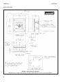
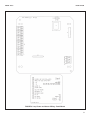
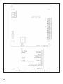
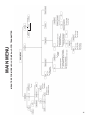
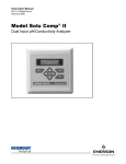
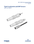
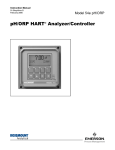
Instruction Sheet
PN 51A-Xmt-P-FF-FI/rev.F
October 2010
Model Solu Comp™ Xmt-P-FF/FI
FOUNDATION® Fieldbus Two-Wire
pH/ORP Transmitter
For additional information, please visit our website at
www.emersonprocess.com/raihome/liquid/.
ESSENTIAL INSTRUCTIONS
READ THIS PAGE BEFORE PROCEEDING!
Your purchase from Rosemount Analytical, Inc. has resulted in one of the finest instruments available for your
particular application. These instruments have been designed, and tested to meet many national and international standards. Experience indicates that its performance is directly related to the quality of the installation
and knowledge of the user in operating and maintaining the instrument. To ensure their continued operation to
the design specifications, personnel should read this manual thoroughly before proceeding with installation,
commissioning, operation, and maintenance of this instrument. If this equipment is used in a manner not specified by the manufacturer, the protection provided by it against hazards may be impaired.
• Failure to follow the proper instructions may cause any one of the following situations to occur: Loss of life;
personal injury; property damage; damage to this instrument; and warranty invalidation.
• Ensure that you have received the correct model and options from your purchase order. Verify that this manual covers your model and options. If not, call 1-800-854-8257 or 949-757-8500 to request correct manual.
• For clarification of instructions, contact your Rosemount representative.
• Follow all warnings, cautions, and instructions marked on and supplied with the product.
• Use only qualified personnel to install, operate, update, program and maintain the product.
• Educate your personnel in the proper installation, operation, and maintenance of the product.
• Install equipment as specified in the Installation section of this manual. Follow appropriate local and national
codes. Only connect the product to electrical and pressure sources specified in this manual.
• Use only factory documented components for repair. Tampering or unauthorized substitution of parts and
procedures can affect the performance and cause unsafe operation of your process.
• All equipment doors must be closed and protective covers must be in place unless qualified personnel are
performing maintenance.
• If this equipment is used in a manner not specified by the manufacturer, the protection provided by it against
hazards may be impaired.
WARNING
EXPLOSION HAZARD
DO NOT OPEN WHILE CIRCUIT IS LIVE
DO NOT RUB OR CLEAN WITH SOLVENTS
9241589-00/A
MODEL Xmt-P
SPECIFICATIONS
SPECIFICATIONS - GENERAL
Case: ABS (panel mount), polycarbonate (pipe/surface
ount). Both versions are NEMA 4X/CSA 4 (IP65).
Dimensions
Panel (code -10): 6.10 x 6.10 x 3.72 in. (155 x 155 x
94.5 mm)
Surface/Pipe (code -11): 6.23 x 6.23 x 3.23 in. (158
x 158 x 82 mm); see page 5 for dimensions of pipe
mounting bracket.
Conduit openings: Accepts PG13.5 or 1/2 in. conduit fittings
Ambient Temperature: 32 to 122°F (0 to 50°C). Some
degradation of display above 50°C.
Storage Temperature: -4 to 158°F (-20 to 70°C)
Relative Humidity: 10 to 90% (non-condensing)
Weight/Shipping Weight: 2 lb/3 lb (1 kg/1.5 kg)
Display: Two line, 16-character display. Character height:
4.8 mm; first line shows process variable (pH, ORP,
conductivity, % concentration, oxygen, ozone, chlorine, or monochloramine), second line shows process
temperature and output current. For pH/chlorine combination, pH may also be displayed. Fault and warning messages, when triggered, alternate with temperature and output readings.
During calibration and programming, messages,
prompts, and editable values appear on the two-line
display.
Temperature resolution: 0.1°C (≤99.9°C); 1°C (≥100°C)
Hazardous Location Approval: For details, see specifications for the measurement of interest.
RFI/EMI: EN-61326
Sira MC070113/00
Power & Load Requirements: A power supply voltage of
9-32 Vdc at 13 mA is required.
FUNCTIONAL SPECIFICATIONS
pH Range: 0 to 14
ORP Range: -1400 to +1400mV
Calibrations/standardization: The automatic buffer
recognition uses stored buffer values and their temperature curves for the most common buffer standards available worldwide. The transmitter also performs a
stabilization check on the sensor in each buffer.
A manual two-point calibration is made by immersing the
sensor in two different buffer solutions and entering the pH
values. The microprocessor automatically calculates the
slope which is used for self-diagnostics. An error message
will be displayed if the pH sensor is faulty. This slope can
be read on the display and/or manually adjusted if desired.
An on-line one-point process standardization is accomplished by entering the pH or ORP value of a grab sample.
Preamplifier Location: A preamplifier must be used to
convert the high impedance pH electrode signal to a low
impedance signal for transmitter use. The integral preamplifier of the Model Xmt-P may be used when the sensor
to transmitter distance is less than 15 ft (4.5 m). Locate
the preamplifier in the sensor or junction box for longer
distances.
Automatic Temperature Compensation: External 3 or 4
wire Pt 100 RTD or Pt 1000 RTD located in the sensor,
compensates the pH reading for temperature fluctuations.
Compensation covers the range -15 to 130°C (5 to 270°F).
Manual temperature compensation is also selectable.
Accuracy: ± 1 mV @ 25°C ± 0.01 pH
Repeatability: ± 1 mV @ 25°C ± 0.01 pH
Stability: 0.25% / year @ 25°C
Diagnostics: The internal diagnostics can detect:
Calibration Error
Sensor Failure
High Temperature Warning
CPU Failure
Low Temperature Warning
Input Warning
ROM Failure
Glass Warning
Glass Failure
Reference Warning
Reference Failure
Once one of the above is diagnosed, the display will show
a message describing the problem.
Digital Communications:
Fieldbus (pH): Four AI blocks assigned to pH, temperature, reference impedance, and glass impedance.
Fieldbus (ORP): Three AI blocks assigned to ORP,
temperature, and reference impedance.
Fieldbus (pH and ORP): Execution time 75 msec.
One PID block; execution time 150 msec. Device
type 4085. Device revision 1. Certified to ITK 4.5.
2
MODEL Xmt-P
SPECIFICATIONS
Intrinsic Safety:
Non-Incendive:
Class I, II, III, Div. 1
Class I, Div. 2, Groups A-D
Groups A-G
Dust Ignition Proof
T4 Tamb = 50°C
Class II & III, Div. 1, Groups E-G
NEMA 4/4X Enclosure
Class I, II, III, Div. 1
Groups A-G
Class I, Div. 2, Groups A-D
T4 Tamb = 50°C
Dust Ignition Proof
Class II & III, Div. 1, Groups E-G
ATEX
1180 II 1 G
Baseefa04ATEX0213X
NEMA 4/4X Enclosure
T4 Tamb = 50°C
EEx ia IIC T4
Tamb = 0°C to 50°C
PROCEDURE — QUICK STANDARDIZATION CALIBRATION
The pH measured by the transmitter can be changed to match the reading from a second or referee instrument. The
process of making the two readings agree is called standardization.
During standardization, the difference between the two values is converted to the equivalent voltage. The voltage, called
the reference offset, is added to all subsequent measured cell voltages before they are converted to pH. If after standardization the sensor is placed in a buffer solution, the measured pH will differ from the buffer pH by an amount equivalent to the standardization offset.
1. Install the pH sensor in the process liquid.
2. Once readings are stable, measure the pH of the liquid using a referee instrument.
3. Because the pH of the process liquid may change if the temperature changes, measure the pH of the grab sample
immediately after taking it.
4. For poorly buffered samples, it is best to determine the pH of a continuously flowing sample from a point as close as
possible to the sensor.
5. From the main display, press ENTER 3 times within 5 seconds.
6. The top line shows the present reading. Use the arrow keys to change the
pH reading in the second line to match the pH reading from the referee
instrument.
7. The screen at left appears if the entered pH was greater than 14.00 or if
the mV offset calculated by the transmitter during standardization exceeds
the reference offset limit programmed into the transmitter. The display then
returns to the main display. Repeat the standardization. To change the reference offset from the default value (60 mV), see section 7.4.
8. If the entry was accepted the display returns to the main display.
*Quick Standardization allows the Xmt-P-FF Fieldbus Transmitter to be standardized without the need to set the
Transducer Block to the Out of Service Mode. The measured pH status remains good and prevents any subsequent
function blocks linked to the Transducer Block from going to the Out of Service Mode, or exhibiting spurious block errors.
3
QUICK START GUIDE
FOR MODEL SOLU COMP Xmt-P-FF/FI TRANSMITTER
1. Refer to page 5 for installation instructions.
2. Wire pH or ORP sensor to the transmitter. See Figure 6 for panel mount; Figure 7 for pipe or surface mount. Refer
to the sensor instruction sheet for details.
3. Once connections are secure and verified, apply power to the transmitter.
4. When the transmitter is powered up for the first time, Quick Start screens appear. Using Quick Start is easy.
a. A blinking field shows the position of the cursor.
b. Use the ⇐ or ⇒ key to move the cursor left or right. Use the ⇑ or ⇓ key to move the cursor up or down or to
increase or decrease the value of a digit. Use the ⇑ or ⇓ key to move the decimal point.
c.
Press ENTER to store a setting. Press EXIT to leave without storing changes. Pressing EXIT also returns the
display to the previous screen.
English
Español
Français
>>
pH
Measure?
Redox
Sensor/JBox
7. Choose preamplifier location. Select Xmtr to use the integral preamplifier in the
transmitter; select Sensor/JBox if your sensor has an integral preamplifier or if
you are using a remote preamplifier located in a junction box.
8. Choose temperature units: °C or °F.
Temperature in?
°C
6. Choose measurement: pH, ORP, or Redox.
ORP
Use Preamp in?
Xmtr
5. Choose the desired language. Select >> to show more choices.
°F
9. To change output settings, to scale the 4-20 mA output, to change measurement-related settings from the default values, and to set security codes, press
MENU. Select Program and follow the prompts. Refer to the appropriate menu
tree (page 11).
10. To return the transmitter to default settings, choose ResetAnalyzer in the
Program menu.
4
MODEL Xmt-P
INSTALLATION
UNPACKING AND INSPECTION
Inspect the shipping container. If it is damaged, contact
the shipper immediately for instructions. Save the box. If
there is no apparent damage, unpack the container. Be
sure all items shown on the packing list are present. If
items are missing, notify Emerson Process Management
immediately.
INSTALLATION
1. Although the transmitter is suitable for outdoor use,
do not install it in direct sunlight or in areas of extreme
temperatures.
FIGURE 1. Removing the Knockouts
2. Install the transmitter in an area where vibrations and
electromagnetic and radio frequency interference are
minimized or absent.
3. Keep the transmitter and sensor wiring at least one
foot from high voltage conductors. Be sure there is
easy access to the transmitter.
4. The transmitter is suitable for panel (Figure 3), pipe
(Figure 4), or surface (Figure 5) mounting.
5. The transmitter case has two 1/2-inch (PG13.5) conduit openings and either one or four 1/2-inch knockouts. The panel mount Xmt-P-FF/FI has four knockouts. The pipe/surface mount transmitter has two
knockouts*. One conduit opening is for the power/output cable; the other opening is for the sensor cable.
Figure 1 shows how to remove a knockout. The
knockout grooves are on the outside of the case.
Place the screwdriver blade on the inside of the case
and align it approximately along the groove. Rap the
screwdriver sharply with a hammer until the groove
cracks. Move the screwdriver to an uncracked portion
of the groove and continue the process until the
knockout falls out. Use a small knife to remove the
flash from the inside of the hole.
(9 - 32 VDC)
6. Use weathertight cable glands to keep moisture out to
the transmitter. If conduit is used, plug and seal the
connections at the transmitter housing to prevent
moisture from getting inside the instrument.
7. To reduce the likelihood of stress on wiring connections, do not remove the hinged front panel (-11 models) from the base during wiring installation. Allow
sufficient wire leads to avoid stress on conductors.
FIGURE 2. Power Supply/Current Loop Wiring
*NEMA plug may be supplied instead of knockout for
pipe/surface version.
5
MODEL Xmt-P
INSTALLATION
Panel Mounting.
MILLIMETER
INCH
FIGURE 3. Panel Mount Installation
Access to the wiring terminals is through the rear cover. Four screws hold the cover in place.
6
MODEL Xmt-P
INSTALLATION
Pipe Mounting.
MILLIMETER
INCH
FIGURE 4. Pipe Mount Installation
The front panel is hinged at the bottom. The panel swings down for access to the wiring terminals.
7
MODEL Xmt-P
INSTALLATION
Surface Mounting.
MILLIMETER
INCH
FIGURE 5. Surface Mount Installation
The front panel is hinged at the bottom. The panel swings down for access to the wiring terminals.
8
MODEL Xmt-P
INSTALLATION
FIGURE 6. Loop Power and Sensor Wiring - Panel Mount
9
FIGURE 7. Loop Power and Sensor Wiring - Pipe/Surface Mount
10
11
MENU TREE FOR MODEL SOLU COMP Xmt-P-FF/FI TRANSMITTER
MAIN MENU
Language
SENSOR COMPATIBILITY CHART
pH/ORP SENSOR
320HP-58
328A
370
371
372
381 pHE-31-41-52
381+
385+
389-02-54 / 389VP-54
396-54-62 / 396VP
396P-55 / 396PVP-55
396R / 396RVP-54
397-54-62
398-54-62 / 398VP-54
398R-54-62 / 398RVP-54
399-09-62 / 399VP-09 / 399-14
Hx338
Hx348
TF396
The right people,
the right answers,
right now.
DIAGNOSTIC CAPABILITY
Glass only
Glass only
Glass only
Glass only
Glass only
Glass only
Glass and Reference
Glass and Reference
Glass only
Glass only
Glass and Reference
Glass and Reference
Glass only
Glass only
Glass only
Glass only
Glass only
Glass only
none
ON-LINE ORDERING NOW AVAILABLE ON OUR WEB SITE
http://www.raihome.com
Specifications subject to change without notice.
8
Credit Cards for U.S. Purchases Only.
Emerson Process Management
2400 Barranca Parkway
Irvine, CA 92606 USA
Tel: (949) 757-8500
Fax: (949) 474-7250
http://www.raihome.com
© Rosemount Analytical Inc. 2010