1
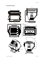
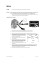
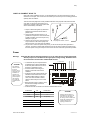
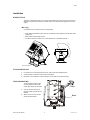
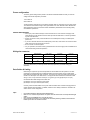
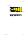
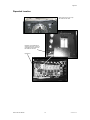
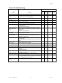
ART-575W Spectrum™ 575W USER MANUAL CHAUVET, 3000 N 29th Ct, Hollywood, FL 33020 U.S.A (800) 762-1084 – (954) 929-1115 FAX (954) 929-5560 www.chauvetlighting.com 2006-06-15/17:08 TABLE OF CONTENT TABLE OF CONTENT....................................................................................................................................................... 2 BEFORE YOU BEGIN....................................................................................................................................................... 3 WHAT IS INCLUDED .......................................................................................................................................................................................................... 3 UNPACKING INSTRUCTIONS .............................................................................................................................................................................................. 3 AC POWER ..................................................................................................................................................................................................................... 3 SAFETY INSTRUCTIONS .................................................................................................................................................................................................... 3 INTRODUCTION ............................................................................................................................................................... 4 TECHNICAL FEATURES ..................................................................................................................................................................................................... 4 FEATURES ....................................................................................................................................................................................................................... 4 DMX CHANNEL SUMMARY ............................................................................................................................................................................................... 4 PRODUCT OVERVIEW....................................................................................................................................................................................................... 5 SETUP .............................................................................................................................................................................. 6 LAMP............................................................................................................................................................................................................................... 6 Lamp installation................................................................................................................................................................................................. 6 Lamp Alignment How-To.................................................................................................................................................................................... 7 POWER ........................................................................................................................................................................................................................... 7 INSTALLATION .................................................................................................................................................................................................................. 8 Orientation .......................................................................................................................................................................................................... 8 Floor Mounting.................................................................................................................................................................................................... 8 Truss Mounting................................................................................................................................................................................................... 8 Power configuration ................................................................................................................................................................................................. 9 Wiring the connector................................................................................................................................................................................................ 9 Data Cables & Linking ............................................................................................................................................................................................. 9 OPERATING INSTRUCTIONS ........................................................................................................................................ 10 OPERATING MODES ....................................................................................................................................................................................................... 10 Master/Slave & Stand-Alone ............................................................................................................................................................................ 10 Accessing internal programs in Master mode.................................................................................................................................................. 11 Built-in Programs chart..................................................................................................................................................................................... 12 DMX Mode........................................................................................................................................................................................................ 13 Setting the starting address ............................................................................................................................................................................. 13 APPENDIX ...................................................................................................................................................................... 16 DMX PRIMER ................................................................................................................................................................................................................ 16 Fixture Linking .................................................................................................................................................................................................. 16 DMX CHANNEL VALUES ................................................................................................................................................................................................ 17 PHOTO METRICS ........................................................................................................................................................................................................... 18 DIPSWITCH LOCATION.................................................................................................................................................................................................... 19 MAINTENANCE ............................................................................................................................................................................................................... 20 RETURNS PROCEDURE .................................................................................................................................................................................................. 20 CLAIMS ......................................................................................................................................................................................................................... 20 GENERAL TROUBLESHOOTING ....................................................................................................................................................................................... 21 TECHNICAL SPECIFICATIONS .......................................................................................................................................................................................... 22 TECHNICAL SUPPORT .................................................................................................................................................................................................... 22 ART-575W User Manual 2 2006-06-15/17:08 BEFORE YOU BEGIN What is included ART-575W – Spectrum™ 575W (1) HSR575 HID lamp Power cord attached with bare ends Warranty Card & Manual Unpacking Instructions Immediately upon receiving a fixture, carefully unpack the carton, check the contents to ensure that all parts are present, and have been received in good condition. Notify the shipper immediately and retain packing material for inspection if any parts appear damaged from shipping or the carton itself shows signs of mishandling. Save the carton and all packing materials. In the event that a fixture must be returned to the factory, it is important that the fixture be returned in the original factory box and packing. AC Power To determine the power requirements for a particular fixture, see the label affixed to the back plate of the fixture or refer to the fixture’s specifications chart. A fixture’s listed current rating is its average current draw under normal conditions. All fixtures must be powered directly off a switched circuit and cannot be run off a rheostat (variable resistor) or dimmer circuit, even if the rheostat or dimmer channel is used solely for a 0% to 100% switch. Before applying power to a fixture, check that the source voltage matches the fixture’s requirement. Check the fixture or device carefully to make sure that if a voltage selection switch exists that it is set to the correct line voltage you will use. Warning! Verify that the internal multi-tap transformer is set to match the line voltage applied. All fixtures must be connected to circuits with a suitable Earth Ground. Safety Instructions Please read these instructions carefully, which includes important information about the installation, usage and maintenance? Please keep this User Guide for future consultation. If you sell the unit to another user, be sure that they also receive this instruction booklet. Always make sure that you are connecting to the proper voltage and that the line voltage you are connecting to is not higher than that stated on decal or rear panel of the fixture. To prevent risk of fire or shock make sure there are no flammable materials close to the unit while operating. The unit must be installed in a location with adequate ventilation, at least 50cm from adjacent surfaces. Be sure that no ventilation slots are blocked. Always disconnect from power source before servicing or replacing lamp or fuse and be sure to replace with same lamp source. Secure fixture to fastening device using a safety chain. Never carry the fixture solely by its head. Use its carrying handles. Maximum ambient temperature is Ta: 50°. Do not operate fixture at temperatures higher than this. In the event of serious operating problem, stop using the unit immediately. Never try to repair the unit by yourself. Repairs carried out by unskilled people can lead to damage or malfunction. Please contact the nearest Caution! authorized technical assistance center. Always use the same type spare parts. Don’t connect the device to a dimmer pack. Make sure power cord is never crimped or damaged. Never disconnect power cord by pulling or tugging on the cord. Avoid direct eye exposure to lamp while it is on. Check your power cables carefully to ensure that there are no cuts or breach of integrity of the outer shell at any point. Moisture could be drawn up inside the cable due to a vacuum generated by heat inside the fixture. Protect connectors for both power and data lines in a weatherproof housing or a weatherproof junction box. If you don’t hard wire the fixture to a weatherproof junction box, make sure to use an IP55 or better rated connector for both plugs and connectors. Do not connect to a dimmer system. For your protection, the fixture must be grounded and the AC mains supply must be outfitted with a circuit breaker and ground-fault protection. There are no user serviceable parts inside the unit. Do not open the housing or attempt any repairs yourself. In the unlikely event your unit may require service, please contact CHAUVET. ART-575W User Manual 3 2006-06-15/17:08 INTRODUCTION Technical Features 8-channel DMX-512 exterior color wash CMY color mixing system Vectored movement of all color blades for super smooth and slow transitions 11 instantly selectable preset color macros Variable mechanical dimmer (0 ~ 100%) Variable mechanical zoom (7°~40°) 32 built in color change programs at varying speeds Durable and weatherproof IP-54 rated housing Very low noise operation (convection cooled) <- look for a fan?? No control necessary, Master/Slave operation Frosted lens diffuser Micro-stepping motors Thermal switch protection Features DMX Channel Summary CHANNEL FUNCTION 1 Vector speed 2 Yellow 3 Magenta 4 Cyan 5 Color Macros 6 Dimmer 7 Zoom 8 Automatic ART-575W User Manual 4 2006-06-15/17:08 Introduction Product Overview 446 17.6in 445.7 17.5in 410 16.1in Front View 10.0in 16.9in 13.5in 12.8in 3.15in 528 20.8in 289.2 11.38in Side View 428 344 100 254 100 80 289.2 150 326 11.4in 5.9in 396 3.9in 15.6in Bottom View Top View 126 Carrying handles Projection angle ART-575W User Manual 5 2006-06-15/17:08 SETUP Lamp You will need to install a lamp prior to the initial operation of the fixture. Warning! When replacing the lamp, please wait 15 minutes after powering down to allow the unit to cool down! Always disconnect from main power prior to lamp replacement. Do not touch the envelope (glass area) of the bulb with bare hands. If this happens, clean the lamp with alcohol and wipe it with a lint free cloth before installation. L AM P I N ST AL L AT I O N C D E A B Lamp plate Follow this direction to open cover W a rn in g! Be sureto disconnect unit f rom power before Changing l amps or opening the unit cover. Lamp becomes hot during operation.allow time (at l east 15 minutes)to cool before handing.do not Look directly at l amp when l it. INSIDE Turn screwsA & B to adjust horizontal position. Turn screw C to adjust vertical position. Turn screws A, B & C clockwise to increase the diameter of the light beam. Turn screws A, B & C anti-clockwise to reduce thediameter of the light beam. Remove the l amp cover by turning screwsD & E A B D ON E OFF C POWER SWITCH Back cover plate 1) Remove the back cover plate by removing all 8 screws on the rear of the fixture. 2) Remove the screws (D) and (E) on the lamp plate. Pull out the lamp cover plate. 3) With lamp socket plate out and the lamp accessible, if replacing the lamp, remove old lamp first. 4) Holding the new lamp by its base, align the small pin on the lamp with the small hole in the socket and insert the lamp squarely until the retaining clips on the lamp socket secures the lamp tightly. 5) Clean the glass/envelope of the bulb with an alcohol wipe or equivalent. 6) Holding the lamp plate, insert the tip of the lamp into the fixture with extreme care. Navigate the lamp all the way until it reaches the reflector and the lamp base plate touches the bottom plate of the fixture. A D B Remove these screws to install or replace lamp E C Lamp plate 7) Align the screw holes and fasten the screws back onto the lamp plate. 8) Turn the fixture on and adjust the lamp alignment screws until the brightest most even area of the beam is in the center of your spot. It may be necessary for you to use a controller in order to command the fixture to display a white beam. Visit the “Lamp Alignement How-To” section in this manual for further reading and tips on the subject. 9) Place the back cover plate back on the fixture and screw on securely. ART-575W User Manual 6 2006-06-15/17:08 Setup L AM P AL IG NM ENT H O W - T O Often, after a new installation of a lamp, you will find that there is an uneven field of light or what is referred to as a hot spot. This is due to the most intense point of the lamp source not being positioned optimally within the reflector. There are three lamp alignment screws provided at the base of the projector head, behind the back cover plate. Turning these screws allow you to optimize the projection quality of the spot as well as the overall intensity of the beam. A B D E 1. Project a white flood against any flat surface. Preferably the surface should be white or pastel in color. 2. Turning the lamp alignment screws, try to position the hot spot in the center of the beam as best as possible. This could require many attempts on your part. 3. Once the hot spot is in the center of the spot, Lamp Alignment Screws, A, B & C do your best to turn all screws equally as to affect movement up or down within the reflector. 4. As you move in and out of optimum lamp focus, you will see the hot spot either gets wider or narrower. The goal is to either totally diminish the hot spot by having it widen and spread across the entire spot or moving the hot spot so that it covers as much of the beam spot area as possible. C Power Warning! Verify that the internal multi-tap transformer is set to match the line voltage applied and that the proper fuse is installed for the appropriate voltage setting. All fixtures must be connected to circuits with a suitable Earth Ground. ART-575W User Manual POWER CABLE PIN INTERNATIONAL BROWN Live L BLUE Neutral N YELLOW/GREEN Earth EG (Ground) OPERATING VOLTAGE MUST USE CORRECT FUSE 120V 15A 230V 10A 7 To Ballast 230V/50Hz This lighting fixture comes from the factory with a 120V fuse preinstalled. To operate this fixture in 230V, please replace the external fuse with the supplied 230V fuse. To Ballast 230V/60Hz CAUTION! Lamp Control to PCB in To TRANSFORMER To determine the power requirements for a particular fixture, see the label affixed AC-100-230V to the back plate of the fixture or refer to INPUT the fixture’s specifications chart. A fixture’s listed current rating is its average current draw under normal IN 240V 230V 208V 115V 100V conditions. All fixtures must be powered directly off a switched circuit and cannot be run off a rheostat (variable resistor) or dimmer 240V 230V 208V 115V 100V circuit, even if the rheostat or dimmer channel is used solely for a 0% to 100% switch. Before applying power to a fixture, check that the source voltage matches the Select volt age fixture’s requirement. All fixtures must be connected to circuits with a suitable Earth Ground. IN 60Hz 50Hz 60Hz 50Hz CAUTION! Voltage selector switch is accessible by removing the front cover of the fixture. Re-wiring of the transformer should be conducted by a certified electrician or lighting professional. 2006-06-15/17:08 Setup Installation O RI E NT AT IO N This fixture is designed to achieve an Ingress Protection Rating of 54 only when the fixture’s base is attached to a level horizontal surface. The ART-575W can be mounted both upright and on a truss system. W ar n in g It is important never to obstruct the fan or vents pathway. When selecting installation location, take into consideration lamp replacement access and routine maintenance. Safety cables should always be used. The fixture must have a minimum of 1 meter distance from combustible materials. 126 Floor mount FLO O R M O UNT ING 1) If connected, be sure to always disconnect from main power before installing fixture. 2) The ART-575W is constructed with mounting bracket/yoke. 3) Bolt fixture onto a leveled floor surface using floor mount holes and 3/8” diameter bolts. T RUS S M O UNT ING The ART-575W includes 3 clamp mounting brackets to which halfcoupler pipe clamps can be bolted. 1) Verify the structure can hold 10 times the weight of all fixtures to-be installed. 2) Attach a minimum of two to three clamps where illustrated. ART-575W User Manual Clamp Base 8 2006-06-15/17:08 Setup Power configuration The factory power settings will be printed on the fixtures serial label. Make sure that your local AC voltage matches that required by the fixture. 115V / 50Hz AC 230V / 60Hz AC The ART-575W is equipped with a 3-conductor electrical cable for connecting to an AC power supply. The cable enters the fixture through a cable gland that fits 5 to 10mm diameter cables. Because the ART-575W fixture is built for permanent exterior installations please adhere to the following safety and installation precautions. SAFETY PRECAUTIONS! Check your power cables carefully to ensure that there are no cuts or breach of integrity of the outer shell at any point. Moisture could be drawn up inside the cable due to a vacuum generated by heat inside the fixture. Protect connectors for both power and data lines in a weatherproof housing or a weatherproof junction box. If you don’t hard wire the fixture to a weatherproof junction box, make sure to use an IP54 or better rated connector for both plugs and connectors. Do not connect to a dimmer system. For your protection, the fixture must be grounded and the AC mains supply must be outfitted with a circuit breaker and ground-fault protection. Wiring the connector Live Visible Markings (USA) Wires (EU) Wires Connector “L” Black Brown Yellow or brass Neutral “N” White Blue Silver Ground “W” Green Yellow/Green Green Consult an electrician if you have any doubts about the proper wiring connection during your installation. Data Cables & Linking Data linking is required for synchronized operation as well as DMX controller operation. The ART575W fixture is equipped with two 24 AWG data cables that exit the fixture through a cable gland. Both cables are equipped with XLR connectors. The locking 3-pin male is for data input and the 3-pin female is for data output. The “DMX Primer” in the Appendix section details more information about wiring. In short, a 3-pin connector is wired pin-1 to (ground), pin-2 to (signal) and pin-3 to (hot). Use RS-485 data cables designed for outdoor use. (24 AWG) for runs up to 1000 feet or 300 meters (26 AWG) for runs up to 1640 feet (500 meters) Currently, neither the data cables nor the power cable is weather rated. Consider changing these for exterior weather rated equivalents. In addition, follow the same “Safety Precautions” as listed in the section above “Power configuration”. Tips! o o o o Use shielded twisted-pair cable designed for RS-485 devices. Never use a “Y” connector to split the link. To split the serial link into branches use an Opto-Isolated signal splitter. Limit one universe of DMX-512 to no more than 32 devices. Use a terminator at the end of a run. A terminator can be made by soldering a 120ohm, 0.25 watt resistor between pins 2 and 3 of a male XLR connector. ART-575W User Manual 9 2006-06-15/17:08 OPERATING INSTRUCTIONS Operating Modes Stand-Alone mode will allow the independent execution of programs and a Master/Slave mode will allow the command of up to as many units you want in a synchronized manner. DMX control mode will provide the greatest flexibility and creativity. You can create an unlimited range of chase patterns at any speeds M AST E R/ S L AV E & ST AN D - AL O N E Stand-alone is an independent fixture operating state which basically means without the use of any controlling device. The Spectrum™ 575 Exterior Wash fixtures have 42 internal programs that can be manually selected using the fixture’s dipswitches. Once set, every time the fixture is powered, the program selected will automatically execute. If you own multiple Spectrum™ fixtures, you can link them together so that they all follow one leader in synchrony called the (master). This operating state is called Master/Slave mode. The Master/Slave mode allows you to link multiple units in a daisy chain fashion. In this mode, the first unit in the daisy chain will automatically command all other units following. Simply connect each fixture in a daisy like fashion using qualified 3 pin DMX cables and address master and slave fixtures as described below. The first unit in the chain will operate in a Stand-Alone mode and all units following will synchronize to the first unit. 1) Connect the (male) 3 pin connector side of the DMX cable to the output (female) 3 pin connector of the first fixture. 2) Connect the end of the cable coming from the first fixture which will have a (female) 3 pin connector to the input connector of the next fixture consisting of a (male) 3 pin connector. Then, proceed to connect from the output as stated above to the input of the following fixture and so on as illustrated below in “Daisy Chain Connection”. ON MASTER 1 2 Dip 11 = ON Dip 12 = OFF 3 4 5 6 7 8 9 10 11 12 DMX Cable ON SLAVE 1 2 Dip 11 = OFF Dip 12 = ON 3 4 5 6 7 8 9 10 11 12 ON 1 2 Dip 11 = OFF Dip 12 = ON 3 4 5 6 7 8 9 10 11 12 Daisy Chain Connection also applies to DMX-512 control. ART-575W User Manual 10 2006-06-15/17:08 Operating Instructions AC C E S S ING I NT E RN AL P RO G R AM S IN M AS T ER M O DE The programs are available while the fixture is set to the Master mode which is dipswitch 11 to ON and 12 to OFF. The programs are assigned to the first 42 channels or numerical values which can be initialized using the dipswitches. Each dipswitch has an associated value. These values are not printed on the fixture so it is very important that you read this section thoroughly. Adding the value of each switch in the ON position will provide the channel address. Determining which switches to toggle ON given a specific channel address can be accomplished in the following manner. By subtracting the largest switch value possible from the selected channel address which does not cause a negative number. This is the exact method for computing DMX address values as well and this section will be repeated. EXAMPLE CHANNEL ADDRESS CHANNEL 10 PIN # 4= 8 PIN # 2= 2 TOTAL = 10 THE CHANNEL ADDRESSES WERE SELECTED AT RANDOM. ON 1 1 2 3 4 8 2 CHANNEL 24 PIN # 5= 16 PIN # 4= 8 TOTAL= 24 5 6 7 8 9 10 11 12 16 64 256 32 128 Binary values 5 6 7 8 9 10 11 12 16 64 256 32 128 Binary values ON 1 1 2 3 4 4 8 2 RESOLVING ADDRESS USING SIMPLE MATH. 4 42 – (32) = 10, Turn ON Dip # 6 10 – (8) = 2, Turn ON Dip # 4 2 – (2) = 0, Turn ON Dip # 2 ADDRESS 42 DIP SWITCH (CH VALUE) 1 2 3 4 5 6 7 8 9 10 1 2 4 8 16 32 64 128 256 The page following contains an itemized chart of the built-in programs and their associated channel address. ART-575W User Manual 11 2006-06-15/17:08 Operating Instructions BU ILT - IN PRO G R AM S C H ART ON The channels address dipswitch settings for On and Off are displayed using binary numbers (1 and 0). 1 represents ON and 0 represent OFF. Remember that dipswitch 11 is also turned ON for Master mode. CHANNEL DIPSWITCH 1-2-3-4-5-6-7-8-9-10 0 1 2 3 4 5 6 7 8 9 10 0000000000 1000000000 0100000000 1100000000 0010000000 1010000000 0110000000 1110000000 0001000000 1001000000 0101000000 11 12 13 14 1101000000 0011000000 1011000000 0111000000 15 16 17 18 1111000000 0000100000 1000100000 0100100000 19 20 21 22 1100100000 0010100000 1010100000 0110100000 23 24 25 26 1110100000 0001100000 1001100000 0101100000 27 28 29 30 1101100000 0011100000 1011100000 0111100000 31 32 33 34 1111100000 0000010000 1000010000 0100010000 35 36 37 38 1100010000 0010010000 1010010000 0110010000 39 40 41 42 1110010000 0001010000 1001010000 0101010000 ART-575W User Manual 1 2 3 4 5 6 7 8 9 10 11 12 1 0 1 1 0 0 0 0 0 0 FUNCTION 1 0 Static Color: White Static Color: Red Static Color: Yellow (soft orange edge) Static Color: Green Static Color: Cyan Static Color: Light Blue Static Color: Blue Static Color: Dark Blue Static Color: Purple Static Color: Magenta Static Color: White (soft pink edge) Rapid Color Change; Red, Yellow, Green, Blue, Cyan, Magenta Every 5 seconds Every 10 seconds Every 30 seconds Every 60 seconds Smooth Color Change; Red, Yellow, Green, Blue, Cyan, Magenta Every 5 seconds Every 10 seconds Every 30 seconds Every 60 seconds Rapid Color Change; Red, Orange, Green, Cyan, Light Blue, Blue, UV Filter, Purple, Magenta, Auvergne Every 5 seconds Every 10 seconds Every 30 seconds Every 60 seconds Smooth Color Change; Red, Orange, Green, Cyan, Light Blue, Blue, UV Filter, Purple, Magenta, Auvergne Every 5 seconds Every 10 seconds Every 30 seconds Every 60 seconds Rapid Color Change; White, Red, Orange, Green, Blue, Light Blue, Magenta Every 5 seconds Every 10 seconds Every 30 seconds Every 60 seconds Smooth Color Change; White, Red, Orange, Green, Blue, Light Blue, Magenta Every 5 seconds Every 10 seconds Every 30 seconds Every 60 seconds Rapid Color Change; White, Red, Orange, Green, Cyan, Light Blue, Blue, UV Filter, Purple, Magenta, Auvergne Every 5 seconds Every 10 seconds Every 30 seconds Every 60 seconds Smooth Color Change; White, Red, Orange, Green, Cyan, Light Blue, Blue, UV Filter, Purple, Magenta, Auvergne Every 5 seconds Every 10 seconds Every 30 seconds Every 60 seconds 12 2006-06-15/17:08 Operating Instructions DM X M O DE Operating in a DMX Control mode environment gives the user the greatest flexibility when it comes to customizing or creating an environment. Simply address all fixtures sequentially and use any universal DMX controller. ON 1 2 3 4 5 6 7 8 9 10 11 12 DMX Mode: Set Dipswitches 11 & 12 to Off 1) Create the serial data link by connecting all fixtures in a daisy chain. 2) Connect the (male) 3 pin connector side of the DMX cable to the output (female) 3 pin connector of the first fixture. 3) Connect the end of the cable coming from the first fixture which will have a (female) 3 pin connector to the input connector of the next fixture consisting of a (male) 3 pin connector. Then, proceed to connect from the output as stated above to the input of the following fixture and so on. 120ohm The ART-575W utilizes 8 control channels in DMX mode. S ET T ING T H E ST ART ING AD D R E SS This DMX mode enables the use of a universal DMX controller device. Each fixture requires a "start address" from 1 to 511. A fixture requiring one or more channels for control begins to read the data on the channel indicated by the start address. For example, a fixture that occupies or uses 6 channels of DMX and was addressed to start on DMX channel 100, would read data from channels: 100, 101, 102, 103, 104, and 105. Choose start addresses so that the channels used do not overlap and notate the start address selected for future reference. If this is your first time addressing a fixture using the DMX-512 control protocol then I suggest jumping to the Appendix Section and read the heading “DMX Primer”. It contains very useful information that will help you understand its use. Set the start address using the group of dipswitches located underneath the top cover of the fixture illustrated in the Appendix Section “Dipswitch Location”. Each dipswitch has an associated value. Adding the value of each switch in the ON position will provide the start address. Determining which switches to toggle ON given a specific start address can be accomplished in the following manner. By subtracting the largest switch value possible from the selected start address which does not cause a negative number. EXAMPLE DMX CHANNEL ADDRESS CHANNEL 10 PIN # 4= 8 PIN # 2= 2 TOTAL = 10 THE DMX CHANNEL ADDRESSES WERE SELECTED AT RANDOM. ON 1 1 2 3 4 ART-575W User Manual 4 8 2 13 5 6 7 8 9 10 11 12 16 64 256 32 128 Binary values 2006-06-15/17:08 Operating Instructions ON CHANNEL 24 PIN # 5= 16 PIN # 4= 8 TOTAL= 24 1 1 2 3 4 4 8 2 5 6 7 8 9 10 11 12 16 64 256 32 128 42 – (32) = 10, Turn ON Dip # 6 10 – (8) = 2, Turn ON Dip # 4 2 – (2) = 0, Turn ON Dip # 2 RESOLVING ADDRESS USING SIMPLE MATH. ADDRESS 42 Binary values DIP SWITCH (DMX VALUE) 1 2 3 4 5 6 7 8 9 10 1 2 4 8 16 32 64 128 256 The ART-575W utilizes 8 control channels to operate in DMX mode. Therefore, each fixture must be spaced and addressed in 8 channel increments as illustrated below. (1) ON 1 1 2 3 4 4 8 2 5 6 7 8 9 10 11 12 16 64 256 32 128 (1) DMX 001 DMX values (2) ON 1 1 2 3 4 4 8 2 5 6 7 8 9 10 11 12 16 64 256 32 128 (2) DMX 009 DMX values (3) ON 1 1 2 3 4 4 8 2 5 6 7 8 9 10 11 12 16 64 256 32 128 (3) DMX 017 DMX values (4) ON 1 1 2 2 3 4 4 8 5 6 7 8 9 10 11 12 16 64 256 32 128 (4) DMX 025 DMX values Notice that all fixtures are separated by 8 control channels. The page following contains a cheat sheet which contains all possible DMX address values and associated dipswitch settings. ART-575W User Manual 14 2006-06-15/17:08 DMX Address Quick Reference Chart Dip Switch Position DMX DIP SWITCH SET #9 0 0 0 0 0 0 0 0 1 1 1 1 1 1 1 1 #8 0 0 0 0 1 1 1 1 0 0 0 0 1 1 1 1 1=ON #7 0 0 1 1 0 0 1 1 0 0 1 1 0 0 1 1 X=OFF or ON #6 0 1 0 1 0 1 0 1 0 1 0 1 0 1 0 1 32 64 96 128 160 192 224 256 288 320 352 384 416 448 480 0=OFF #1 #2 #3 #4 #5 0 0 0 0 0 1 0 0 0 0 1 33 65 97 129 161 193 225 257 289 321 353 385 417 449 481 0 1 0 0 0 2 34 66 98 130 162 194 226 258 290 322 354 386 418 450 482 1 1 0 0 0 3 35 67 99 131 163 195 227 259 291 323 355 387 419 451 483 0 0 1 0 0 4 36 68 100 132 164 196 228 260 292 324 356 388 420 452 484 1 0 1 0 0 5 37 69 101 133 165 197 229 261 293 325 357 389 421 453 485 0 1 1 0 0 6 38 70 102 134 166 198 230 262 294 326 358 390 422 454 486 1 1 1 0 0 7 39 71 103 135 167 199 231 263 295 327 359 391 423 455 487 0 0 0 1 0 8 40 72 104 136 168 200 232 264 296 328 360 392 424 456 488 1 0 0 1 0 9 41 73 105 137 169 201 233 265 297 329 361 393 425 457 489 0 1 0 1 0 10 42 74 106 138 170 202 234 266 298 330 362 394 426 458 490 1 1 0 1 0 11 43 75 107 139 171 203 235 267 299 331 363 395 427 459 491 0 0 1 1 0 12 44 76 108 140 172 204 236 268 300 332 364 396 428 460 492 1 0 1 1 0 13 45 77 109 141 173 205 237 269 301 333 365 397 429 461 493 0 1 1 1 0 14 46 78 110 142 174 206 238 270 302 334 366 398 430 462 494 1 1 1 1 0 15 47 79 111 143 175 207 239 271 303 335 367 399 431 463 495 0 0 0 0 1 16 48 80 112 144 176 208 240 272 304 336 368 400 432 464 496 1 0 0 0 1 17 49 81 113 145 177 209 241 273 305 337 369 401 433 465 497 0 1 0 0 1 18 50 82 114 146 178 210 242 274 306 338 370 402 434 466 498 1 1 0 0 1 19 51 83 115 147 179 211 243 275 307 339 371 403 435 467 499 0 0 1 0 1 20 52 84 116 148 180 212 244 276 308 340 372 404 436 468 500 1 0 1 0 1 21 53 85 117 149 181 213 245 277 309 341 373 405 437 469 501 0 1 1 0 1 22 54 86 118 150 182 214 246 278 310 342 374 406 438 470 502 1 1 1 0 1 23 55 87 119 151 183 215 247 279 311 343 375 407 439 471 503 0 0 0 1 1 24 56 88 120 152 184 216 248 280 312 344 376 408 440 472 504 1 0 0 1 1 25 57 89 121 153 185 217 249 281 313 345 377 409 441 473 505 0 1 0 1 1 26 58 90 122 154 186 218 250 282 314 346 378 410 442 474 506 1 1 0 1 1 27 59 91 123 155 187 219 251 283 315 347 379 411 443 475 507 0 0 1 1 1 28 60 92 124 156 188 220 252 284 316 348 380 412 444 476 508 1 0 1 1 1 29 61 93 125 157 189 221 253 285 317 349 381 413 445 477 509 0 1 1 1 1 30 62 94 126 158 190 222 254 286 318 350 382 414 446 478 510 1 1 1 1 1 31 63 95 127 159 191 223 255 287 319 351 383 415 447 479 511 Dip Switch Position ART-575W User Manual DMX Address 15 2006-06-15/17:08 Appendix APPENDIX DMX Primer There are 512 channels in a DMX-512 connection. Channels may be assigned in any manner. A fixture capable of receiving DMX-512 will require one or a number of sequential channels. The user must assign a starting address on the fixture that indicates the first channel reserved in the controller. There are many different types of DMX controllable fixtures and they all may vary in the total number of channels required. Choosing a start address should be planned in advance. Channels should never overlap. If they do, this will result in erratic operation of the fixtures whose starting address is set incorrectly. You can however, control multiple fixtures of the same type using the same starting address as long as the intended result is that of unison movement or operation. In other words, the fixtures will be slaved together and all respond exactly the same. DMX fixtures are designed to receive data through a serial Daisy Chain. A Daisy Chain connection is where the DATA OUT of one fixture connects to the DATA IN of the next fixture. The order in which the fixtures are connected is not important and has no effect on how a controller communicates to each fixture. Use an order that provides for the easiest and most direct cabling. Connect fixtures using shielded two conductor twisted pair cable with three pin XLR male to female connectors. The shield connection is pin 1, while pin 2 is Data Negative (S-) and pin 3 is Data positive (S+). CHAUVET carries 3-pin XLR DMX compliant cables, DMX-10 (33’), DMX-4.5 (15’) and DMX-1.5 (5’) FI XT UR E L I NK ING Figure 1 - DMX connector configuration 1 3 2 COMMON INPUT 1 3 1 3 DMX + 2 2 DMX - Note! Resistance 120 ohm 1/4w between pin 2 (DMX -) and pin 3 (DMX +) of the last fixture. OUTPUT Termination reduces signal errors and to avoid signal transmission problems and interference, it is always advisable to connect a DMX signal terminator. If you use a controller with a 5 pin DMX output connector, you will need to use a 5 pin to 3 pin adapter. CHAUVET Model No: DMX5M. The chart below details a proper cable conversion: 3 PIN TO 5 PIN CONVERSION CHART ART-575W User Manual CONDUCTOR 3 Pin Female (output) 5 Pin Male (Input) GROUND/SHIELD Pin 1 Pin 1 DATA ( - )SIGNAL Pin 2 Pin 2 DATA ( + ) SIGNAL Pin 3 Pin 3 DO NOT USE Do not use DO NOT USE Do not use 16 2006-06-15/17:08 Appendix DMX Channel Values CHANNEL VALUE 1 000 255 Vector Control Speed for CMY and Dimmer 0 – 100% 2 000 255 Yellow 0 – 100% 3 000 255 Magenta 0 – 100% 4 000 255 Cyan 0 – 100% 5 000 255 Color Macros Red, Yellow (soft orange edge), Green, Cyan, Light Blue, Blue, Dark Blue, Purple, Magenta, White (soft pink edge) 6 000 255 Linear Dimmer 0 – 100% 7 000 255 Linear Zoom 7° – 40° 000 031 Programs Blackout Rapid Color Change: Red, Yellow, Green, Blue, Light Blue, Rose Red (5 seconds) (10 seconds) (30 seconds) (60 seconds) Smooth Color Change: Red, Yellow, Green, Blue, Light Blue, Rose Red (5 seconds) (10 seconds) (30 seconds) (60 seconds) Rapid Color Change; Red, Orange, Green, Sky Blue, Light Blue, Dark Blue, Purple, Rose Red, Pink (5 seconds) (10 seconds) (30 seconds) (60 seconds) Smooth Color Change; Red, Orange, Green, Sky Blue, Light Blue, Dark Blue, Purple, Rose Red, Pink (5 seconds) (10 seconds) (30 seconds) (60 seconds) Rapid Color Change; White, Red, Orange, Green, Blue, Light Blue, Rose Red (5 seconds) (10 seconds) (30 seconds) (60 seconds) Smooth Color Change; White, Red, Orange, Green, Blue, Light Blue, Rose Red (5 seconds) (10 seconds) (30 seconds) (60 seconds) Rapid Color Change; White, Red, Orange, Green, Sky Blue, Light Blue, Blue, Dark Blue, Purple, Rose Red, Pink (5 seconds) (10 seconds) (30 seconds) (60 seconds) Smooth Color Change; White, Red, Orange, Green, Sky Blue, Light Blue, Blue, Dark Blue, Purple, Rose Red, Pink (5 seconds) (10 seconds) (30 seconds) (60 seconds) 032 038 039 045 046 052 053 059 060 066 067 073 074 080 081 087 088 094 095 101 102 108 109 115 8 116 122 123 129 130 136 137 143 144 150 151 157 158 164 165 176 177 183 184 190 191 197 198 204 205 211 212 218 219 225 226 232 233 239 240 246 247 253 254 255 ART-575W User Manual FUNCTION 17 2006-06-15/17:08 Appendix Photo Metrics 40 Beampat h 6 7200 2900 1250 620 500 400 320 LUX 30 21.84 5 4 3 40 2 1 0 1 2 3 4 5 6 3 2.18 Dist ance(m) Diamet er(m) 5 3.64 10 7.28 15 10.92 20 14.56 25 18.20 23000 8200 2300 1200 800 620 560 LUX 15 1.83 20 2.45 25 3.06 30 3.67 2 1 0 1 2 ART-575W User Manual 7 7 Beampat h 3 0.37 5 0.61 10 1.22 18 Dist ance(m) Diamet er(m) 2006-06-15/17:08 Appendix Dipswitch Location Remove fixture front cover, clips are located on both sides. Front of fixture exposed Dipswitch is accessible without removing PCB cover; however, a photograph has been taken with the PCB cover removed. Dipswitches ART-575W User Manual 19 2006-06-15/17:08 Appendix Maintenance To maintain optimum performance and minimize wear fixtures should be cleaned frequently. Usage and environment are contributing factors in determining frequency. As a general rule, fixtures should be cleaned at least twice a month. Dust build up reduces light output performance and can cause overheating. This can lead to reduced lamp life and increased mechanical wear. Be sure to power off fixture before conducting maintenance. Unplug fixture from power. Use a vacuum or air compressor and a soft brush to remove dust collected on external vents and internal components. Clean all glass when the fixture is cold with a mild solution of glass cleaner or Isopropyl Alcohol and a soft lint free cotton cloth or lens tissue. Apply solution to the cloth or tissue and drag dirt and grime to the outside of the lens. Gently polish optical surfaces until they are free of haze and lint. Do not to touch the lamp glass when cleaning fixture. Oil and dirt can cause damage and premature aging of the lamp. In the event that the lamp is touched or becomes dirty, clean the lamps with an alcohol wipe. The cleaning of internal and external optical lenses and/or mirrors must be carried out periodically to optimize light output. Cleaning frequency depends on the environment in which the fixture operates: damp, smoky or particularly dirty surrounding can cause greater accumulation of dirt on the unit’s optics. Clean with soft cloth using normal glass cleaning fluid. - Always dry the parts carefully. - Clean the external optics at least every 20 days. Clean the internal optics at least every 30/60 days. Returns Procedure Returned merchandise must be sent prepaid and in the original packing, call tags will not be issued. Package must be clearly labeled with a Return Merchandise Authorization Number (RA #). Products returned without an RA # will be refused. Call CHAUVET and request RA # prior to shipping the fixture. Be prepared to provide the model number, serial number and a brief description of the cause for the return. Be sure to properly pack fixture, any shipping damage resulting from inadequate packaging is the customer’s responsibility. CHAUVET reserves the right to use its own discretion to repair or replace product(s). As a suggestion, proper UPS packing or double-boxing is always a safe method to use. Claims Damage incurred in shipping is the responsibility of the shipper; therefore the damage must be reported to the carrier upon receipt of merchandise. It is the customer's responsibility to notify and submit claims with the shipper in the event that a fixture is damaged due to shipping. Any other claim for items such as missing component/part, damage not related to shipping, and concealed damage, must be made within seven (7) days of receiving merchandise. ART-575W User Manual 20 2006-06-15/17:08 Appendix General Troubleshooting Applies to Symptom Solution(s) Lights Controllers Dimmers & Chaser Auto shut off Check fan thermal switch reset Beam is very dim or not bright Clean optical system or replace lamp Check 220/110v switch for proper setting Breaker/Fuse keeps blowing Check total load placed on device Chase is too slow Check users manual for speed adjustment Device has no power Check for power on Mains. Check device’s fuse. (internal and/or external) Fixture is not responding Check DMX Dip switch settings for correct addressing Check DMX cables Check polarity switch settings Fixture is on but there is no movement to the audio Make sure you have the correct audio mode on the control switches. If audio provided via ¼” jack, make sure a live audio signal exists Adjust sound sensitivity knob Lamps cuts off sporadically Possible bad lamp or fixture is overheating. Lamp may be at end of its life. Light will not come on after power failure Some discharge lamps require a cooling off period before the electronics in the fixture can kick start it again, wait 5 to 10 minutes before powering up Loss of signal Use only DMX cables Install terminator Note: Keep DMX cables separated from power cables or black lights. Motor movements are jerky or jumpy Possible bad motor driver or sensors Check polarity switch on controller Moves slow Check 220/110v switch for proper setting No flash Re-install bulb, may have shifted in shipping No light output Check slip ring & brushes for contact Install bulb Call service technician Relay will not work Check reset switch Check cable connections Remote does not work Make sure connector is firmly connected to device Stand alone mode All CHAUVET lighting fixtures featuring stand-alone functions do not require additional settings, simply power the fixture and it will automatically enter into this mode Unit wobbles when rotating Check for damages possibly incurred during shipping ART-575W User Manual Foggers & Snow 21 2006-06-15/17:08 Appendix Technical Specifications WEIGHT & DIMENSIONS Length........................................................................................................................ 521 mm (20.5 in) Width.......................................................................................................................... 470 mm (18,5 in) Height ........................................................................................................................... 533 mm (21 in) Weight................................................................................................................... 43.68 Kg (96.30 lbs) POWER Power settings (internal tap)........................................................................115V 60 Hz or 230V 50 Hz AC input .........................................................................................................3 prongs IEC 60320 C14 European version ............................................................................................................... 240V 50 Hz Current draw .......................................................................................................(peak 750W @ 120V) LAMP HSR575 ............................................................................................................ 1000 hr, 7200K, 575W PHOTO OPTIC Beam Angle ............................................................................................................................. 7° ~ 40° THERMAL Maximum ambient temperature ......................................................................................... 50° (122° F) CIRCUIT PROTECTION ART-575W ....................................................................................... Magnetic Circuit Breaker with GFI Fuse (120V) .............................................................................................. 20mm Glass 15A Fast Blow Fuse (230V) .............................................................................................. 20mm Glass 10A Fast Blow CONTROL & PROGRAMMING Data input ............................................................................................. locking 3-pin XLR male socket Data output ........................................................................................ locking 3-pin XLR female socket Data pin configuration ............................................................................pin 1 shield, pin 2 (-), pin 3 (+) Protocols.....................................................................................................................DMX-512 USITT DMX Channels ....................................................................................................................................8 ORDERING INFORMATION Spectrum™ 575W............................................................................................................... ART-575W Technical Support Address: Support (Email): Telephone: Fax: Website: ART-575W User Manual Service Dept. 3000 N 29th Ct, Hollywood, FL 33020 (U.S.A.) tech@chauvetlighting.com (954) 929-1115 - (Press 4) (954) 929-5560 - (Attention: Service) http://www.chauvetlighting.com 22 2006-06-15/17:08