1
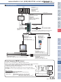
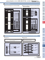
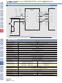
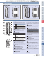
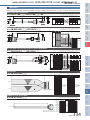
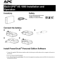
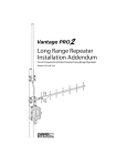
Controller Integrated Type
Controller
Splash
Proof Type
Cleanroom
Type
Gripper /
Rotary Type
Arm / Flat
Type
Rod
Type
Slider
Type
www.actuator.ru тел.:(495) 662-87-56, e-mail: iai@actuator.ru
SCON
Controller
Position controller
for RCS2 series
Type List
Position controller capable of operating RCP2 series actuator. Various control functions are combined into a single
unit.
C
Type
Name
Positioner mode
Solenoid valve mode
Pulse-train control mode Network specification (DeviceNet) Network specification (CC-Link)
External
view
Positioner supporting up Same control actions as Controller for pulse-train
control
to 512 positioning points those used on air cylinders
Number of
position points
Type of I/O
512 points
7 points
DeviceNet connection
specification (optional)
CC-Link connection
specification (optional)
512 points
512 points
DV
CC
(–)
NP/PN
Model
PS-24
Gateway
unit
Controller
Models
Description
C
Series
Type
PCON
ERC2
SCON
C
Encoder type
I/O type
I/O cable length Power-supply voltage
Standard type
ACON
20
I
Incremental
30R 30-W motor (RS)
A
Absolute
0
No cable
2
2m
100 100-W motor
3
3m
150 150-W motor
5
5m
ASEL
PSEL
SCON
60
60-W motor
200 200-W motor
NP
PIO NPN specification
300 300-W motor
PN
PIO PNP specification
400 400-W motor
DV
600 600-W motor
CC
SSEL
325
SCON
1
Single-phase 100VAC
2
Single-phase 200VAC
20-W motor
30D 30-W motor (RCS2)
750 750-W motor
XSEL
Motor type
(standard)
DeviceNet connection
specification
CC-Link connection
specification
* When selecting DV or CC as the I/O type,
please select 0 for the cable length.
SCON
Controller
System Configuration
Slider
Type
PLC
Controller Integrated Type
www.actuator.ru тел.:(495) 662-87-56, e-mail: iai@actuator.ru
Rod
Type
I/O cable for
pulse-train control type
CB-PACPU-PIO020
Cable length
Standard 2m
(Supplied with the controller)
Field network
Arm / Flat
Type
I/O flat cable
<Model CB-PAC-PIO020>
Cable length
Standard 2m
(Supplied with the controller)
Refer to p. 334 for details on a
replacement cable.
Gripper /
Rotary Type
* If command pulse
trains are of open
collector specification,
always use the pulse
converter AK-04
(optional).
Cleanroom
Type
Main
power Single-phase 100VAC
Single-phase 200VAC
* Always use a noise filter when supply
connecting a power supply.
Recommended model: MC1210 (Manufacturer: Densei-Lambda)
(You can purchase this through IAI. Contact us for details.)
PC software
(Refer to p. 333)
RS232 version
<Model: RCM-101-MW>
USB version
<Model: RCM-101-USB>
Controller
Models
Teaching pendant
(Refer to p. 333)
<Model: RCM-T / TD>
<Model: RCM-E>
<Model: RCM-P>
Controller
Pulse-train control cable
<Model CB-SC-PIOS >
(optional)
* Models of the network specification
(optional) can be connected directly
to a network.
Splash
Proof Type
Plug + shell for
pulse-train control
(Supplied with the
controller)
* The PC software comes with a cable.
Gateway
unit
PS-24
ERC2
Motor cable
<Model CB-RCC-MA>
Standard 1m / 3m / 5m
Refer to p. 334 for a replacement cable.
PCON
ACON
Encoder cable
<Model CB-RCS2-PA>
Standard 1m / 3m / 5m
Refer to p. 334 for a replacement cable.
Actuator RCP2 series
RCS2 series / Single-axis robot / Linear servo actuator
SCON
Pulse Converter AK-04 (Optional)
Content: Pulse converter (AK-04) + e-CON input/output connector
18
10
)
SSEL
(
ASEL
Basic specifications
• Input power supply: DC24V±10% (Max 50mA)
• Input pulses:
Open collector (collector current 12mA max.)
• Input frequency: 200kHz max.
• Output pulses:
26C31-equivalent differential output (Max 10mA)
Applicable wire:AWG 24~26, 0.14~0.3 mm2 (max.)
Outer diameter of finished wire ø1.0~1.2mm
PSEL
Use this converter if pulses output from the host controller are of open collector specification.
This converter is used to convert the open-collector command pulses output
from the host controller to differential pulses. Converting open collector pulses
to differential pulses improves noise resistance.
Two phases of differential pulses equivalent to those from the line driver 26C31
are output.
The e-CON connector is used as an input/output connector to simplify the field wiring.
50
326
XSEL
SCON
Controller Integrated Type
Slider
Type
Rod
Type
www.actuator.ru тел.:(495) 662-87-56, e-mail: iai@actuator.ru
SCON
Controller
I/O Specifications
n Input Part External input specifications
Item
Input voltage
Input current
Insulation method
Item
Load voltage
Maximum load current
Residual voltage
Insulation method
Specification
DC24V
100mA/point 400mA/8 points
Max 0.1mA/point
Photocoupler
Photocoupler
NPN specification
NPN specification
+24V
Cleanroom
Type
Gripper /
Rotary Type
Arm / Flat
Type
ON/OFF voltage
n Output Part External output specifications
Specification
24VDC ± 10%
4mA/point
ON voltage ... Min DC18.0V (3.5mA)
OFF voltage ... Max DC6.0V (1mA)
Each input
Load
5.6kΩ
Splash
Proof Type
Each input
10Ω
Logic
circuit
Internal
circuit
Internal
circuit
Logic
circuit
Each output
Load
Each output
Controller
0V
PNP specification
PNP specification
+24V
Controller
Models
Each input
Each input
5.6kΩ
Logic
circuit
Internal
circuit
Internal
circuit
Logic
circuit
10Ω
Load
Each output
Load
Each
output
I/O Specifications
The SCON-C supports all of the control methods shown below.
It supports a maximum of 512 positioning points in the positioner mode and up to seven points in the solenoid valve
mode.
n Controller Functions by Type
SCON-C
Features
Teaching mode
In this mode, the slider (rod) can be moved
by means of an external signal to store the
achieved position as position data.
Solenoid valve
mode
The actuator can be moved simply by ON/OFF of position
signals. This mode supports the same control actions you
are already familiar with on solenoid valves of air cylinders.
Pulse train
mode
In this mode, you can operate the actuator
freely using pulse trains without inputting
position data.
Network support
The controller can be connected directly to
a field network by selecting an applicable
network option.
XSEL
SSEL
ASEL
Positioner mode
A ba s i c o p e rati o n m o de in whi c h th e
actuator is operated by specifying a position
number and then inputting a start signal.
SCON
Type
PSEL
ACON
PCON
ERC2
PS-24
Gateway
unit
0V
327
SCON
SCON
Controller
Explanation of I/O Signal Functions
Rod
Type
n Controller Functions by Type
Abbreviation
CSTR
This signal is used to input a target position number (binary input).
Brake forced-release signal
This signal forcibly releases the brake.
RMOD
Running mode switching signal
This signal can switch the running mode when the MODE switch on the controller is
set to AUTO (AUTO when this signal is OFF, or MANU when the signal is ON).
* STP
Pause signal
Turning this signal OFF causes the moving actuator to decelerate to a stop. The actuator
will resume the remaining movement if the signal is turned OFF during the pause.
RES
Reset signal
Turning this signal ON resets the alarms that are present. If this signal is turned ON
while the actuator is paused (*STP is OFF), the remaining movement can be cancelled.
SON
Teaching mode signal
Turning this signal ON switches the controller to the teaching mode (provided that
CSTR, JOG+ and JOG- are all OFF and the actuator is not moving).
Jog/inching switching signal
The actuator can be jogged with JOG+ and JOG- while this signal is OFF. The
actuator performs inching operation with JOG+ and JOG- while this signal is ON.
------
----
Teaching signal
In the teaching mode, specify a desired position number and then turn this signal ON
for at least 20 ms to write the current position under the specified position number.
Start position command
Turning this signal ON in the solenoid valve mode causes the actuator to move to the
specified position. (Start signal is not required.)
Torque limit selection signal
While this signal is ON, torque is limited by the value set by a parameter. The TLR
signal turns ON if torque has reached the specified value.
Deviation counter clear signal
The position deviation counter is continuously cleared while this signal is ON.
Position complete signal
This signal turns ON when the actuator has entered the positioning band after
movement. If the actuator has exceeded the positioning band, PEND does not turn
OFF, but INP does. PEND and INP can be swapped using a parameter.
Completed position number signal
This signal is used to output the position number achieved at completion of
positioning (binary output).
HEND
Home return complete signal
This signal turns ON upon completion of home return.
ZONE1
Zone signal
This signal turns ON when the current actuator position has entered the range
specified by parameters.
PZONE
Position zone signal
This signal turns ON when the current actuator position has entered the range
specified by position data during position movement. PZONE can be used together
with ZONE1, but PZONE is valid only during movement to a specified position.
RMDS
Running mode status signal
This signal is used to output the running mode status.
* ALM
Controller alarm status signal
This signal remains ON while the controller is normal, and turns OFF if an alarm has
generated.
MOVE
Moving signal
This signal remains ON while the actuator is moving (including the periods during
home return and push-motion operation).
JISL
JOG+ JOG–
PWRT
ST0~ST6
TL
DCLR
PEND/INP
PM1~PM256
Mode status signal
This signal turns ON when the controller has switched to the teaching mode via
MODE signal input. It turns OFF upon returning to the normal mode.
Write complete signal
This signal remains OFF after the controller has switched to the teaching mode. It
turns ON upon completion of data write using the PWRT signal. If the PWRT signal is
turned OFF, this signal also turns OFF.
Current position number signal
This signal turns ON after the controller has completed moving to the target position
in the solenoid valve mode.
Torque limiting signal
This signal turns ON once the motor torque has reached the specified value in a
condition where torque is being limited by the TL signal.
Limit switch output signal
Each signal turns ON when the current actuator position has entered the positioning band
before or after the target position. If the actuator has already completed home return, these
signals are output even before a movement command is issued or while the servo is OFF.
---
--------
WEND
PE0~PE6
TLR
LSO~LS2
TRQS
328
XSEL
SCON
SSEL
MODES
ASEL
Emergency stop status signal
PSEL
* EMGS
SCON
This signal remains ON while the servo is on.
This signal remains ON while the controller is not in the emergency stop mode, and
turns OFF once an emergency stop has been actuated.
ACON
Servo ON status signal
PCON
SV
ERC2
Output
PS-24
MODE
Gateway
unit
Turning this signal ON performs home-return operation.
Controller
Models
The servo remains on while this signal is ON, or off while the signal is OFF.
Home return signal
Controller
Servo ON signal
HOME
Splash
Proof Type
Command position number signal
BKRL
Cleanroom
Type
Input
PTP strobe signal (start signal)
Input this signal to cause the actuator to start moving to the position set by the
command position number signal.
Gripper /
Rotary Type
PC1~PC256
Function description
Signal name
Arm / Flat
Type
Category
Slider
Type
The table below explains the functions assigned to the respective I/O signals of the controller.
Since the signals that can be used vary depending on the controller type and settings, check the signal table for each
controller to confirm the available functions.
Controller Integrated Type
www.actuator.ru тел.:(495) 662-87-56, e-mail: iai@actuator.ru
I/O Signal Table
Pin
Category
number
Parameter (PIO pattern) selection
5
1
0
4
2
3
Positioning mode Teaching mode 256-point mode 512-point mode Solenoid valve mode 1 Solenoid valve mode 2
Number of
positioning points
1A
2A
3A
4A
5A
6A
7A
8A
9A
10A
11A
12A
13A
14A
15A
16A
17A
18A
19A
20A
1B
2B
3B
4B
5B
6B
7B
8B
9B
10B
11B
12B
13B
14B
15B
16B
17B
18B
19B
20B
64 points
256 points
512 points
x
x
x
x
7 points
3 points
Pulse train mode
0
Pulse train mode
–
x
x
24V
P24
P24
24V
P24
−
NC
P24
NC
NC
−
NC
PC1
PC1
PC1
PC1
ST0
ST0
IN1
PC2
PC2
PC2
PC2
ST1
ST1 (JOG+)
RES
IN2
PC4
PC4
PC4
PC4
ST2
ST2 (–)
HOME
PC8
PC8
PC8
PC8
ST3
−
TL
IN4
PC16
PC16
PC16
PC16
ST4
−
CSTP
IN5
PC32
PC32
PC32
PC32
ST5
−
DCLR
IN6
−
MODE
PC64
PC64
ST6
−
BKRL
IN7
−
JISL
PC128
PC128
−
−
RMOD
IN8
−
JOG+
−
PC256
−
−
−
IN9
BKRL
JOG-
BKRL
BKRL
BKRL
BKRL
–
IN10
RMOD
RMOD
RMOD
RMOD
RMOD
RMOD
–
IN11
HOME
* STP
HOME
* STP
HOME
* STP
HOME
* STP
−
−
IN12
HOME
* STP
−
−
IN13
CSTR
CSTR/PWRT
CSTR
CSTR
−
−
−
IN14
RES
RES
RES
RES
RES
RES
–
IN15
SON
SON
SON
SON
SON
SON
–
OUT0
PM1
PM1
PM1
PM1
PE0
LSO
PWR
OUT1
PM2
PM2
PM2
PM2
PE1
LS1 (TRQS)
SV
OUT2
PM4
PM4
PM4
PM4
PE2
LS2(–)
INP
HEND
Input
Output
SON
IN0
IN3
OUT3
PM8
PM8
PM8
PM8
PE3
−
OUT4
PM16
PM16
PM16
PM16
PE4
−
TLR
OUT5
PM32
PM32
PM32
PM32
PE5
−
* ALM
OUT6
MOVE
MOVE
PM64
PM64
PE6
−
* EMGS
OUT7
ZONE1
MODES
PM128
PM128
ZONE1
ZONE1
RMDS
OUT8
PZONE
PZONE
PZONE
PM256
PZONE
PZONE
ALM1
OUT9
RMDS
RMDS
RMDS
RMDS
RMDS
RMDS
ALM2
OUT10
HEND
HEND
HEND
HEND
HEND
HEND
ALM4
OUT11
PEND
PEND/WEND
PEND
PEND
PEND
−
ALM8
OUT12
SV
* EMGS
SV
* EMGS
SV
* EMGS
SV
* EMGS
SV
–
OUT13
SV
* EMGS
* EMGS
–
OUT14
* ALM
* ALM
* ALM
* ALM
* ALM
* ALM
–
OUT15
* BLM
* BLM
* BLM
* BLM
* BLM
* BLM
−
–
–
–
–
0V
N
N
0V
N
N
SCON
PSEL
ASEL
SSEL
XSEL
64 points
Zone signal
P zone signal
ACON
PCON
ERC2
PS-24
Gateway
unit
Controller
Models
Controller
Splash
Proof Type
Cleanroom
Type
Gripper /
Rotary Type
Arm / Flat
Type
Rod
Type
Slider
Type
Controller Integrated Type
www.actuator.ru тел.:(495) 662-87-56, e-mail: iai@actuator.ru
SCON
Controller
329
SCON
SCON
Controller
Wiring Diagram
n Connection Diagram for Pulse-Train Control Mode
(Differential Output)
Twisted pair
Shield
Pin number Category Signal name
Not used
Not used
PP
/PP
NP
/NP
AFB
/AFB
BFB
/BFB
ZFB
/ZFB
GND
GND
Input
Output
Ground
Shell
Shield
Cleanroom
Type
1
2
3
4
5
6
7
8
9
10
11
12
13
14
Gripper /
Rotary Type
Shield
PIO connector (NPN)
Pin number Category Signal name
Power
supply
Input
—
Output
SON
RES
HOME
TL
CSTP
DCLR
BKRL
RMOD
Not used
PWR
SV
INP
HEND
TLR
*ALM
*EMGS
RMDS
ALM1
ALM2
ALM4
ALM8
Controller
Models
—
Not used
0V
0V
DC24V±10%
* The shield of the twisted pair cable connected to the PULSE connector must
be connected to the shell. Keep the cable length to 10 m or less.
* Connect 24V between pins 1A and 2A, and 0V between pins 19B and 20B.
Gateway
unit
Power
supply
24V
24V
Not used
Not used
Controller
1A
2A
3A
4A
5A
6A
7A
8A
9A
10A
11A
12A
13A~20A
1B
2B
3B
4B
5B
6B
7B
8B
9B
10B
11B
12B
13B~18B
19B
20B
Splash
Proof Type
1A
24V
Power
supply
2A
24V
Not used
—
3A
Not used
—
4A
IN0
5A
IN1
6A
IN2
7A
IN3
8A
IN4
9A
IN5
10A
IN6
11A
IN7
12A
Input
IN8
13A
IN9
14A
IN10
15A
IN11
16A
IN12
17A
IN13
18A
IN14
19A
IN15
20A
OUT0
1B
OUT1
2B
OUT2
3B
OUT3
4B
OUT4
5B
OUT5
6B
OUT6
7B
OUT7
8B
Output
OUT8
9B
OUT9
10B
OUT10
11B
OUT11
12B
OUT12
13B
OUT13
14B
OUT14
15B
OUT15
16B
Not used
—
17B
Not used
—
18B
DC24V±10%
0V
19B
Power
supply
0V
20B
* Connect 24V between pins 1A and 2A, and 0V between pins 19B and 20B.
Arm / Flat
Type
Pin number Category Signal name
Rod
Type
PULSE connector (NPN)
PIO connector (NPN)
Slider
Type
n Connection Diagram for Positioner Mode
Controller Integrated Type
www.actuator.ru тел.:(495) 662-87-56, e-mail: iai@actuator.ru
PS-24
Input/Output Specifications of Pulse-Train Control Type (Differential Line Driver Specifications)
n Output Part
26C32
or equivalent
ACON
SCON
Output method:
Line driver output
Insulated/not insulated:Not insulated
PCON
Maximum input pulses: Line driver interface 500kpps
Open collector interface 200kpps (AK-04 is needed)
Insulation method:
Photocoupler insulation
SCON
7.AFB
Internal
circuit
8./AFB
3.PP
4./PP
180Ω
9.BFB
Internal
circuit
11.ZFB
180Ω
Internal
circuit
ASEL
6./NP
Internal
circuit
12./ZFB
5.NP
13.GND
GND
14.GND
PSEL
Internal
circuit
10./BFB
SCON
26C31
or equivalent
ERC2
n Input Part
GND
SSEL
330
XSEL
SCON
Input/Output Specifications of Pulse-Train Control Type (Open Collector Specifications)
Slider
Type
Controller Integrated Type
www.actuator.ru тел.:(495) 662-87-56, e-mail: iai@actuator.ru
SCON
Controller
SCON
P24
(+DC24V)
Pulse converter
AK-04
Arm / Flat
Type
Rod
Type
N24
(0V)
1 24V
PP 1
3
PP
2 GND
/PP 2
4
/PP
3 PP
NP 3
5
NP
4 NP
/NP 4
6
/NP
Controller
Splash
Proof Type
Cleanroom
Type
Gripper /
Rotary Type
Host controller
N24 (0V)
ACON
PCON
ERC2
PS-24
Gateway
unit
Controller
Models
* Use the PIO interface power supply as the 24-VDC power supply to be connected to the AK-04.
* Minimize the cable length between the pulse output unit (PLC) and AK-04. Also keep the cable length between the AK-04 and PULSE connector to 2 m or less.
Specification Table
Item
Motor capacity
Connectable actuators
Number of controlled axes
Operation method
Number of positioning points
Backup memory
I/O connector
Number of I/O points
I/O power supply
Serial communication
Peripheral communication cable
Command pulse-train input method
Maximum input pulse frequency
Position detection method
Emergency stop function
Forced release of electromagnetic brake
Motor cable
Encoder cable
Specification
Less than 400W
400W or more
RCS2 series actuator / Single-axis robot / Linear servo actuator
1 axis
Positioner type / Pulse-train control type
512 points
EEPROM
40-pin connector
16 input points / 16 output points
Externally supplied 24VDC ± 10%
RS485 1ch
CB-PAC-PIO ccc
Differential line driver method / Open collector method (Conversion of open collector pulses to differential pulses using a pulse converter (Note 1))
Differentia line driver method: 500kpps max. / Open collector method (with a pulse converter): 200kpps max.
Incremental encoder / Absolute encoder
Available (built-in relay)
Brake release switch ON/OFF
CB-RCC-MA ccc (20m max.)
CB-RCS2-PA ccc (20m max.)
Single-phase 100~115VAC±10%
Single-phase 200~230VAC±10%
Single-phase 200~230VAC±10%
SSEL
ASEL
PSEL
SCON
Input power supply
20W / 74VA 30W / 94VA
60W / 186VA
100W / 282VA
150W / 376VA
200W / 469VA
Power-supply capacity
Dielectric strength voltage
Vibration resistance
Ambient operating temperature
Ambient operating humidity
Operating ambience
Protection class
Weight
External dimensions
XYZ directions
400W / 844VA
600W / 1212VA
750W / 1569VA
DC500V 100MΩ or more
10~57Hz One-side amplitude 0.035mm (continuous), 0.075mm (intermittent)
58~150Hz 4.9m/s2 (continuous), 9.8m/s2 (intermittent)
0~40˚C
10~95% (non-condensing)
Free from corrosive gases
IP20
Approx. 800g (+25g for absolute specification)
58mm(W) )×194mm(H) ×121mm(D)
Approx. 1.1kg
72mm(W) )×194mm(H) ×121mm(D)
XSEL
(Note 1) For the command-pulse input method, use the differential line driver method offering higher noise resistance. If the open collector method must be used, use an optional pulse converter (AK-04)
to convert open collector pulses to differential pulses.
331
SCON
SCON
Controller
External Dimensions
29
58
Slider
Type
Less than 400W
400W or more
.2
121
43
72
121
.2
ø4
Rod
Type
ø4
Controller Integrated Type
www.actuator.ru тел.:(495) 662-87-56, e-mail: iai@actuator.ru
Cleanroom
Type
5
5
184
194
(200.5)
Gripper /
Rotary Type
184
194
(200.5)
Arm / Flat
Type
When the absolute-data backup battery is installed
When the absolute-data backup battery is installed
1
2
9
10
3
5
7
13
14
15
16
PWR
緑
This LED comes on when the system becomes ready (= the CPU
is functioning properly after the power has been turned on).
SV
緑
This LED comes on when the servo turns on.
ALM
橙
This LED remains lit while an alarm is present.
EMG
赤
This LED remains lit while an emergency stop is actuated.
2 Rotary switch
T his switch sets an address to identify each
controller when multiple controllers are linked.
3 Piano switches
Controller system switches.
Description
1
Operation mode selector switch
OFF: Positioner mode, ON: Pulse-train control mode
* The setting will become effective after the power is
reconnected.
5 Regenerative unit connector
A connector for the actuator’s motor cable.
7 Power-supply connector
An AC power-supply connector. Divided into the
control power input and motor power input.
A screw for protective grounding. Always connect
this screw to ground.
Accept PI commands.
12 SIO connector
A c o n n e c to r fo r a te a c h i n g - p e n d a n t o r P C
communication cable.
13 Brake release switch
A switch to forcibly release the electromagnetic brake
equipped on the actuator.
* A 24-VDC power supply for driving the brake must be connected.
14 Brake power-supply connector
A connector for supplying 24-VDC brake power.
(Required only when an actuator with brake is
connected.)
15 E n c o d e r / s e n s o r c o n n e c t o r
(compatible with XSEL-P/Q)
A connector for the encoder/sensor cables.
connector for the absolute-data backup battery.
A
(Required only when an absolute-encoder actuator is
used.)
16 Absolute-data backup battery connector
17 Absolute-data backup battery holder
A battery holder into which the absolute-data backup
battery is set.
332
XSEL
SCON
SSEL
8 Grounding screw
AUTO
* The emergency stop switch on the teaching pendant becomes
effective when the line is connected, regardless of whether this
switch is set to AUTO or MANU. Take note that an emergency stop
will be actuated momentarily when the teaching-pendant or SIO
communication cable is disconnected. This is a normal phenomenon
and does not indicate an error.
ASEL
(compatible with XSEL, ECON and RCS)
Description
PSEL
6 Motor connector
Name
MANU Do not accept PI commands.
SCON
A connector for the resistor unit that absorbs
regenerative current produced when the actuator
decelerates to a stop.
11 Running mode selector switch
ACON
4 System I/O connector
A connector for the emergency stop switch, etc.
10 PIO connector
connector for a cable used to perform parallel
A
communication with a PLC and other peripherals.
PCON
Remote update switch (normally set to OFF)
OFF: Normal operation mode, ON: Update mode
* The setting will become effective after the power
is reconnected or following a software reset.
pulse-train control mode. It remains unconnected if
the controller is operated in the positioner mode.
ERC2
Name
2
17
Description
PS-24
8
12
Name Color
Gateway
unit
6
11
9 Dedicated pulse-train control connector
A connector used to operate the controller in the
Controller
Models
4
1 LED indicators
These LED indicate the condition of the controller.
Controller
Name of Each Part
Splash
Proof Type
4.2
4.2
Options
n Teaching Pendant
An input device that provides all functions you need for trial operation and adjustment, such as position data input,
test operation, as well as monitoring of current axis positions and input/output signals.
Name
Teaching Pendant
Simple teaching pendant
Data setting unit
Model
RCM-T (standard specification)
RCM-TD (with deadman switch *1)
RCM-E
RCM-P
Standard price
—
—
—
A standard, user-friendly teaching pendant
equipped with a large LCD screen.
A deadman switch type ensuring added safety
is also available.
An economical type offering the same
functions as the RCA-T at a substantially lower
price.
An affordable data setting unit that provides all
editing functions other than those relating to
axis operation.
Display
21 characters x 16 lines on LCD
16 characters x 2 lines on LCD
16 characters x 2 lines on LCD
Weight
Approx. 550g
Approx. 400g
Approx. 360g
Cable length
5m
5m
5m
External view
Ambient operating
temperature, humidity
Temperature: 0~40°C, Humidity: 85% RH or below
32.5
7.5
(113.5)
15.1 26.2
ACON
PCON
ERC2
PS-24
Gateway
unit
23
148.5
ø4.8
80
7
72.5
(34)
*1 The deadman switch is a safety switch that cuts off the drive source when released to disable operation.
n PC Software
A software program that helps input position data and perform test operation.
It significantly facilitates debugging operation by offering wide-ranging functions including jogging, inching, step
operation and continuous operation.
n RS232
Communication Type
Model RCM-101-MW
n USB
Communication Type
Model RCM-101-USB
<Content>PC software (CD-ROM),
PC cable
(communication cable +
RS232 conversion unit)
<Content>PC software (CD-ROM),
PC cable
(communication cable + USB
conversion unit + USB cable)
n Regenerative Resistance Unit
Features
This unit returns regenerative electric current when the motor builds heat as it decelerates.
Please verify the total W of the actuator from the chart at the right, as it is necessary to make
preparations to the regenerative resistance.
0.9kg
Weight
Built-in regenerative resistor 220 80W
Unit-controller
CB-SC-REU010 (SSEL)
connection cable (supplied)
* Please arrange one each of REU-2 and REU-1 (page 372), when two
regenerative units are necessary.
n Battery for Absolute Data Storage
Guide for Determining Necessary Number of Units
Horizontal
Vertical
0 unit
~200W
~100W
1 unit
~750W
~400W
~750W
2 units
* There may be times when more regenerative
resistance is needed than listed above
depending on operating conditions.
External Dimensions
ø5
34
175
SSEL
186
195
PSEL
Model
REU-2 (SCON/SSEL)
Specifications
ASEL
SCON
249.5
External
dimensions
86
6.3
140
Controller
Models
43
105
5
16.6
XSEL
* This unit does not support operations relating to axis movement.
21
Features
23.5
Controller Integrated Type
Slider
Type
Rod
Type
Arm / Flat
Type
Gripper /
Rotary Type
Cleanroom
Type
Splash
Proof Type
Controller
www.actuator.ru тел.:(495) 662-87-56, e-mail: iai@actuator.ru
SCON
Controller
333
SCON
126
Features This battery is for storing
absolute data for the
operating actuator.
Model
AB-5
www.actuator.ru тел.:(495) 662-87-56, e-mail: iai@actuator.ru
Controller
Controller Integrated Type
Should you require spare parts after the purchase of your product for replacing the original cables, etc., refer to the model names specified below.
Slider
Type
SCON
Spare Parts
Motor Cable / Motor Robot Cable
* c c c indicates the cable length (L). Lengths up to
30 m can be specified. Example) 080 = 8 m
CB-RCC-MA c c c /CB-RCC-MA c c c -RB
(20)
L
(10)
Wire
(ø9)
1
(Front view)
(18)
(41)
4
1
Color Signal
Green
Red
0.75sq
White
Black
4
(Front view)
Actuator end
PE
U
V
W
No.
No.
1
2
3
4
1
2
3
4
Signal Color
Wire
U
Red
V White 0.75sq
W Black (crimped)
PE Green
Encoder Cable / Encoder Robot Cable
Model
* c c c indicates the cable length (L). Lengths up to
30 m can be specified. Example) 080 = 8 m
CB-RCS2-PA c c c /CB-X2-PA c c c
Wire
(15)
26
13
(Front view)
1 10
(25)
1
Actuator end
9 18
(Front view)
10
11
12
13
26
25
24
23
9
18
19
1
2
3
4
5
6
7
8
14
15
16
17
20
21
22
Connect the shield to the hood via a clamp.
Note 3
Note 4
Note 1
No. Signal
A
A
B
B
Z
Z
LS+
–
FG
SD
SD
BAT+
BAT–
VCC
GND
LS–
BK–
BK+
1
2
3
4
5
6
7
8
9
10
11
12
13
14
15
16
17
18
Drain wire and braided shield wire Note 2
Color
Pink
Green
White
Blue / Red
Orange / White
Green / White
Brown / White
Drain
Blue
Orange
Black
Yellow
Green
Brown
Grey / White
Grey
Red
Wire
AWG26
(crimped)
Controller
Controller end
Signal No.
Splash
Proof Type
(37)
(13)
14
Color
–
–
E24V
0V
Grey / White
LS
Brown / White
CLEEP
OT
RSV
–
AWG26
–
–
(soldered)
A+
Pink
APurple
B+
White
BBlue / Red
Z+
Orange / White
ZGreen / White
SRD+
Blue
SRDOrange
BAT+
Black
BAT–
Yellow
VCC
Green
GND
Brown
BKRGrey
BKR+
Red
–
-
(14)
L
Cleanroom
Type
(41)
Gripper /
Rotary Type
Controller end
Arm / Flat
Type
(21)
(16)
Rod
Type
Model
Encoder Cable / Encoder Robot Cable for RCS2-RT6/RT6R/RT7
Model
* c c c indicates the cable length (L). Lengths up to
30 m can be specified. Example) 080 = 8 m
CB-RCS2-PLA c c c /CB-X2-PLA c c c
Wire
L
(41)
(14)
1
(18)
(13)
1 6 10
1
13
Actuator end
(Front view) Controller end
–
–
–
A+
A–
B+
B–
Z+
Z–
SRD+
SRD–
BAT+
BAT–
VCC
GND
BKR–
BKR+
–
AWG26 White / Yellow
(soldered) White / Red
White / Black
White / Purple
White / Grey
Orange
Green
Purple
Grey
Red
Black
Blue
Yellow
9 18
(15)
-
No.
10
11
12
13
26
25
24
23
9
18
19
1
2
3
4
5
6
7
8
14
15
16
17
20
21
22
Connect the shield to the hood via a clamp.
No.
No.
Drain wire and braided shield wire
(“White/blue” and other designations under “Wire color” indicate the band color/insulator color.)
Signal
Wire
Color
White / Blue
White / Yellow
White / Red AWG26
White / Black (crimped)
White / Purple
White / Grey
Signal
Wire
Color
White / Blue
White / Yellow
White / Red
White / Black AWG26
White / Purple (crimped)
White / Grey
Drain
Orange
Green
Purple
Grey
Red
Black
Blue
Yellow
E24V
0V
LS
CLEEP
OT
RSV
1
2
3
4
5
6
A
A
B
B
Z
Z
–
–
FG
SD
SD
BAT+
BAT–
VCC
GND
–
BK–
BK+
1
2
3
4
5
6
7
8
9
10
11
12
13
14
15
16
17
18
PS-24
-
–
–
Gateway
unit
26
Signal
White / Blue
(25)
(37)
14
Color
-
White / Orange
E24V
White / Green
0V
Brown / Blue
LS
Brown / Yellow CLEEP
Brown / Red
OT
Brown / Black
RSV
(8)
Controller
Models
LS end
I/O Flat Cable
CB-PAC-PIO c c c
* c c c indicates the cable length (L). Lengths up to
10 m can be specified. Example) 080 = 8 m
L
No connector
A
20B
1A
1B
Half-pitch MIL socket:
HIF6 – 40D – 1.27R (Hirose)
Model
CB-SC-PIOS c c c
* c c c indicates the cable length (L). Lengths up to
10 m can be specified. Example) 080 = 8 m
SCON
334
XSEL
Shield
Color Signal No.
Black Unused 1
White / Black Unused 2
3
PP
Red
4
White / Red /PP
5
NP
Green
6
White / Green /NP
0.2sq Yellow AFB 7
(soldered) White / Yellow /AFB 8
Brown BFB 9
White / Brown /BFB 10
ZFB 11
Blue
White / Blue /ZFB 12
GND 13
Grey
White / Grey GND 14
Connect the shield to a cable clamp.
SSEL
No connector
Wire
ASEL
L
Black
White / Black
Red
White / Red
Green
White / Green
Yellow
White / Yellow
Brown
White / Brown
Blue
White / Blue
Grey
Plug: 10114—300PE (Sumitomo 3M)
White / Grey
Shell: 10314—52F0—008 (Sumitomo 3M)
PSEL
SCON Pulse-Train Control Cable
SCON
Flat cable (20 cores) x 2
20A
Cable
ACON
B
Signal
No. name
Wire
color
1B OUT0 Brown-3
2B OUT1 Red-3
3B OUT2 Orange-3
4B OUT3 Yellow-3
5B OUT4 Green-3
6B OUT5 Blue-3
7B OUT6 Purple-3
8B OUT7 Grey-3
9B OUT8 White-3
10B OUT9 Black-3
Flat cable B
11B OUT10 Brown-4 (pressure-welded)
AWG28
12B OUT11 Red-4
13B OUT12 Orange-4
14B OUT13 Yellow-4
15B OUT14 Green-4
16B OUT15 Blue-4
Purple-4
17B
—
Grey-4
18B
—
19B 0V White-4
Black-4
20B 0V
PCON
No connector
HIF6 – 40D – 1.27R
Signal Cable
No. name
Wire
color
1A 24V Brown-1
Red-1
2A 24V
— Orange-1
3A
Yellow-1
—
4A
IN0 Green-1
5A
Blue-1
IN1
6A
IN2 Purple-1
7A
Grey-1
IN3
8A
IN4 White-1
9A
10A IN5 Black-1
Flat cable A
11A IN6 Brown-2 (pressure-welded)
AWG28
Red-2
12A IN7
13A IN8 Orange-2
14A IN9 Yellow-2
15A IN10 Green-2
16A IN11 Blue-2
17A IN12 Purple-2
18A IN13 Grey-2
19A IN14 White-2
20A IN15 Black-2
ERC2
Model