1
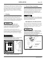
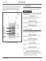
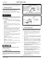
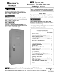
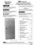
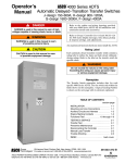
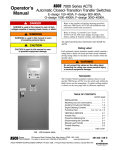
Operator’s
Manual
Series 185
Automatic Transfer Switches
100 through 400 ampere sizes
DANGER is used in this manual to warn of a
hazard situation which, if not avoided, will result in
death or serious injury.
WARNING is used in this manual to warn of a
hazardous situation which, if not avoided, could
result in death or serious injury.
CAUTION is used in this manual to warn of a
hazardous situation which, if not avoided, could
result in minor or moderate injury.
An experienced licensed electrician must install the ATS.
Refer to the outline and wiring drawings provided with
your ASCO Series 185 ATS for all installation details.
ASCO Series 185 Automatic Transfer Switches (ATSs) are
Listed under Underwriter’s Laboratories Standard for
Transfer Switch Equipment, UL–1008. They are intended
for use only in optional standby systems in accordance with
the National Electrical Code, NEC/NFPA 70, Article 702.
This ATS is for use with 2–wire automatic–start generators
only.
Refer to Application Information 381339–292 to confirm
that you have selected the appropriate product for the
intended installation.
This automatic transfer switch is intended for standby
power applications in residential / light commercial use
only.
This product is not intended for emergency
or life–support systems.
If you have more stringent application requirements contact
ASCO Power Technologies for other products suitable for
critical applications.
Rating Label
Each automatic transfer switch contains a rating label to
define the loads and fault circuit withstand / closing ratings.
Refer to the label on the transfer switch for specific values.
Do not exceed the values on the rating label.
Exceeding the rating can cause person injury or
serious equipment damage.
TABLE OF CONTENTS
page
INSTALLATION . . . . . . . . . . . . . . . . . . . . . . . . . . 1
CONTROLLER . . . . . . . . . . . . . . . . . . . . . . . . 2–5
FUNCTIONAL TEST . . . . . . . . . . . . . . . . . . . . . . 6
SEQUENCE OF OPERATION . . . . . . . . . . . . . 7
TROUBLESHOOTING . . . . . . . . . . . . . . . . . . 8–9
100–230 ampere sizes
INDEX . . . . . . . . . . . . . . . . . . . . . . . . . . . . . . . . . 10
50 Hanover Road, Florham Park, New Jersey 07932–1591 USA
For sales or service call 1 800 800–2726 (ASCO) www.ascopower.com
381333–319 E
ASCO POWER TECHNOLOGIES CANADA PO Box 1238, 17 Airport Road, Brantford, Ontario, Canada N3T 5T3
Series 185
Catalog Number Identification
Nameplate
The Transfer Switch nameplate includes data for
each specific ASCO Series 185 ATS. Use the ATS
only within the limits shown on this nameplate.
D 185
Neutral
A – standard
A
Phase Poles
2 – single Ø
clock battery
2
A typical Catalog Number is shown below with its
elements explained. The example is for a D–design,
2 pole, 200 A, 220–240 V, in Type 1 indoor enclosure:
200
F
Amperes
100
200
230
260
400
4
Voltage
F 220--- 240
C
Controller
Enclosure
4 – standard
C – Type 1
M – Type 3R
4X – if
accessories
ordered
load power
connections
cable spacers
(see INSTALLATION)
emergency
power
connections
neutral
connections
terminals
for optional
switch
position
contacts
(shown
installed)
Transfer
Switch
ground
connections
membrane
controls
generator
control
connections
Controller
harness plug
utility power
connections
200 ampere size in typical enclosure with location of customer connections
381333–319 E
INSTALLATION
Installation of the ASCO Series 185 automatic transfer
switch (ATS) must be performed by a licensed electrician.
It must be installed according to the National Electrical
Code (NEC) and all local electrical code requirements.
Remove the enclosure cover and inspect the ATS for
shipping damage. If damage is evident do not install the
ATS.
1 --- Mounting
Refer to the enclosure outline drawing. Mount the ATS
according to details and instructions shown on this
diagram. Mount the ATS vertically to a rigid supporting
structure. Level all mounting points by using flat washers
behind the holes to avoid distortion of the enclosure.
Series 185
2 --- Electrical Power Connections
Refer to the wiring diagram. The ATS must be protected
by suitably sized circuit breakers feeding the utility and
generator source terminals. The rating of the circuit
breakers must be based on the requirements of the
National Electrical Code for its nameplate ampere and
short circuit withstand ratings.
ELECTROCUTION HAZARD Turn off utility power
and turn off the generator to prevent electrocution
when wiring the transfer switch.
Cable Spacers for 150, 200, and 230 A
NOTICE
Three cable spacers are included with 150, 200, and 230
ampere transfer switches. Run the copper power cables
through the cable spacers as shown in Figure 2. Position
the cable spacers approximately 1½ inches from the
terminal lugs.
MALFUNCTION or SHORTENED LIFE
Protect the automatic transfer switch from
construction grit and metal chips to prevent
malfunction or shortened life of the ATS.
NOTICE
Transfer switches rated 260 and 400 amperes are
mounted on an insulator backing piece (installed behind
the transfer switch). If the transfer switch is removed
from the enclosure and then reinstalled, this insulator
must be placed behind the transfer switch. See Figure 1.
CABLE LOOSENING DUE TO SHORT CIRCUIT
Install three cable spacers 1 1/2 inches from the
power terminals to prevent the cables from
loosening during a short–circuit condition on 150,
200, and 230 ampere transfer switches.
cable spacers
FLASH HAZARD – DAMAGE
Be sure that the insulator piece is installed behind
the 260 and 400 ampere transfer switches.
insulator
backing
piece
1 ½ inch approximate
use copper power
cables only for
200 and 230 A
cable spacer
Figure 2. Cable spacers for 150, 200, and 230 A.
Figure 1. Insulator for 260 and 400 A.
1
381333–319 E
CONTROLLER
Series 185
1 --- Push Buttons
The Group 4 digital Controller is used in ASCO Series
185 automatic transfer switches. It provides the sensing,
timing, and control functions for the ATS. This micro–
processor–based controller includes built–in control
buttons and status lights for control of the ATS and
generator.
On the front control display are three push buttons that
control the operation of the generator and the ATS.
Before using the transfer test button, be sure that
conditions are safe for running the generator and
for load transfer.
clock
battery
cover
see page 3
Transfer Test
Use this button to test the system. This operation starts
the generator and transfers the load. Be sure that
conditions are safe to do this operation.
Bypass Time Delay
Use this button to cancel the active time delay or exercise
period (stops the generator after cooldown).
Utility
Acceptable
light
Transfer
Test
button
Set Engine Exerciser
Use this button to set the automatic generator exerciser
(page 3).
Load on
Utility light
2 --- Indicator Lights
Bypass
Time Delay
button
On the front control display are five lights that indicate
the status of the sources and the ATS.
Set Engine
Exerciser
button
Load on
Generator
light
Automatic
Generator
Exerciser
light
Utility Acceptable
This light indicates that the utility voltage is acceptable
for connection to the load.
Generator
Acceptable
light
Generator Acceptable
This light indicates that the generator voltage is
acceptable for connection to the load.
Figure 3. Front view of controller.
Load on Utility
This light indicates that the load is connected to the
utility.
Load on Generator
This light indicates that the load is connected to the
generator.
Automatic Generator Exerciser
This light indicates the status of the generator exerciser:
--- blinks during the exercise period (including cooldown).
--- stays on when the exerciser has been set.
--- is off when the exerciser has not been set.
381333–319 E
2
CONTROLLER (continued)
Series 185
3 --- Generator Starting Contacts
5 --- Automatic Generator Exerciser
The generator starting contacts connections are on the
controller. Refer to the generator manual. Disconnect
the generator battery and verify that the ignition switch is
in the OFF position. Connect the generator starting
wires to the appropriate terminals on terminal block TB7
as shown on the wiring diagram. For wiring convenience
terminal block TB7 has a removable plug. See Figure 4
and Table A.
The built–in automatic generator exerciser can be set to
exercise the generator for 20 minutes once every week.
Clock Battery
Be sure a fresh battery is installed and turned on. It will
maintain the exerciser clock for about 24 hours in case of
a power outage.
Recommended 9 volt alkaline batteries are (see Figure
5): Duracell MN 1404, Everready 522, Panasonic 6AM6
Turn on battery by putting S2 DIP switch actuator 10 in
the on position (up). See Table B and Figure 6.
1 2 3 4 5 6 7 8 9
Exercise with or without Load
TB7
removable
terminal block
Figure 4. TB7 generator starting contact terminals.
The generator should be exercised under load or follow
the recommendations of the generator manufacturer. Be
sure the exerciser is turned on. Then select either
exercise with or without load. The ATS will transfer the
load to the generator when the exercise with load is
selected. See Figure 6 and Table B.
Table A. Generator Start Connections
Table B. Generator Exercise Settings
TB7–4, TB7–5, TB7–6
When the Utility fails
Terminals on Controller
Function
Factory
Setting
DIP
Switch
DIP
Actuator
contact closes
TB7–4 and TB7–5
contact opens
TB7–5 and TB7–6
clock
battery
off
S2
10
exerciser
off
S1
7
with load or
without load
without
load
S1
8
4 --- Settings
The time delay and sensor setting in the Group 4
controller are accessible on the inside. Refer to Tables B
and C and to Figures 6 and 7. Use a ball–point pen or
other pointed tool to slide the DIP switch actuators up or
down to match setting shown.
Actuator
Position
on (up)
off (down)
on (up)
off (down)
with (up)
without (down)
To Set Exerciser
Press and hold (5 seconds) the Set Engine Exerciser
button. The exercise period occurs immediately and at
approximately the same time weekly thereafter. The
status light below the button blinks during the exercise
period (including the cooldown). The light stays on to
indicate that the exerciser has been set. If the light is off,
the exerciser has not been set.
All power must be off before making any changes.
The factory default settings are shown in Table G on
page 5.
To Cancel an Active Exercise Period
cover must be removed
to replace 9V battery
(use alkaline type)
Press the Bypass Time Delay button to stop an exercising
generator. If exercise with load is set, the ATS
retransfers the load to the utility, then stops the
generator after cooldown.
screw
Figure 5. Battery replacement.
3
381333–319 E
CONTROLLER (continued)
Series 185
S1 DIP switch
S3 DIP switch
S2 DIP switch
Figure 6. DIP switches S1 and S2 at the top right.
The time delay settings are shown in Figures 6 and 7 and
in Table C. The sensor settings are shown in Figure 6
and in Table D. The standard (factory) settings are
shown in Tables C, D, and H.
Figure 7. DIP switch S3 at the bottom center.
Table C. Time Delay Settings
Time Delay Description
Factory Setting
override momentary
utility outages
3 seconds
transfer to generator
10 seconds (approx.)
override momentary
generator outages
4 seconds
transfer to utility
5 minutes (approx.)
unloaded running
(generator cooldown)
2 minutes
load disconnect delay
before transfer (and delay
after transfer, if enabled)
0 seconds
Settings
DIP Switch
DIP Actuator
Actuator Position
1 second
S2
1
on (up)
3 seconds
S2
1
off (down)
–
–
–
–
4 second
S3
9
on (up)
0
S3
9
off (down)
–
–
–
–
2 minutes
S1
10
on (up)
5 minutes
S1
10
off (down)
0 seconds
S3
7, 8
both on (up)
3 seconds
S3
7, 8
7 on (up), 8 off (down)
10 seconds
S3
7, 8
7 off (down), 8 on (up)
20 seconds
S3
7, 8
both off (down)
Table D. Voltage and Frequency Settings
Setting Description
voltage
frequency
phase
Setting
Factory Setting
Settings
DIP Switch
DIP Actuator
Actuator Position
–
220 – 240 V
non–adjustable
S2
2
on (up)
nominal
60 Hz
50 Hz
S1
4
on (up)
–
single
pickup
198 V
60 Hz
S1
4
off (down)
non–adjustable
S1
6
on (up)
198 V
S1
3
on (up)
209 V *
S1
3
off (down)
S1
1
off (down)
S1
2
off (down)
S1
1
on (up)
S1
2
off (down)
S1
1
off (down)
S1
2
on (up)
S1
1
on (up)
S1
2
on (up)
non adjustable
non–adjustable
–
–
–
non adjustable
non–adjustable
–
–
–
198 V *
utility voltage
187 V
dropout
187 V
176 V
154 V
generator voltage
generator frequency
pickup
198 V
dropout
165 V
pickup
57 Hz (nom 60 Hz)
48 Hz (nom 50 Hz)
dropout
51 Hz (nom 60 Hz)
43 Hz (nom 50 Hz)
* If the dropout voltage is set to 198 V, the pickup voltage must be set to 209 V.
381333–319 E
4
CONTROLLER (continued)
7 --- Factory Settings --- Summary
6 --- Remote Control & Load Disconnect
Table H. Factory Settings – Summary
These remote control features require a customer–
supplied normally–closed contact suitable for a 5 V dc
low energy circuit. Refer to the wiring diagram provided
with the ATS. Activate the appropriate DIP switch S3
actuators as shown in Tables E, F, or G. See Figure 7.
DIP Switch
DIP Actuator
Actuator Position
1
on (up)
2
off (down)
3
on (up)
4
off (down)
5
off (down)
6
on (up)
7
off (down)
8
off (down)
Remote test
Normally–closed input. When opened, it simulates a
utility failure. The generator is signalled to start
immediately and the load transfers to the generator (if
acceptable). If the generator fails, the load stays on the
generator until the remote test circuit is closed.
S1
Table E. Remote test
Function
Factory
Setting
DIP
Switch
DIP
Actuator
disabled
enabled
disabled
(on)
S3
3
Actuator
Position
on (up)
off (down)
Remote test (with automatic retransfer)
S2
Normally–closed input. When opened, it simulates a
utility failure. The generator is signalled to start
immediately and the load transfers to the generator (if
acceptable). If the generator fails, the load transfers
back to the utility (if acceptable).
Table F. Remote transfer to generator
Function
Factory
Setting
disabled
enabled
disabled
(on)
DIP
Switch
S3
DIP
Actuator
2
Actuator
Position
on (up)
off (down)
Bypass load transfer to utility time delay
S3
Normally–closed input. When opened, it bypasses or
cancels the generator to utility load transfer time delay.
The load transfers back to the utility.
Table G. Bypass load transfer to utility delay
Function
Factory
Setting
DIP
Switch
DIP
Actuator
disabled
enabled
disabled
(on)
S3
1
Series 185
Actuator
Position
on (up)
off (down)
9
off (down)
10
on (up)
1
off (down)
2
on (up)
3
off (down)
4
on (up)
5
on (up)
6
on (up)
7
on (up)
8
on (up)
9
off (down)
10
off (down)
1
on (up)
2
on (up)
3
on (up)
4
on (up)
5
on (up)
6
off (down)
7
on (up)
8
on (up)
9
on (up)
10
on (up)
Table I. Load disconnect delay before transfer
Load disconnect feature
Connect external circuits to the terminals indicated on
the wiring diagram. The double throw (Form C) contact
operates prior to a selectable 0, 3, 10, or 20 second delay
before transfer of the ATS. The contact resets either
immediately following transfer or after the same delay as
set for presignal before transfer. Time delay between the
load disconnect control signal and initiation of transfer is
set on the controller DIP switch S3 (actuators 6, 7, 8).
Function
Factory
Setting
DIP
Switch
0 seconds
disabled
S3
3 seconds
S3
10 seconds
S3
20 seconds
S3
DIP
Actuator
7
8
7
8
7
8
7
8
Actuator
Position
on (up)
on (up)
on (up)
off (down)
off (down)
on (up)
off (down)
off (down)
Table J. Load disconnect delay after transfer*
Function
* Enabling the delay after transfer will cause the control signal to reset
after the same delay as set for the delay before transfer.
disabled
enabled
5
Factory
Setting
disabled
DIP
Switch
S3
S3
DIP
Actuator
6
6
Actuator
Position
off (down)
on (up)
381333–319 E
Series 185
FUNCTIONAL TEST
After installing the Series 185 automatic transfer switch
(ATS) perform the following three–part functional test.
maintenance handle
With ALL POWER OFF
grasp maintenance
handle and turn it
quickly with your
thumb and fingers.
1 --- Manual Operation
A handle is provided on the transfer switch for
maintenance purposes only. Manual operation of the
transfer switch should be checked before it is energized
(operated electrically).
weight marked P (utility) and A (generator)
Figure 8. Maintenance handle for 100–230 A.
Do not manually operate the transfer switch until
both power sources are disconnected: open both
circuit breakers.
1.
Turn OFF both the utility and generator circuit
breakers feeding the ATS. Verify that ALL POWER
IS OFF!
2.
100–230 A
Grasp the maintenance handle and turn it quickly
with your thumb and fingers to manually operate the
transfer switch.
260–400 A
Insert the maintenance handle into the hole in the
shaft, left side of the operator. Move the handle as
shown to manually operate the transfer switch.
3.
4.
hole
shaft
Figure 9. Maintenance handle for 260–400 A.
3 --- Electrical Operation
This procedure checks the electrical operation of the ATS.
The switch should operate smoothly without binding.
If it does not, check for shipping damage or
construction debris.
After checking the manual operation, use the handle
again to return the transfer switch to the utility
source position.
100–230 A see Figure 8.
The letter P (utility) on the round weight is facing
you.
260–400 A see Figure 9.
The letter N (utility) on the round weight is facing
you.
Remove the maintenance handle and store it on the
transfer switch in the place provided.
NOTICE
260–400 A Remove the maintenance handle
before proceeding!
2 --- Voltage Checks
The ATS is rated for 220–240 V ac 60 or 50 Hz. Verify that
both the utility and generator sources are 220–240 V ac 60
or 50 Hz.
381333–319 E
maintenance
handle
1.
Install the enclosure cover and tighten the screws.
2.
Verify that the generator battery is connected and
that the generator’s starting controls are set for
automatic.
3.
Turn on both the utility and generator circuit breakers.
4.
Verify that the Utility Acceptable and Load on Utility
lights are on.
5.
This step will start the generator. Press and hold the
Transfer Test button until the Generator Acceptable
light comes on and stays on. Then release the button.
6.
After the Generator Acceptable light comes on, the
ATS transfers the load from the utility to the
generator (after approx. 10 second delay). The Load
on Generator light comes on.
7.
The ATS stays connected to the generator for
5 minutes (approx.). The utility must be acceptable
for 5 minutes continuously. Then the load is
transferred back to the utility. To bypass time delay,
press the Bypass Time Delay button.
8.
After load retransfer to utility, the generator runs
2 minutes (without load), then shuts down. The
Generator Acceptable light goes off indicating that
the generator is off.
This completes the Functional Test.
6
Sequence of Operation --- Utility Failure
Series 185
light is on
light is off
¡
generator
stops
Utility power good.
Electrical loads on utility
generator runs
unloaded
for 2 min.
utility acceptable
Utility fails
(longer than
3 sec.)
load on utility
¥
electrical loads
switched back
to utility
©
utility acceptable
generator off
load on utility
wait 5 min.
for utility
to stabilize
generator
acceptable
utility
acceptable
start
generator
utility off
observe
these
power
lights
observe
these
switch
lights
load off
generator off
generator
starting
utility off
load on utility
load on generator
utility off
generator acceptable
¤
utility
returns
load on generator
waiting for utility
to return
generator
acceptable
¢
generator
acceptable
wait 10 sec.
for generator
to warm up
generator acceptable
£
electrical loads
switched to generator
7
381333–319 E
TROUBLESHOOTING
Series 185
This troubleshooting guide describes some of the simple
causes of problems with the installation of the automatic
transfer switch. Troubleshooting beyond the scope of this
guide should not be attempted by the installer. A licensed
electrician must perform all internal troubleshooting.
ASCO Power Technologies can be contacted at:
1–800–800–2726 or customercare@asco.com
Problem
The Utility Acceptable light
1.
does not come on when utility 2.
power is connected to the ATS.
381333–319 E
With ALL POWER OFF, verify that the utility feed is 220–240 V ac and 60 Hz.
Check DIP switch S2 actuator 2, and DIP S1 actuator 4. See Table D for voltage
and frequency settings.
With ALL POWER OFF, verify that the utility feed is wired to the terminal lugs
on the bottom of the transfer switch marked L1 and L5. See the wiring diagram.
4.
With ALL POWER OFF, verify that the transfer switch harness is connected
properly to the controller (plug and receptacle tight).
Hold the Transfer Test button for at least 15 seconds.
Verify that the generator starting controls are set for automatic operation (not in
manual mode).
Verify that the generator battery is connected and that the battery voltage meets
the generator manufacturer’s recommendation.
4.
Verify that the correct contact (normally open or normally closed) is being
utilized (see the generator manual).
5.
With ALL POWER OFF, verify engine start low voltage wiring between the
controller terminal block and the generator. See the wiring diagram. Check that
the plug is properly seated in the receptacle on the controller.
Verify proper generator operation (fuel in tank, oil level, spark plugs --- see
generator manual).
The generator cranks but does 1.
not start and run when the utility source fails or when the
Transfer Test button is pressed. 2.
The generator starts and runs
but the ATS does not transfer
the load to the generator.
Cause and Solution
Verify that the utility feed is connected and that its circuit breaker is ON.
3.
The generator does not crank
1.
when the utility source fails or 2.
when the Transfer Test button is
pressed.
3.
The generator starts and runs
but the Generator Acceptable
light does not come on.
ELECTROCUTION FLASH HAZARD Do not work
on the transfer switch until both the utility and
generator are off. Turn OFF both circuit breakers.
1.
With ALL POWER OFF, verify engine start low voltage wiring between the
controller terminal block and the generator. See the wiring diagram. Check that
the plug is properly seated in the receptacle.
Verify that the generator feed is connected and that its circuit breaker is ON.
2.
With ALL POWER OFF, verify that the generator feed is 220–240 V ac and 60
Hz. Check DIP switch S2 actuator 2, and DIP S1 actuator 4. See Table D for
voltage and frequency settings.
3.
With ALL POWER OFF, verify that the generator feed is wired to the terminal
lugs on the top of the transfer switch marked L2 and L6. See the wiring diagram.
4.
With ALL POWER OFF, verify that the transfer switch harness is connected
properly to the controller (plug and receptacle tight).
5.
1.
Verify generator ac output (voltage and frequency --- see generator manual).
Verify that the Generator Acceptable light is on. If it is off, see previous troubleshooting problem. The ATS will not transfer the load to an unacceptable source.
2.
With ALL POWER OFF, verify that the transfer switch harness is connected
properly to the controller (plug and receptacle tight).
8
TROUBLESHOOTING (continued)
Series 185
Problem
The ATS does not immediately 1.
transfer the load to the
generator.
2.
Cause and Solution
Verify that the Generator Acceptable light is on. If it is off, see previous troubleshooting problem. The ATS will not transfer the load to an unacceptable source.
3.
1.
Press the Bypass Time Delay button for immediate load transfer to the generator.
The generator may be overloaded. Check to see if the generator circuit breaker
tripped. Check the sum of the loads to be sure it does not exceed the capacity of
the generator. Some motor loads require three times more power for starting.
2.
Check for short circuit in a connected load.
3.
1.
Observe the Load on Utility and Load on Generator lights.
Verify proper generator operation; it may have run out of fuel or shut down
because of low oil level (see generator manual).
2.
The generator may be overloaded. Check to see if the generator circuit breaker
tripped. Check the sum of the loads to be sure it does not exceed the capacity of
the generator. Some motor loads require three times more power for starting.
3.
Check for short circuit in a connected load.
4.
1.
Observe the Load on Utility and Load on Generator lights.
Verify that the Utility Acceptable light is on. The ATS will not transfer the load to
an unacceptable source.
2.
Wait approximately 5 minutes for the retransfer to utility time delay. The utility
must be acceptable for 5 minutes continuously.
3.
1.
Press the Bypass Time Delay button for immediate load retransfer to the utility.
Wait approximately 2 minutes for the unloaded running (engine cooldown) time
delay.
2.
1.
The engine cooldown fixed time delay is important to prevent generator damage.
Verify that the Automatic Generator Exerciser status light is blinking.
--- Light blinks during the exercise period.
(when the generator is running and during cooldown).
--- Light stays on when then exerciser has been set.
--- When light is off, no exercise period is set.
2.
With ALL POWER OFF, verify that the exerciser is turned on. Check DIP switch
S1 actuator 7, and S2 actuator 10. See Table B for generator exerciser settings.
3.
With ALL POWER OFF, check the 9 volt battery. Replace, if necessary, with a
quality alkaline battery: Duracell MN1404, Everready 522, Panasonic 6AM6, or
equivalent. See Figure 5.
With ALL POWER OFF, verify that exercise with load is turned on. Check DIP
switch S1 actuator 8. See Table B for generator exerciser settings.
The ATS transfers the load to
the generator, but the generator bogs down (struggles or
slows down). The ATS retransfers back to the utility.
The generator stops after a
running for awhile. The ATS
retransfers back to the utility
(if acceptable).
The ATS does not retransfer
the load back to the utility.
The ATS retransfers the load
back to the utility but the
generator keeps running.
The generator exerciser does
not seem to work.
The generator exerciser does
not transfer the load to the
generator.
1.
Wait approximately 10 seconds for the transfer to generator time delay. This
fixed delay allows the generator output to stabilize before a load is applied to it.
9
381333–319 E
INDEX
Series 185
A
H
Automatic Generator Exerciser, 2, 3,
9
handle, maintenance, 6
warning, 6
harness, inside cover
B
HELP
800–800–2726 (ASCO)
customercare@asco.com
battery, clock, 3
buttons, push, 2
I
Bypass Time Delay, button, 2, 6
C
indicator lights, 2
installation, 1
cable spacers, 1
insulator, backing piece, 1
illustration of, 6
warning, 6
catalog number, inside cover
clock battery, 3
L
connections
electrical power, 1
engine control contact, 1
contacts
engine control, 1
control features, remote, 5
controller, 2–5
pickup, 4
problem, 8–9
generator
exerciser, 2, 3, 9
frequency, 4
settings, 4
starting contacts, 3
voltage, 4
rating label, cover
remote control features, 5
bypass transfer time delay, 5
remote test, 5
remote transfer to emergency, 5
Printed in U.S.A.
unloaded running, gen. cooldown, 4
Utility
failure, 7
frequency, 4
settings, 4
voltage, 4
Utility Acceptable, light, 2, 7, 9
R
Generator Acceptable, light, 2, 7, 9
381333–319 E
U
P
G
timer (gen exerciser), how to set, 3
troubleshooting, 8–9
override momentary outages, 4
functional test, 6
terminal block, 1
Transfer Test, button, 2, 6
operation
electrical, 6
manual, 6
sequence of, 7
frequency, pickup and dropout, 4
T
transfer switch position lights, 2
O
electrical power connections, 1
features, see control features
switches, DIP, 3–5
time delay
adjustment, 3, 4
gen–set cooldown, 4
how to change, 3
override momentary outages, 4
settings, 3–5
transfer to emergency, 4
transfer to normal, 4
mounting, 1
F
spacer, cable, 1
test, functional, 6
manual operation, 6
illustration of, 6
warning, 6
engine exerciser, 2, 3, 9
source acceptable lights, 2
load disconnect feature, 5
M
electrical operation, 2, 6
settings
changing, 3---5
factory, 3---5
frequency, 3, 4
phase, 4
time delay, 3, 4
voltage, 3, 4
lights, 2, 7
DIP switches, 3–5
E
Set Engine Exerciser, button, 2, 3
TB7 generator start connections, 3
Load on Utility, light, 2, 7
dropout, 4
service,
800–800–2726 (ASCO)
customercare@asco.com
labels,
operator, transfer switch, 6
rating, cover
Load on Generator, light, 2, 7
D
ground connection, inside cover
S
10
V
voltage, phase, 4
voltage, pickup & dropout settings, 4
voltage checks, 6
Copyright --- ASCO Power Technologies, L.P. 2011