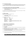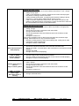
1
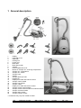
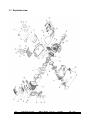
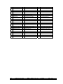
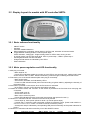
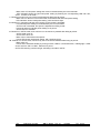
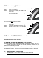
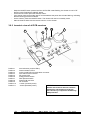
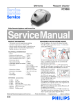
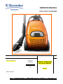
SERVICE MANUAL
VACUUM CLEANER
© E.H.P. Floor Care
Number of
publication
599 71 19-22
“Elara” electronic
vacuum cleaner
EN
Factory:
Edition: 2009-02
EN
Publication number
599 71 19-22
Rev. 01
02/2009
PR - 1/42
TABLE OF CONTENTS
1
2
3
4
5
6
7
8
General description .................................................................................................................................... 3
1.1 Exploded view....................................................................................................................................... 4
ACCESSIBILITY......................................................................................................................................... 6
Levels of Electronic Control...................................................................................................................... 28
3.1 Display Layout for models without remote controlled HBTN:............................................................. 28
3.1.1
Basic software functionality........................................................................................................ 28
3.1.2
Motor power regulation and LED-functionality........................................................................... 28
3.2 Display Layout for models with RF controlled HBTN: ........................................................................ 29
3.2.1
Basic software functionality........................................................................................................ 29
3.2.2
Motor power regulation and LED-functionality........................................................................... 29
3.3 Display Layout for models with Aeropro active system: ..................................................................... 31
3.3.1
Basic Software functionality ....................................................................................................... 31
3.3.2
Motor power regulation and LED-functionality........................................................................... 31
3.3.3
Brush motor functionality ........................................................................................................... 31
3.4 Nozzle power supply interface............................................................................................................ 32
3.5 Brush nozzle PCB 230V/110V active remote..................................................................................... 32
3.6 Standby indication (for both RF and active versions)......................................................................... 32
3.6.1
Reprogramming RF remote controller ....................................................................................... 32
3.6.2
Isometric view of all PCB-versions ............................................................................................ 33
3.7 Auto function, pressure sensor PCB (position 014D)......................................................................... 34
3.7.1
Functional description ................................................................................................................ 34
PCB Power Module (position 014A)......................................................................................................... 35
4.1 Introduction ......................................................................................................................................... 35
4.2 Connection for control unit.................................................................................................................. 35
4.3 Low Current Power Module ................................................................................................................ 36
4.3.1
Power supply design low current power module ....................................................................... 36
4.3.2
Electrical specification................................................................................................................ 36
4.4 High Current Power Module ............................................................................................................... 36
4.4.1
Electrical specification switched power supply .......................................................................... 36
RF transmitter........................................................................................................................................... 37
5.1 Introduction ......................................................................................................................................... 37
5.2 Design................................................................................................................................................. 37
5.2.1
Mechanical design, PCB shape................................................................................................. 37
5.3 LED indication..................................................................................................................................... 37
5.4 Changing the battery .......................................................................................................................... 37
Aeropro PCB 230V/110V motor ............................................................................................................... 38
6.1 Introduction ......................................................................................................................................... 38
6.2 PCB variants....................................................................................................................................... 38
6.3 Electrical overview .............................................................................................................................. 38
6.3.1
Functional description ................................................................................................................ 39
6.4 Description Remote control signal and handling ................................................................................ 39
6.5 Motor output........................................................................................................................................ 39
INDICATION & DIAGNOSTICS ............................................................................................................... 39
7.1 Filter and S-bag indicators.................................................................................................................. 39
7.1.1
Activation.................................................................................................................................... 39
7.1.2
Deactivation ............................................................................................................................... 40
7.2 Error handling ..................................................................................................................................... 40
7.2.1
General startup error.................................................................................................................. 40
7.2.2
Auto board error......................................................................................................................... 40
7.2.3
Aeropro PCB error handling....................................................................................................... 40
TROUBLE SHOOTING ............................................................................................................................ 41
EN
Publication number
599 71 19-22
Rev. 01
02/2009
PR - 2/42
1 General description
1
2
3
4
5
6
7
8
9
10
11
12
13
14
15
16
17
18
19
20
21
22
23
24
25
26
Display
Hepa filter cover
Hepa filter
Parking slot
Power cord
Motor filter
Motor filter holder
S-bag®
Dust compartment cover
Button for Aeropro 3in1, dust bag compartment
Aeropro 3in1 compartment
Aeropro 3in1 nozzle
Aeropro hose
Handle
Aeropro telescopic tube
Parking clip
Display for models with manual control
Aeropro classic handle
Aeropro ergo handle
Aeropro nozzle
Display for models with remote control
Aeropro remote control handle
Aeropro remote control handle for motorized nozzle
Aeropro motorized nozzle
Aeropro turbo nozzle*
Aeropro parketto nozzle*
* Accessories may vary from model to model.
EN
Publication number
599 71 19-22
Rev. 01
02/2009
PR - 3/42
1.1 Exploded view
EN
Publication number
599 71 19-22
Rev. 01
02/2009
PR - 4/42
Pos
Description
Pos
Description
Pos
Description
1
BASE
23
HOSE CONNECTION INNER
46
CLIP PARKING
2
MOTOR HOUSING
24
BUTTON FRONT COVER
47
ABSORBER FILTER LID
3
FRONT COVER
25
CORDWINDER LEVER
48
FRAME HOSE CONNECTION
4
BUTTON FRONT LID
26
DISPLAY BASE
49
SIDE FRAME LEFT
5
FRONT LID
27
FRONT WHEEL ROLL COMPLETE SOFT
50
PCB CONTROL UNIT
6
REAR COVER
28
FRONT WHEEL HOLDER
51
POWER SUPPLY UNIT AEROPRO
7
MOTOR COVER
29
SUSPENSION BLOCK DOMEL
52
SHAFT FRONT WHEEL ROLL
8
FILTER LID
30
FILTER HOLDER DISASTER FILTER
53
SHAFT FRONT WHEEL HOLDER
9
SUSPENSION RING
31
BEARING REAR WHEEL
54
CORDWINDER
10
DISPLAY WINDOW
32
SHAFT REAR WHEEL
56
FILTER HEPA
11
PEDAL CW
33
LEVER ON-OFF
57
POWER MODULE PCB
12
PEDAL ON/OFF
34
BUMPER RIGHT HANDLE
59
MOTOR FAN UNIT
13
BUTTON MIN/MAX
35
SEALING HEPA FILTER
63
MULTITOOL
14
REAR WHEEL
36
NO BAG SAFETY DEVICE
65
PCB AUTOFUNCTION
15
REAR WHEEL COMPLETE
38
ABSORBER MOTOR HOUSING
66
SPRING FRONT COVER BUTTON
16
REAR WHEEL COVER
39
SEALING FRONT LID
67
SPRING NO BAG SAFETY DEVICE
17
BUMPER LEFT HANDLE
40
ABSORBER MOTOR COVER
68
SPRING BUTTON FRONT LID
18
BUMPER HANDLE UPPER
41
FIXATION CORDWINDER
69
SPRING CONTROL PEDALS
19
HANDLE TRANSPARENT
42
COVER CORDWINDER
70
SPRING BUTTON POWER REGULATOR
20
SIDE FRAME RIGHT
43
COVER MIN/MAX
71
SPRING FRONT COVER POP-UP
21
HOSE CONNECTION OUTER
44
HOLDER AEROPRO CONTACT PLATE
72
SPRING cord winder
22
DUST COMPARTMENT
45
GRIP HANDLE
73
SPRING Spring cw lever
EN
Publication number
599 71 19-22
Rev. 01
02/2009
PR - 5/42
2
ACCESSIBILITY
The following chapter follows a disassembling process that step by step will allow the Technician to
completely dismount the vacuum cleaner. Tags have been added to help finding quickly the needed item to
be removed quickly.
The following sections are outlined:
- Dust bag cover and compartment
- Display cover
- PCB Display/Switch
- Top cover
- Housing
- Cord winder
- Handle
- Wheels
- Power module and power supply unit Aeropro
- Motor
- HBTN
ATTENTION:
Boards and electronic devices could be damaged by electrostatic discharges.
Don’t touch any components without any ESD protection.
EN
Publication number
599 71 19-22
Rev. 01
02/2009
PR - 6/42
Dust bag cover and compartment
Release the two rear tabs
of the grill filter
EN
Completely detach the grill filter
Remove the sponge
Remove the Hepa filter
Press the lock covers
Open the dust bag cover
Lift up the lock cover of the lid
Publication number
599 71 19-22
Rev. 01
02/2009
PR - 7/42
EN
Release the right anchor of the dust
bag cover
Release the left anchor
Detach the lock using a fine-tipped
screwdriver
Carefully detach this part
Remove completely the part
Remove the spring
Detach the lock using a fine-tipped
screwdriver
Carefully detach this part
Publication number
599 71 19-22
Rev. 01
02/2009
PR - 8/42
Release the right anchor of
the lid accessory
Release the anchor and remove
the lid accessory
EN
Publication number
Remove the spring from the dust bag
cover
599 71 19-22
Rev. 01
02/2009
PR - 9/42
Display cover
Detach the side cover using a finetipped screwdriver
Detach the side cover using a finetipped screwdriver
EN
Lift up the display cover
Remove completely the display cover
Detach the ON/OFF button lever
Detach the ON/OFF button using a
fine-tipped screwdriver
Detach the cord winder button using a
fine-tipped screwdriver
Publication number
599 71 19-22
Rev. 01
02/2009
PR - 10/42
Detach from the outside the power
button using a fine-tipped screwdriver
Remove the springs from the buttons
Detach from the inside the power
button using a fine-tipped screwdriver
EN
Publication number
Remove completely the power button
599 71 19-22
Rev. 01
02/2009
PR - 11/42
PCB Display/Switch
Detach the pressostat hose
Remove the PCB with the
reflector on it
Detach the PCB supply cable
Detach the reflector tab from the board
using a fine-tipped screwdriver
ATTENTION:
Boards and electronic devices could be
damaged by electrostatic discharges.
Don’t touch any components without any
ESD protection.
Detach the reflector tab from the board
using a fine-tipped screwdriver
EN
Publication number
599 71 19-22
Rev. 01
02/2009
PR - 12/42
Top cover
EN
Remove the screws that fix the top
cover
Detach the top cover using a finetipped screwdriver
Detach the top cover using a finetipped screwdriver
Detach the top cover using a finetipped screwdriver
Detach the top cover using a finetipped screwdriver
Detach the top cover using a finetipped screwdriver
Detach the top cover using a finetipped screwdriver
Detach the top cover using a finetipped screwdriver
Publication number
599 71 19-22
Rev. 01
02/2009
PR - 13/42
Remove completely the top cover from
the back
EN
Publication number
Remove completely the top cover from
the front
599 71 19-22
Rev. 01
02/2009
PR - 14/42
Housing
Remove the seven screws that fix the
housing of the cleaner
Remove the gasket from its site
Remove the filter from the holder
Remove completely the holder of
motor filter using a fine-tipped
Lift up the complete housing of the
cleaner keeping firmly down
EN
Publication number
599 71 19-22
Rev. 01
02/2009
PR - 15/42
Cord winder
Detach the cord winder button lever
using a fine-tipped screwdriver
Remove completely the cord winder
button pin
Remove the screws that keep the cord
winder assy
Remove the screws that keep the cord
winder assy
Remove the screw from the cord
winder cover
Lift up the cord winder cover
Detach the pressostat hose
Remove the cord winder cover
EN
Publication number
599 71 19-22
Rev. 01
02/2009
PR - 16/42
Remove completely the cord winder
EN
Publication number
599 71 19-22
Rev. 01
02/2009
PR - 17/42
Handle
Detach the left handle cover using a
fine-tipped screwdriver
EN
Remove completely the left handle
cover
Detach the right handle cover using a
fine-tipped screwdriver
Detach the right handle cover using a
fine-tipped screwdriver
Remove completely the right handle
cover
Remove the screw on the right side
Remove the screw on the left side
Publication number
599 71 19-22
Rev. 01
02/2009
PR - 18/42
Detach the internal rubber part of the
handle using a fine-tipped screwdriver
Detach the internal rubber part of the
handle using a fine-tipped screwdriver
Detach the internal rubber part of the
handle using a fine-tipped screwdriver
EN
Remove completely the internal rubber
part using a fine-tipped screwdriver
Remove the two screws on the front
part of the handle
Detach the locking pin on the handle
assy using a fine-tipped screwdriver
Separate the two parts of the handle
Remove the third part of the handle
Publication number
599 71 19-22
Rev. 01
02/2009
PR - 19/42
Wheels
EN
Detach the wheel covers using a finetipped screwdriver
Remove the screws; reach them
through the holes on the wheel
Remove the locking clip on the wheel
shaft
Detach the two clips on the axe using
a fine-tipped screwdriver
Remove completely the wheel shaft
Remove completely the axe from the
wheel
Remove the front wheel using a finetipped screwdriver
Remove the screws that fix the metal
plate to the structure
Publication number
599 71 19-22
Rev. 01
02/2009
PR - 20/42
Remove the screws that fix the metal
plate to the structure
EN
Publication number
599 71 19-22
Rev. 01
02/2009
PR - 21/42
Power module and power supply unit Aeropro
Detach the connectors using a finetipped screwdriver
Detach the connection
Detach the pressostat hose
EN
Detach the connectors using a finetipped screwdriver
Detach the connection
Detach the power module PCB using
a fine-tipped screwdriver
Detach the power supply unit Aeropro
using a fine-tipped screwdriver
Publication number
599 71 19-22
Rev. 01
02/2009
PR - 22/42
Motor
Detach the pressostat hose
Remove the screws that keep joined
the two housing
Remove the screws that keep joined
the two housing
Separate the two housing
Lift up the blower seal
Remove completely the blower seal
Remove completely the motor
EN
Publication number
599 71 19-22
Rev. 01
02/2009
PR - 23/42
Remove the absorber outer filter
Remove the motor’s cover
EN
Publication number
599 71 19-22
Rev. 01
02/2009
PR - 24/42
HBTN
Nozzle
Telescope tube
Bent end
Remove the screw using a torx
screwdriver
Remove the screw using a torx
screwdriver
Detach the top cover
Remove 3 screws using a fine-cross
screwdriver
Detach the complete brush lever
system
EN
Publication number
599 71 19-22
Rev. 01
02/2009
PR - 25/42
Detach the lever from the cover
Detach the wheel cover using a finetipped screwdriver
Remove the screw using a fine-cross
screwdriver
Remove 2 screws using a fine-cross
screwdriver
EN
Publication number
Detach the hose from the brush
599 71 19-22
Rev. 01
02/2009
PR - 26/42
Detach the cover from the hose
Detach the remote control using a
fine-tipped screwdriver
Detach the cover using a fine-tipped
screwdriver
EN
Publication number
599 71 19-22
Rev. 01
02/2009
PR - 27/42
3 Levels of Electronic Control
3.1 Display Layout for models without remote controlled HBTN:
3.1.1 Basic software functionality
-
ON/OFF switch
Soft-start, function according to chapter “Softstart and motor power change”.
Automatic 50/60Hz detection.
When started, raise power to maximum power.
( + ) increase motor power, one press increase power with one step. After maximum power has been
reached, the power stays in maximum power independent further activations of the “+” button.
( - ) decrease motor power, one press decrease power with one step. After minimum power has
been reached, the power stays in minimum power independent further activations of the “-” button.
5-step power regulation.
Power indication by one of five LED indicating actual power step.
S-bag and Filter status are indicated by two LED:s.
Failure indication.
3.1.2 Motor power regulation and LED-functionality
1. Main plug connected:
- Motor shall be off.
- Power LED:s indicates standby by turning on each LED for 0,5 seconds each, “walking light”.
Order should be from “Min” to “Max”.
2. First start (after main plug is connected):
- Motor power starts in Max power position.
- LED indicates “Max” position, with continuous light.
3. Power setting is changed by “+” or “-“ button:
- Motor power steps up or down.
- LED indication follows the setting of the motor power, with continuous light.
4. Cleaner is turned off by On/Off switch:
- Motor turns off; last power setting is remembered by the microcontroller.
- LED indication shows the last used power setting by flashing the corresponding LED with 1Hz.
5. Cleaner is turned on by On/Off switch after being at point 4:
- Motor turns on, and starts at the last used power setting.
- LED indication shows used power setting, with continuous light.
EN
Publication number
599 71 19-22
Rev. 01
02/2009
PR - 28/42
3.2 Display Layout for models with RF controlled HBTN:
3.2.1 Basic software functionality
-
ON/OFF switch
Soft-start
Automatic 50/60Hz detection.
When started from unplugged, cleaner starts in AUTO mode, otherwise in last used mode.
Toggle between cleaning modes, 5 manual power steps.
Power indication, “fading light”. 6 light intensity levels for LED:s when running in auto.
In manual mode, one LED per power level. LED1 in power step 1, LED2 in power step 2..
AUTO lightened when function activated.
S-bag and Filter status are indicated by two LED:s.
Failure indication.
3.2.2 Motor power regulation and LED-functionality
1. Main plug connected:
- Motor shall be off.
- Power LED:s indicates standby by turning on each LED for 0,5 seconds each, “walking light”.Order
should be from “Min” to “Max”. AUTO LED showing continuous light, indicating next start in Auto.
2. First start by one of the On/Off switches (after main plug is connected):
- Motor power starts.
- Auto function activated, and indicated by LED:s.
- Power bar LED indicates actual power used according to ignition table by adjusting the intensity of
the power LED:s.
3. Auto button is pressed on the remote, when AUTO-function is activated:
- No change in function, AUTO-function shall still be activated.
4. Cleaner is in AUTO-mode, and “min/max“ on the remote is pressed for the first time since main plug was
connected:
- AUTO-mode turns off.
- AUTO LED:s turns off.
- Motor runs to minimum power.
- Power LED indicates minimum power step (same power step split as for level 1).
5. Cleaner is in manual mode and “min/max“on the remote is pressed:
- Power steps up, same power split as for level 1 (5 manual power steps).
- If power step 1 (minimum power) the power changes to maximum power. (Power order shall be 12-3-4-5-1-2-3-4-5-1 a.s.o. where 1 is minimum and 5 is maximum power).
- Actual power step is indicated by corresponding LED (same functionality as the power indication for
level 1).
6. Cleaner is in manual mode and turned off by one of the ON/OFF buttons:
EN
Publication number
599 71 19-22
Rev. 01
02/2009
PR - 29/42
- Motor turns off; last power setting and mode is remembered by the microcontroller.
- LED indication shows the last used power setting by flashing the corresponding LED with 1Hz,
same function as for level 1.
7. Cleaner is turned on by one of the On/Off switches after being at point 6:
- Motor turns on and run into manual mode, and starts at the last used power setting.
- LED indication shows used power setting, with continuous light.
8. Cleaner is in manual mode and AUTO switch on the remote is activated:
- Last manual power setting is remembered by the microcontroller.
- AUTO mode is activated, and power is adjusted according to that.
- Power bar starts to indicate power setting as in point 2.
- AUTO LED:s is activated.
9. Cleaner is in AUTO-mode, and “min/max“ on the remote is pressed after being at point 8:
- AUTO-mode turns off.
- AUTO LED:s turns off.
- Motor runs to last manual used power..
- Power LED shows used power setting, with continuous light.
10. Cleaner is in AUTO-mode, turned off by one of the On/Off switches after being at point 8:
- Motor turns off.
- Power LED:s indicates standby by turning on each LED for 0,5 seconds each, “walking light”. Order
should be from “Min” to “Max”. Same as for point 1.
- AUTO LED showing continuous light, indicating next start in AUTO.
EN
Publication number
599 71 19-22
Rev. 01
02/2009
PR - 30/42
3.3 Display Layout for models with Aeropro active system:
3.3.1 Basic Software functionality
-
ON/OFF switch
Soft-start
Automatic 50/60Hz detection
When started from unplugged, cleaner starts in AUTO mode, otherwise in last used mode.
Toggle between cleaning modes, 5 manual power steps.
Power indication, “fading light”. 6 light intensity levels for LED:s when running in auto.
In manual mode, one LED per power level. LED1 in power step 1, LED2 in power step 2..
AUTO lightened when function activated.
S-bag and Filter status are indicated by two LED:s.
Failure indication.
3.3.2 Motor power regulation and LED-functionality
Same functionality as for the RF-controlled machine.
3.3.3 Brush motor functionality
It is not possible to start the brush motor when the vacuum cleaner motor is turned off. If the cleaner
is turned off by one of the On/Off switches, the brush motor also turns off.
If the cleaner are turned off by one of the On/Off switches, the brush motor status is saved by the
microcontroller, and when started again it reloads the status of the brush motor (on or off).
EN
Publication number
599 71 19-22
Rev. 01
02/2009
PR - 31/42
3.4 Nozzle power supply interface
For vacuum cleaners with AUTO mode function:
button 1
button 2
4
turns on or off the cleaner
turns on or off the nozzle motor (handled by the
Aeropro PCB)
turns on the cleaner into AUTO mode
turns on the cleaner into manual mode and toggles
the manual 5 power steps
button 3
button 4
3
2
1
For vacuum cleaners without AUTO mode function:
button 1
button 2
turns on or off the cleaner
turns on or off the nozzle motor (handled by the
Aeropro PCB)
increases the cleaner power in up to 5 power steps
decreases the cleaner power in up to 5 power steps
button 3
button 4
4
3
2
1
3.5 Brush nozzle PCB 230V/110V active remote
The remote control for the Aeropro 230V/110V active system are a two wire connected PCB
assembled in the cleaners bent end. From the remote control it is possible to control the cleaner functions.
Note: PCB working with live voltage – 230/110V.
3.6 Standby indication (for both RF and active versions)
When the main is connected, and the cleaner is in standby mode. This is indicated by “walking light”
on the power bar, which is also the indication for that when the cleaner is started it will start in “Auto mode”.
Also when in AUTO stand by mode, the “AUTO LED”:s are fully lightened to show that when the
cleaner is turned on, it will start in AUTO mode.
If turned off when running in AUTO mode, the power bar shall show “walking light”, and the “AUTO”
LED:s shall be turned on.
If turned off in manual mode, the last indicated power shall start to flash with 1Hz. The “AUTO”
LED:s shall always be turned off, both when running in manual mode or when in stand by for manual mode.
3.6.1 Reprogramming RF remote controller
-
Press ON/OFF button on cleaner and keep it pressed while inserting the main plug.
EN
Publication number
599 71 19-22
Rev. 01
02/2009
PR - 32/42
-
Keep the ON/OFF button pressed until the AUTO LED:s start flashing, the cleaner is now in RF
learning mode. Release the ON/OFF button.
On the remote control press the ON/OFF button.
If the cleaner have received the new RF remote address the power bar will start flashing, indicating
that the learning process is finalized.
On the cleaner, press the ON/OFF button. The cleaner will now be in standby mode.
Start the cleaner either with the remote control or on the cleaner.
3.6.2 Isometric view of all PCB-versions
10
8
11
7
6
9
Position 1
Position 2
Position 3
Position 4
Position 5
Position 6
Position 7
Position 8
Position 9
Position 10
Position 11
Auto indication (2 white LED:s)
Power indication LED:s
Active nozzle PCB communication connector
Auto switch PCB connector
RF remote PCB
S-Bag pressure switch
Filter pressure switch
Power PCB connector
On-off switch
+ switch (increase power)
- switch (decrease power)
ATTENTION:
Boards and electronic devices could be
damaged by electrostatic discharges.
Don’t touch any components without any
ESD protection.
EN
Publication number
599 71 19-22
Rev. 01
02/2009
PR - 33/42
3.7 Auto function, pressure sensor PCB (position 014D)
Auto function is a function for automatically regulate the motor power depending on the air pressure.
To the control PCB a pressure switch/sensor PCB is connected. The control PCB senses that the auto board
is connected and activates the software for automatic power regulation.
The Auto PCB is connected to the Control unit PCB like below sketch:
If pressure PCB is not connected, this will be indicated on the display by flashing the AUTO LED:s
with 1 Hz.
3.7.1 Functional description
When the pressure is too high the pressure switch is activated, and the controller starts to decrease
the power. When the switch is inactivated, depending on to low pressure, the controller starts to increase the
motor power until the switch activates.
In normal auto mode this means that the motor power will oscillate around the pressure setting of the
pressure switch.
EN
Publication number
599 71 19-22
Rev. 01
02/2009
PR - 34/42
4 PCB Power Module (position 014A)
4.1 Introduction
Power module is intended as a module PCB for mainly vacuum cleaners from Electrolux Floor Care
& Small Appliances AB. The module is intended to consist of a Triac, triggering a motor, and a power supply
for additional connected electronic.
The component layout for the power module should look like below sketch:
1. Power Module PCB.
2. Connector main voltage
3. Alternative main power connector / main power out
4. Motor connector
5. Connector to control PCB
All different kinds of Power modules have the same configuration of connector configuration, simplifying
design, service and cross over.
4.2 Connection for control unit
To be able to control the power module a control unit is connected to the 5-pol connector, which also
power supplies the control unit with 5VDC.
The configuration for the connector is following:
1. Ground.
2. 5VDC, maximum current according to level of power module.
3. Zero cross signal, square wave that follows the main frequency (5V amplitude).
4. Reserved for TCO signal (temperature control signal). Not implemented on the PCB, only
reserved for the function.
5. Triac ignition signal from the control unit to the power module.
EN
Publication number
599 71 19-22
Rev. 01
02/2009
PR - 35/42
4.3 Low Current Power Module
The low current power module contains a capacitive power supply.
The low current power module can always be replaced by a high current power module, or International
power module (see parts lists).
4.3.1 Power supply design low current power module
The 5V power supply is of the type capacitive supply.
Principal schematic:
4.3.2 Electrical specification
Input voltage:
Output voltage:
Max output current:
230V / 50Hz.
5V
35mA@4,8V.
NOTE: Output voltage is not insulated from main voltage
4.4 High Current Power Module
The high current power module consists of a switched power supply for providing the logical voltage
with higher current output.
4.4.1 Electrical specification switched power supply
Input voltage:
Output voltage:
Max output current:
EN
85-265V / 50-60Hz.
5V ±5%
220mA.
Publication number
599 71 19-22
Rev. 01
02/2009
PR - 36/42
5 RF transmitter
5.1 Introduction
The RF transmitter is used as remote control for a vacuum cleaner powered by a 3V changeable
lithium cell. The transmitter uses the 433MHz band for transmitting data inside EU. With the transmitter it is
possible to turn the appliance on and off, and regulate the motor power. Estimated lifetime for the battery in
normal use is approximately 8-12 months.
5.2 Design
5.2.1 Mechanical design, PCB shape
SW1 – Auto function on/off
SW2 – Cleaner on/off
SW3 – Manual power step
5.3 LED indication
The assembled LED is intended to communicate the battery status to the user. When there is no
LED indication it is time for the user to change the battery. In normal condition (standby) the LED are
inactivated. If a button is pressed the LED activates for approximately 250 milliseconds.
5.4 Changing the battery
Change the battery when light indicator is not responding when pressing any button. Observe polarity of
battery.
EN
Publication number
599 71 19-22
Rev. 01
02/2009
PR - 37/42
6 Aeropro PCB 230V/110V motor
6.1 Introduction
Aeropro PCB 230V is a new PCB to support the drive of a 230VAC motor mounted in the Aeropro
nozzle. The motors continuously current consumption is maximum 1A. The PCB can also be used without
nozzle motor, and then only support a wired remote control between the cleaners bent end and the cleaners
control unit.
6.2 PCB variants
The 230V variant use single sided PCB. Low voltage variant (100V for USA, Japan) use double sided PCB
together with UL approved coating.
6.3 Electrical overview
Sketch:
EN
Publication number
599 71 19-22
Rev. 01
02/2009
PR - 38/42
6.3.1 Functional description
The Aeropro PCB is supplied with main voltage, dimensioned to be used with both 230V and 100V
main power. A capacitive power supply is used to supply the electronics with 5VDC. The motor speed and
motor status in the nozzle are controlled by a triac. The triac are controlled by the cleaners control unit.
6.4 Description Remote control signal and handling
The remote control is connected to connector on the Aeropro PCB. The remote control uses a two
wire connection to the Aeropro PCB, and is connected as following:
- KEY +5V analog signal.
- M2 GND. Note: live voltage potential.
The controller on the Aeropro PCB reads the analog signal level, and converts the signal to a frequency
output signal, which is communicated to the Elara control PCB.
6.5 Motor output
The on/off of the motor nozzle is controlled by a Triac.
The motor is also connected as follows
- M1 motor phase
- M2 motor neutral (shared with the GND for the remote control)
Nozzle motor status is following:
Plug in:
OFF
Switch cleaner on:
OFF or last status.
Switch cleaner off:
OFF
Auto on:
No change
Auto off (manual):
No change
Manual power toggle: No change
Nozzle on/off:
If nozzle motor is off and cleaner motor running – turn it on
Nozzle on/off:
If nozzle motor is on and cleaner motor running – turn it off
Cleaner motor is off:
Always off.
7 INDICATION & DIAGNOSTICS
7.1 Filter and S-bag indicators
7.1.1 Activation
The indicators are operated by the controller. If the pressure switches activates, this is indicated by
the indicator LED:s.
After 2 seconds activation the corresponding LED will light up for 1 second, and after additional 57
seconds the corresponding LED will start to indicate
continuously.
During this time delay the pressure switch must not be deactivated. If it is deactivated, there will be a
new 60 second delay when activated next time.
The LED:s will continue to indicate after the cleaner is turned off and in standby mode.
At first start, after the main plug is connected, the S-BAG and FILTER indicator will turn on for one
second,
indicating that the LED:s is working.
EN
Publication number
599 71 19-22
Rev. 01
02/2009
PR - 39/42
7.1.2 Deactivation
To deactivate the LED indicator after activation this can be made in three ways. First is to disconnect
and reconnect the main connector.
Also this can be made by turning off the cleaner, turn it on again and keep the on/off button pressed
for 5 seconds.
At last when turned on after being activated, and running without the actual pressure switch is
activated for 30 seconds.
7.2 Error handling
7.2.1 General startup error
If the micro controller doesn’t receive any signal, the triac triggering is turned off, and the power
LED:s start to flash with 1 Hz. No other functions are activated. To start the cleaner again, the main plug
must be disconnected and connected again.
7.2.2 Auto board error
On RF- and active versions, if the auto control PCB is missing, both bag and filter LED starts to flash
with 1 Hz. It will still be possible to run the cleaner in manual mode. If either the filter or the bag switch is
activated, this LED will light continually according to description in chapter “Filter and S-bag indicators”, while
the inactivated LED will continue to flash.
7.2.3 Aeropro PCB error handling
If the control unit receives an error signal from the Aeropro PCB, or no signal at all, the cleaner motor
stops and a signal sent to the Aeropro PCB to stop
the nozzle motor. AUTO LED:s indicating failure by
flashing with 1 Hz if no signal is received. If error signal, this is indicated as a normal on/off –
“walking light”.
EN
Publication number
599 71 19-22
Rev. 01
02/2009
PR - 40/42
8 TROUBLE SHOOTING
Problem
Checks
Cleaner without remote:
- Investigate if the plastic knob reaches the ON/OFF switch on the PCB.
- Replace the control unit (display PCB)
Cleaner doesn’t start;
if standby is indicated
on display
Cleaner with radio remote:
- Investigate if both ON/OFF (cleaner and remote) is not working.
If remote ON/OFF working, but not cleaner ON/OFF:
- Investigate if the plastic knob reaches the ON/OFF switch on the PCB.
- Replace the control unit (display PCB).
If cleaner ON/OFF working, but not remote ON/OFF:
- Investigate if the LED on the remote indicates transmission. If not, change
battery and try again.
- If still no LED indication on remote, change remote control and reprogram
the cleaner according to above instruction.
- If LED indicates transmission, try replacing the remote according to above
instruction. If cleaner starts, replace the RF remote control.
- If still no function, replace the control unit in the cleaner. Be aware of the
position of the radio antenna. If replacing the control unit this has to learn the
RF-remote address according to above description.
If no reaction on any ON/OFF buttons: replace the control unit (display PCB).
Cleaner with active motor nozzle:
- Investigate if both ON/OFF (cleaner and remote) are not working.
If remote ON/OFF working, but not cleaner ON/OFF:
- Investigate if the plastic knob reaches the ON/OFF switch on the PCB.
- Replace the control unit (display PCB).
If cleaner ON/OFF working, but not remote ON/OFF:
- Check the bent end, test with another HBTN. If the cleaner starts, change.
- Check wiring from hose connection to 2G active PCB.
- Change 2G active PCB, test.
- Check wiring between 2G active PCB and control unit for failure or bad
connection.
- Change the control unit.
If no reaction on any ON/OFF buttons: replace the control unit (display PCB).
Cleaner doesn’t start;
no indication on
display
-
Cleaner doesn’t start;
display shows normal
running mode
Not possible to change
power level
EN
-
Check if the Power module PCB gets main voltage.
Check communication wire between Power module and control unit for
failure or bad connection.
Change the control unit.
Change the Power module.
Check motor voltage, if no voltage, check the electronics as below, else
check motor TCO and motor.
Check communication wire between Power module and control unit for
failure or bad connection.
Change the control unit.
Change the Power module.
Cleaner without remote:
Investigate if the plastic knob reaches the +/- switches on the PCB.
Replace the control unit (display PCB).
Publication number
599 71 19-22
Rev. 01
02/2009
PR - 41/42
Cleaner with radio remote:
- Investigate if the LED on the remote indicates transmission. If not, change
battery and try again.
- If still no LED indication on remote, change remote control and reprogram
the cleaner according to above instruction.
- If LED indicates transmission, try replacing the remote according to above
instruction. If cleaner starts, replace the RF remote control.
- If still no function, replace the control unit in the cleaner. Be aware of the
position of the radio antenna. If replacing the control unit this has to learn the
RF-remote address according to above description.
Cleaner with active motor nozzle:
- Check the bent end, test with another HBTN. If possible to change power
setting, change.
- Check wiring from hose connection to 2G active PCB.
- Change 2G active PCB, test.
- Check wiring between 2G active PCB and control unit for failure or bad
connection.
- Change the control unit.
If the power regulation works for the first minutes after start, and then stops
working. Motor seems to run only in maximum speed.
- Check the cooling system to the Power module (tube, cooling house, tube
connection to dust compartment).
- Change the Power module PCB.
Auto function doesn’t
work properly
Filter or S-bag
indicator always or
never indicates
Nozzle motor doesn’t
start or
stop on active system
LED:s on nozzle
doesn’t light,
but nozzle motor is
running
EN
-
Check tube connection between hose connection and Auto PCB.
Check Auto PCB:s communication cable connection on the Control unit PCB
(display).
Change Auto PCB.
Change Control unit PCB (Display).
-
Check the bag or filter if replacement is needed.
Check the tubes to the pressure switches on the control unit PCB (display).
Change the control unit PCB (display).
-
-
Check the bent end, test with another HBTN. If possible to start nozzle
motor, change.
Check wiring from hose connection to 2G active PCB.
Change 2G active PCB, test.
Check wiring between 2G active PCB and control unit for failure or bad
connection.
Change the control unit.
-
Change nozzle electronic
-
-
Publication number
599 71 19-22
Rev. 01
02/2009
PR - 42/42