1
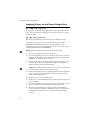
A5 Quick Install Guide Cover
x900 Series Switch
Removable Power Supply and Fan
Installation Guide
AT-PWR01
AT-PWR02
AT-FAN01
C613-04057-00 REV D
Removable Power Supply and Fan
Removable Power Supply and Fan Installation Guide for x900 Series Switch,
Document Number C613-04057-00 REV D
© 2003-2006 Allied Telesis, Inc. All rights reserved. No part of this publication
may be reproduced without prior written permission from Allied Telesis, Inc.
Allied Telesis, Inc. reserves the right to change specifications and other
information in this document without prior written notice. The information
provided herein is subject to change without notice. In no event shall Allied
Telesis, Inc. be liable for any incidental, special, indirect, or consequential
damages whatsoever, including but not limited to lost profits, arising out of or
related to this manual or the information contained herein, even if Allied Telesis,
Inc. has been advised of, known, or should have known, the possibility of such
damages.
All company names, logos, and product designs that are trademarks or
registered trademarks are the property of their respective owners.
2
Installation Guide
Contents
Models Covered by this Guide ...................................................................................... 4
Compatible Switches ....................................................................................................... 4
Package Contents ............................................................................................................. 4
Installing a Power Supply Unit ....................................................................................... 5
Applying Power to the Power Supply Unit ................................................................. 8
Checking LEDs .................................................................................................................. 9
Troubleshooting .............................................................................................................. 10
Where to Find More Information .............................................................................. 10
Standards .......................................................................................................................... 11
EC Declaration of Conformity .................................................................................... 12
3
Removable Power Supply and Fan
Models Covered by this Guide
This document describes how to install the following models:
■
AT-PWR01 PSU, either AC or DC power supply unit
■
AT-PWR02 PSU, AC power supply unit only
■
AT-FAN01, fan-only module
Compatible Switches
The following table shows which models of PSUs and FOMs are appropriate for
individual switches.
Switch
PWR01
PWR02
FAN01
AT-8948 and x900-48FE
!
!
!
AT-9924T, AT-9924SP, AT-9924T/4SP
!
!
!
AT-9924Ts and x900-24X
!
!
Package Contents
Each switch is supplied with a single power supply unit (PSU), either AC or DC.
Depending on the model, the switch also has a fan-only module (FOM) or a
blanking panel.
■
The AT-8948, AT-9924Ts, x900-24X, and AT-9924T/4SP switches have a
PSU and a FOM installed.
■
The x900-48FE, AT-9924T, and AT-9924SP switches have a PSU and a
blanking panel installed.
The following items are included with each factory-installed PSU. Contact your
authorised distributor or reseller if any are damaged or missing.
4
■
one AC power cord (AC model)
■
one power cord retaining clip (AC model)
■
one warranty card
Installation Guide
The following items are included with PSUs purchased separately:
■
one AC power cord (AC model)
■
one power cord retaining clip (AC model)
■
one Installation Guide
■
one warranty card
The following items are included with each FOM purchased separately:
■
one Installation Guide
■
one warranty card
Installing a Power Supply Unit
Warning All AC and DC versions of this equipment must be earthed.
Do not install an AC PSU and a DC PSU in the same switch chassis.
If you remove a PSU or FOM from the switch, immediately replace it or cover
the bay with a blanking panel. This prevents dust and debris from entering the
chassis and maintains proper airflow in the switch.
AC power supply unit specifications
Important information for service personnel:
■
CAUTION: double pole/neutral fusing
■
the rating of fuses FH101 and FH102 is 250 V, 5 A (AT-PWR01 only)
DC supply cable and power supply specifications
■
three-core cable is required
■
minimum core size: 3.3 mm2 (12 AWG) high strand count copper wire
■
minimum cable rating: 600 V, 90 degrees Celsius
DC power supply specifications
■
40 to 60 V, 48 V nominal
■
supports either positive grounded or negative grounded operation
■
a 15 Amp certified/listed circuit breaker is required for circuit protection
5
Removable Power Supply and Fan
Installing a power supply unit or fan-only module
Before you begin:
■
Read the safety information for the switch.
Safety information is available in the Installation and Safety Guide that is on
the CD-ROM for the switch. Or you can download this document from
www.alliedtelesis.com/support/software.
■
Gather necessary tools and equipment.
You may need a Phillips #2 screwdriver to adjust the retaining screws on a
PSU or FOM.
To install a DC version of the PSU, you need an appropriate DC power
source, DC supply cable, ring connectors, and a crimp tool.
■
Verify the package contents if you have not already done so.
See “Package Contents” on page 4. Contact your authorised distributor or
reseller if items are damaged or missing.
1.
Unpack the power supply unit.
Caution Follow correct anti-static procedures when installing either a PSU
or FOM. Failure to do so could damage the PSU, FOM, or switch. If you are
unsure about correct procedures, contact your authorised distributor or
reseller.
While observing Electro Static Discharge (ESD) precautions, remove the
PSU or FOM from its packing material in an anti-static environment.
2.
Disconnect the power supply from the power supply unit.
Warning Disconnect the power cord before removing the PSU.
For AC models, turn off the main power supply to the PSU and disconnect
the power cord.
For DC models, push the Run/Standby control and release it to the Off
position using a small diameter pin. When the Run/Standby control is not
depressed, it is off. Disconnect the supply cable wires from the circuit
breaker.
3.
For AC models only, install the power cord retaining clip.
There is one retaining clip for the AC power inlet on the PSU.
6
Installation Guide
4.
Remove the current power supply unit, fan-only module, or
blanking panel from the switch.
Loosen the two captive Phillips screws until the they are fully loosened.
Switch
PSU
Captive screw
Captive screw
PSU2
If a PSU or FOM is in the bay, slide it out slowly and carefully. Support the
device from underneath as you remove it to prevent it from falling.
When you have one PSU for AT-9924T and AT-9924SP models, it must be
installed in bay 2 to optimise cooling.
Caution Cover empty bays because dust and debris could overheat or
damage the PSU and switch.
5.
Insert another power supply unit.
Caution Keep the PSU or FOM in straight alignment and insert it slowly.
Forcing a misaligned PSU or FOM is likely to damage both the chassis and
PSU or FOM.
Slowly and carefully slide the PSU or FOM into the power supply bay.
Firmly press the PSU or FOM until the faceplate engages, or nearly engages,
the chassis.
6.
Secure the power supply unit.
Tighten the two captive Phillips screws on the faceplate of the PSU or FOM
(see figure in Step 4).
7
Removable Power Supply and Fan
Applying Power to the Power Supply Unit
For an AC power supply unit
To apply power to the PSU, plug the AC power cord that is provided into the
power inlet on the faceplate of the PSU. Then connect the power cord to the
main power supply.
For a DC power supply unit
Only trained and qualified personnel should connect a DC power supply.
For centralised DC power connection, the switch should be installed in
restricted access areas only (such as dedicated equipment rooms or
equipment closets) in accordance with Articles 110-16, 110-17, and 110-18 of
the National Electrical Code, ANSI/NAPA 70.
Warning Ensure that the power cable is not live before starting.
1.
Remove the transparent protective terminal cover.
2.
Strip the supply cable wires to expose 7.5mm (0.31 in.) of bare conductor.
Terminate the wire with a nylon insulated solderless ring tongue terminal,
JST FN5.5-5 or equivalent, using a crimp tool.
3.
Connect the ground wire to the ground terminal. Use the diagram on the
rear panel of the switch to identify terminals. Tighten the terminal to
between 2.4 and 4.0 Nm (21.3 and 35.4 lbf in).
Caution Check that the PSU terminals are wired to the correct polarity.
You will damage the PSU if you incorrectly connect it.
8
4.
Connect the positive feed to the + (positive) terminal and the negative feed
to the - (negative) terminal. Tighten the terminals to between 2.4 and
4.0 Nm (21.3 and 35.4 lbf in).
5.
Ensure there are no exposed cable strands.
6.
Replace the cover. You must replace the transparent plastic terminal cover
before continuing.
7.
Secure the supply cable to the rack framework or a similar object to ensure
that connections are isolated from any force applied to the cable.
8.
Ensure the circuit breaker for the supply circuit and the Run/Standby
control on the PSU are off. Use a small diameter pin to press and release
the Run/Standby control so that it is not pushed in (which is the Off
position).
Installation Guide
9.
Connect the supply cable wires to the circuit breaker.
10. Turn on the PSU by pushing in the Run/Standby control with a small
diameter pin.
Checking LEDs
LEDs indicate the operational status on the faceplate of each PSU and on the
front panel of the switch.
After you have inserted the PSU and powered on the switch, check the LEDs for
correct operation by using the following tables.
Table 1: LEDs on the power supply unit and fan-only module
LED
State
Description
Fault
Red
The temperature of the PSU has exceeded the limit of
75º C (167º F), or the FOM has failed.
PWR
Green
A PSU is installed in the switch and is receiving power.
FOMs do not have this LED.
Table 2: LEDs on the switch reporting PSU status
LED
State
Description
PSU 1
Green
PSU 1 is installed and supplying power to the switch. The
voltage output is within specification.
Red
PSU 1 is installed in the switch and has exceeded its
recommended temperature threshold of 75º C (167º F),
or the fan has failed.
A FOM is installed in the switch and has failed.
The bay is empty. Applies to AT-8948, AT-9924T/4SP, and
AT-9924Ts switches since they require a FOM when
only one PSU is installed.
Off
A FOM is installed and operating at an acceptable speed.
For AT-9924T and x900-48FE switches, a blanking panel
is installed.
9
Removable Power Supply and Fan
Table 2: LEDs on the switch reporting PSU status (Continued)
LED
State
Description
PSU 2
Green
PSU 2 is installed and supplying power to the switch. The
voltage output is within specification.
Red
PSU 2 is installed in the switch and has exceeded its
recommended temperature threshold of 75º C (167º F),
or the fan has failed.
A FOM is installed in the switch and has failed.
The bay is empty. Applies to AT-8948, AT-9924T/4SP, and
AT-9924Ts switches since they require a FOM when
only one PSU is installed.
Off
A FOM is installed and operating at an acceptable speed.
For x900-48FE switches, a blanking panel is installed.
Troubleshooting
If the PSU does not function as expected:
■
check that all cable connections are correct and secure.
■
check that the standby switch has been pressed and is in the On position
(DC models).
■
check that the PSU is receiving the correct AC voltage (AC models).
■
if LEDs indicate a PSU fault, replace the PSU or have your authorised
distributor or reseller service it.
Additional troubleshooting information is in the Hardware Reference for the
switch.
Where to Find More Information
■
The Hardware Reference for your switch provides detailed information on
the switch and its hardware features.
■
The Software Reference for your switch provides detailed information to
configure the switch and its software.
■
The Installation and Safety Guide for your switch describes how to install
your switch and includes statutory and safety information.
You can download these documents from www.alliedtelesis.com.
10
Installation Guide
Standards
Products in this document meet the following standards:
Category
Approval Agency and Requirement
UL60950-1
CAN/CSA-C22.2 No. 60950-1-03
EN60950-1
AS/NZS 60950
Electromagnetic Compliance
FCC CFR47 Part 15 Class A
EN55022 Class A
VCCI Class A
AS/NZS CISPR22 Class A
CNS 13438 Class A
EN61000-3-2/3
Immunity
EN55024
U.S. Federal Communications Commission
RADIATED ENERGY
Note: This equipment has been tested and found to comply with the limits for a Class A digital device
pursuant to Part 15 of the FCC Rules. These limits are designed to provide reasonable protection
against harmful interference when the equipment is operated in a commercial environment. This
equipment generates, uses, and can radiate radio frequency energy and, if not installed and used in
accordance with this instruction manual, may cause harmful interference to radio communications.
Operation of this equipment in a residential area is likely to cause harmful interference in which case
the user will be required to correct the interference at his own expense.
Note: Modifications or changes not expressly approved by the manufacturer or the FCC can void
your right to operate this equipment.
Canadian Department of Communications
This Class A digital apparatus meets all requirements of the Canadian Interference-Causing
Equipment Regulations.
Cet appareil numérique de la classe A respecte toutes les exigences du Règlement sur le matériel
brouilleur du Canada.
11
Removable Power Supply and Fan
EC Declaration of Conformity
We:
ALLIED TELESIS LABS LIMITED
27 NAZARETH AVENUE
CHRISTCHURCH 8024
NEW ZEALAND
Declare under our sole legal responsibility that the following product meets the
safety, protection and conformity requirements of council directives 1999/5/EC
73/23/EEC and 89/336/EEC, as amended by 93/68/EEC, on the approximation of
the laws of member states relating to electromagnetic compatibility, electrical
safety and the mutual recognition of conformity of telecommunications terminal
equipment
AT-PWR01, AT-PWR02, and AT-PWR01-80 Power Supply Units
to which this declaration relates are in conformity with the following relevant
harmonized standards, the reference numbers of which have been published in
the Official journal of the European community.
EN55022: 1998
Information Technology Equipment—Radio disturbance
EN55024: 1998
Information Technology Equipment—Immunity
characteristics—Limits and methods of measurement.
EN60950-1: 2001
Information Technology Equipment including electrical
business equipment—General Requirements.
EN61000-3-2: 2000 Electromagnetic compatibility (EMC) - part 3-2: Limits for
harmonic current emissions (equipment input current up to
and including 16A per phase).
EN61000-3-3: 1995 Electromagnetic compatibility (EMC) - part 3-3: Limitation
of voltage fluctuations and flicker in low-voltage supply
systems for equipment with rated current up to 16A.
12
Name: John Shields
On behalf of the Manufacturer
Position: Managing Director
Signature:
Date: 1 March 2006