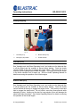
1
BG-250G11 & BG-250G13 Gas Powered Concrete Grinder Blastrac 6215 N. Aluma Valley Dr. Oklahoma City, OK 73121 1-800-256-3440 © Copyright Blastrac Revision (A) 12-23-04 FORWARD ISPC/Blastrac is pleased that you have selected this Diamond Grinding System for your surface preparation requirements. This environmentally safe, closedcycle, surface preparation machine has been designed and built for abrasive blast cleaning of horizontal surfaces. This manual has been prepared to assist the operator and the maintenance personnel in understanding the machine so that it may be operated in the most efficient manner and maintained in the best condition. Therefore, it is necessary that all personnel responsible for the operation and maintenance of the machine read the manual thoroughly. By following the instructions in this manual, this system can be easily and effectively operated, serviced and maintained by personnel assisted by a brief period of familiarization and training from a Blastrac technician. Before attempting to operate, service, or maintain the machine, the personnel should thoroughly familiarize themselves with the physical makeup of the machine, be familiar with the major systems of the machine, and have an understanding of its operation. The operating and maintenance personnel must obey all the warnings and safety precautions posted on the side of the machine and stated throughout this manual. Serious injury to personnel or severe damage to the equipment may result if the warnings and precautions are not followed, or through careless handling of this equipment. Initial operation and maintenance must be done cautiously. Extreme care should be taken when activating any control devices until the response of the machine and its various components are clearly understood. If you have any questions or problems in regard to the operation or capabilities of this Blastrac machine, please contact: ISPC/Blastrac 6215 Aluma Valley Drive Oklahoma City, OK 73121 405/478-3440 800/256-3440 or your nearest Service Center. i INTRODUCTION This manual has been prepared to assist the operator and maintenance personnel in understanding the machine so that it may be operated in the safest and most efficient manner and maintained in the best condition. Therefore, it is necessary that all personnel responsible for the operation and maintenance of the machine read and understand the manual. Before attempting to operate service or maintain the machine, the personnel should thoroughly familiarize themselves with the physical make-up of the machine. They should be familiar with the major components of the machine and have a general understanding of overall operations. The operating and maintenance personnel must obey all the warnings and safety precautions posted on the machine and stated throughout this manual. Serious injury to personnel or severe damage to the equipment may result if the warnings and precautions are not followed. You will be notified of any changes that occur after this manual is printed. We will send you manual revisions that should be inserted in the manual in accordance with instructions that will be forwarded with them. Receipt of Machine Examine the shipment carefully for possible damage that might have occurred while in transit. If any damage is noted, notify the transportation carrier immediately and advise ISPC/Blastrac. i ISPC/BLASTRAC WARRANTY POLICY This document is to be used as a guide in determining warranty policies and procedures for BLASTRAC products. It is to be used in determining whether a warranty is justified and also as a procedural guide in completing a BLASTRAC Warranty Claim form. Warranty Responsibility: The distributor or the end user must prepare a Machine Warranty Information Card when the machine is delivered. Failure to comply will make any and all warranties on this equipment null and void. Credit for warranty repairs will be given only after receipt of the WARRANTY CLAIM FORM, properly completed with all the required details. Submittal details are described later in this document. Warranty Policy: 1. Blastrac warrants its products against defects in material and workmanship under normal and proper use for a period of one hundred and eighty (180) days from the date of delivery; in the case of Rental Fleet Machines, date of assignment to Rental Fleet. Such warranty is extended only to the buyer who purchases the equipment directly from Blastrac or its authorized distributor. This warranty does not include expendable parts such as, but not limited to, blades, blast wheel, wear plats, liners and seals. 2. The obligation under this warranty is strictly limited to the replacement or repair, at Blastrac’s option, of machines and does not include the cost of transportation, loss of operating time, or normal maintenance services. 3. This warranty does not apply to failure occurring as a result of abuse, misuse, negligence, corrosion, erosion, normal wear and tear, alterations or modifications made to the machine without express written consent of Blastrac. 4. Warranty request must be submitted in writing within thirty (30) days after failure. 5. Written authorization to return merchandise under warranty must first be obtained from Blastrac. Warranty Policy (Continued) 6. Blastrac reserves the right to inspect and make the final decision on any merchandise returned under warranty. 7. Blastrac offers no warranty with respect to accessories, including but not limited to, engines, motors, batteries, tires and any other parts not manufactured by us but which the original manufacturer warrants. 8. Blastrac reserves the right to make product changes or improvements without prior notice and without imposing any obligation upon itself to install the same on its products previously sold. 9. The above warranty conditions can only be altered by Blastrac. Blastrac must confirm alterations in writing for each specific transaction. 10. Blastrac reserves the right to establish specific warranty terms for used or demo machines on an individual transaction basis. Invoices covering such merchandise will clearly state the provisions of the applicable warranty for each specific transaction. 11. WE DO NOT AUTHORIZE ANY PERSON, REPRESENTATIVE OR SERVICE OR SALES OUTFIT TO MAKE ANY OTHER WARRANTY OR TO ASSUME FOR US ANY LIABILITY IN CONNECTION WITH THE SALE OF OUR PRODUCTS OTHER THAN THOSE CONTAINED HEREIN. 12. UNDER NO CIRCUMSTANCES SHALL BLASTRAC BE LIABLE TO CUSTOMER OR ANY OTHER PERSON FOR ANY DIRECT, INCIDENTAL, OR CONSEQUENTIAL DAMAGES RESULTING FROM THE USE OF THE PRODUCT OR ARISING OUT OF ANY BREACH OF ANY WARRANTY OR FOR ANY SPECIAL OR CONSEQUENTIAL DAMAGES OF ANY CHARACTER, INCLUDING WITHOUT LIMITATIONS, DAMAGES FOR ANY LOSS OF GOODWILL, WORK STOPPAGE, OR ANY AND ALL OTHER COMMERCIAL DAMAGES OR LOSSES. 13. BLASTRAC MAKES NO OTHER WARRANTIES, EXPRESSED OR IMPLIED, INCLUDING, BUT NOT LIMITED TO, THE IMPLIED WARRANTIES OF MERCHANTABILITY AND FITNESS FOR A PARTICULAR PURPOSE WITH RESPECT TO THE BLASTRAC PRODUCTS SOLD PURSUANT THERETO. iii Operating Instructions Table of Contents BG-250G11/G13 Sections: Chapter 1: Technical Data 1.1 Rating ----------------------------------------------------------------------------------------------------------- 2 1.2 Unit specifications --------------------------------------------------------------------------------------------- 2 1.3 Operating range and correct usage ----------------------------------------------------------------------- 3 1.4 Machine type design ------------------------------------------------------------------------------------------ 3 1.5 Advise for operators of the machine ---------------------------------------------------------------------- 4 Chapter 2: Safety 2.1 Warnings and symbols --------------------------------------------------------------------------------------- 6 2.2 Organizational Measures------------------------------------------------------------------------------------- 9 2.3 Personnel selection and qualification ------------------------------------------------------------------- 10 2.4 Safety precautions applicable to some operating sequences ------------------------------------- 11 2.5 Special work instructions ----------------------------------------------------------------------------------- 12 2.6 Definition of the Maintenance Mode-------------------------------------------------------------------- 14 2.7 Possible dangerous aspects of the equipment-------------------------------------------------------- 15 2.8 Electrical-------------------------------------------------------------------------------------------------------- 15 Chapter 3: General 3.1 Range of application----------------------------------------------------------------------------------------- 17 3.2 Scope of supply----------------------------------------------------------------------------------------------- 17 3.3 Description of the machine--------------------------------------------------------------------------------- 18 3.4 Operating elements------------------------------------------------------------------------------------------ 19 3.5 The tools-------------------------------------------------------------------------------------------------------- 22 3.6 Care and Maintenance-------------------------------------------------------------------------------------- 23 Chapter 4: Transport 4.1 Unit specification --------------------------------------------------------------------------------------------- 25 4.2 Manual mode of moving the machine ------------------------------------------------------------------- 25 4.3 Transport with cranes or lifts ------------------------------------------------------------------------------ 26 4.4 Transport of the machine with vehicle ------------------------------------------------------------------ 27 Chapter 5: Initial Operation 5.1 Preparation for initial operation --------------------------------------------------------------------------- 29 5.2 Initial operation------------------------------------------------------------------------------------------------ 30 Chapter 6: Operation 6.1 Operation------------------------------------------------------------------------------------------------------- 35 6.2 Switching-off the machine---------------------------------------------------------------------------------- 37 6.3 Emergency shutdown -------------------------------------------------------------------------------------- 38 6.4 Safety shutdown---------------------------------------------------------------------------------------------- 38 6.5 Restarting after a fault--------------------------------------------------------------------------------------- 38 6.6 Procedures after lengthy down time --------------------------------------------------------------------- 39 Chapter 7: Maintenance 7.1 Recommendations ------------------------------------------------------------------------------------------- 41 7.2 Maintenance and inspection list -------------------------------------------------------------------------- 42 7.3 Repairing ------------------------------------------------------------------------------------------------------- 43 7.4 Grinding disc replacement / assembly ------------------------------------------------------------------ 44 7.5 Bearing Unit --------------------------------------------------------------------------------------------------- 45 7.6 Flexible coupling---------------------------------------------------------------------------------------------- 46 7.7 The V belt drive ----------------------------------------------------------------------------------------------- 47 7.8 The driving motor--------------------------------------------------------------------------------------------- 49 7.9 Additional maintenance ------------------------------------------------------------------------------------- 50 7.10 Spare parts ---------------------------------------------------------------------------------------------------- 50 7.11 Influences on the grinding pattern------------------------------------------------------------------------ 50 © Copyright Blastrac Revision (A) 12-23-04 Operating Instructions Table of Contents BG-250G11/G13 Chapter 8: Electrical 8.1 Directions for electrical engineering --------------------------------------------------------------------- 53 8.2 Electric circuits diagrams ----------------------------------------------------------------------------------- 54 Chapter 9: Troubleshooting 9.1 Grinder troubleshooting------------------------------------------------------------------------------------- 57 9.2 Electrical troubleshooting----------------------------------------------------------------------------------- 58 Chapter 10: Spare Parts 10.1 Spare parts B-250 G11/G13 ------------------------------------------------------------------------------ 60 List of Figures: Figure 3.1 – Description of the machine ------------------------------------------------------------------------------- 18 Figure 3.2 – Handgrip and Jack Stand Operating Lever ---------------------------------------------------------- 19 Figure 3.3 – Starting/ Stopping-------------------------------------------------------------------------------------------- 20 Figure 3.4 – The Tools ------------------------------------------------------------------------------------------------------ 22 Figure 4.1– Transport ------------------------------------------------------------------------------------------------------- 26 Figure 5.1 – Handgrip and Operating Lever -------------------------------------------------------------------------- 30 Figure 5.2 – Starting/ Stopping ------------------------------------------------------------------------------------------- 31 Figure 6.1 – Operation-Movement of machine ----------------------------------------------------------------------- 36 Figure 6.2 – Switching off machine -------------------------------------------------------------------------------------- 37 Figure 7.1 – Grinding disk replacement--------------------------------------------------------------------------------- 44 Figure 7.2 – Lubrication- bearing unit ----------------------------------------------------------------------------------- 45 Figure 7.3 – Flexible coupling -------------------------------------------------------------------------------------------- 46 Figure 7.4 – V- belt drive --------------------------------------------------------------------------------------------------- 47 Figure 7.5 – V- belt drive disassembly --------------------------------------------------------------------------------- 48 Figure 7.6 – Belt tension --------------------------------------------------------------------------------------------------- 49 ? For answers to your questions about this product, contact your local Distribution Representative or call: Blastrac 1-800-256-3440 or 1-405-478-3440 7 am – 6 pm, Mon-Fri (CST) Blastrac • 6215 Aluma Valley Dr. • Oklahoma City, OK 73121 USA © Copyright Blastrac Revision (A) 12-23-04 Operating Instructions Technical Data BG-250G11/G13 November 2004 Contents Chapter 1 1.1 Rating 1.2 Unit specifications 1.3 Operating range and correct usage 1.4 Machine type designation 1.5 Advice for operators of the machine Copyright Blastrac 1 Revision (A) 12-23-04 Operating Instructions Technical Data BG-250G11/G13 November 2004 1.1 Rating Unit / Designation: Blastrac Grinding machine Machine type: BG 250G11/G13 Manufacturer: Blastrac 6215 N. Aluma Valley Dr. Oklahoma City, OK 73121 1.2 Unit specifications Technical data: Grinding Machine BG-250G11/G13 Power consumption 11HP/13HP Connected loads 12V Tool diameter 10 in (250 mm) Working width 10 in (250 mm) Dust hose connection 3 in (75 mm) Recommended Filter unit Blastrac® Turbo-Vac II, Blastrac 1-13DC Noise Level 78 DBA Vibration Level < 2,5 ms² Copyright Blastrac 2 Revision (A) 12-23-04 Operating Instructions Technical Data BG-250G11/G13 November 2004 Dimensions: BG-250G11/G13 Length Width Height Weight 49.25 in (1250 mm) 24.50 in (620 mm) 39.38 in (1000 mm) 260/271 lbs (118/123 kg) 1.3 Operating range and correct usage The grinding machine BG-250G11/G13 is exclusively designed to grind horizontal surfaces. The machine may not be used for other purposes. The manufacturer will not be liable for damage or injury resulting from such incorrect usage. In these cases the user assumes all risks. 1.4 Machine type designation Machine Type – BG (Blastrac Grinder) Working Width – 250 (mm) Power Plant – G11 or G13 (11 HP or 13 HP Gasoline) Copyright Blastrac 3 Revision (A) 12-23-04 Operating Instructions Technical Data BG-250G11/G13 November 2004 1.5 Advice for operators of the machine When you use the grinding machine BG-250G11/G13 it is possible to exceed the allowed scale of sound level of 85 db(A). That sound level varies depending on the location. If the scale of sound level reaches 85 db(A) or more, the operators and the persons who work in the surroundings must wear noise protection. Pay attention that you always put down the machine on the kick stand if not grinding. If you put down the machine on the grinding disc, the flexible coupling will deform causing unequal wear of the tools and increased vibration level. Copyright Blastrac 4 Revision (A) 12-23-04 Operating Instructions Safety BG-250G11/G13 November 2004 Contents Chapter 2 2.1 Warnings and symbols 2.2 Organisational measures 2.3 Personnel selection and qualification 2.4 Safety precautions applicable to some operating sequences 2.5 Special work instructions 2.6 Definition of the Maintenance Mode 2.7 Possible dangerous aspects of the equipment 2.8 Electrical © Copyright Blastrac 5 Revision (A) 12-23-04 Operating Instructions Safety BG-250G11/G13 November 2004 2.1 Warnings and symbols The following denominations and symbols are used in the Operating Instructions to highlight areas of particular importance: Symbol of operational safety. In these Operating Instructions this symbol will be shown next to safety precautions that are to be taken in order to ensure prevention to life and injury. Follow these instructions and take special care in these circumstances. In addition to these instructions, the general safety precautions and accident prevention guidelines are also to be followed. Particular details regarding the economical use of the equipment. © Copyright Blastrac 6 Revision (A) 12-23-04 Operating Instructions Safety BG-250G11/G13 November 2004 Information, instructions and restrictions with regard to possible risks to persons or to extensive material damages. © Copyright Blastrac 7 Revision (A) 12-23-04 Operating Instructions Safety BG-250G11/G13 November 2004 Warning against dangerous voltages. Indications relating to protective devices in electrical appliances. Indications where consultation manufacturer is required. with the Instructions relating to periodic checks. Reference to important instructions contained in the Operating Instructions. © Copyright Blastrac 8 Revision (A) 12-23-04 Operating Instructions Safety BG-250G11/G13 November 2004 2.2 Organisational measures The Operating Instructions are to be kept near the location where the machine is located and must be within reach at all times! In addition to the Operating Instructions, general and legal regulations regarding accident prevention and environmental protection must be complied with and indicated! Such duties may for example relate to the handling of hazardous substances or to the provision and wearing of personal protection equipment as well as compliance with traffic regulations. The Operating Instructions must be supplemented by instructions including the duty to supervise and report relating to particular working practices, for example work organisation, work procedures and personnel allocation. Personnel entrusted with working with the machine must have read the Operating Instructions before starting work, in particular the Safety Instructions chapter. To read these instructions during work is too late. This particularly applies to incidental activities such as setting up the equipment, carrying out maintenance work or training staff to work with the machine. Read and understand the Honda Engine Manual before using this equipment. From time to time the working practices of the staff are to be checked regarding awareness of safety concerns and hazards. Personnel must tie back long hair and not wear loose clothing or jewellery including rings. There is a risk of injury through getting stuck or being drawn into moving machinery. Use personnel protection equipment if necessary or required by regulations! Take notice of all safety and hazard notices on the machine! All safety and hazard notices at or on the machine must be kept complete and legible! © Copyright Blastrac 9 Revision (A) 12-23-04 Operating Instructions Safety BG-250G11/G13 November 2004 If safety-critical changes occur to the machine or its working method, the machine must be shut down immediately! The cause of the fault must be established immediately! Changes, add-ons or conversions to the machine which might impair safety must not be undertaken without the manufacturer's permission! This applies in particular to the fitting and adjustment of safety devices as well as to welding on load-bearing parts. Spare parts must comply with the technical requirements specified by the manufacturer. This is always guaranteed if original spare parts are used. Intervals for recurring checks and inspections specified in these Operating Instructions must be complied with! To perform maintenance work correctly it is imperative to be equipped with the proper tools for the task in question. The location and the operation of fire extinguishers must be made known on each building site! Take note of the facilities for reporting and fighting fires! 2.3 Personnel selection and qualification Fundamental duties: Work on the machine may only be undertaken by authorized personnel. Only trained personnel may be deployed. Note the statutory minimum age! Specify clearly the responsibilities of personnel for operation, setting up, servicing and maintenance work! Make sure that only authorised personnel operate or work on the machine! © Copyright Blastrac 10 Revision (A) 12-23-04 Operating Instructions Safety BG-250G11/G13 November 2004 Define responsibilities of the machine operator also regarding to traffic safety regulations and empower him to decline instructions from third parties which are not complying with the safety requirements! Personnel being trained or made acquainted with the equipment may only be deployed on the machine under constant supervision of an experienced person! Work on electrical equipment or operating materials may only be undertaken by a skilled electrician or by trained persons under the guidance and supervision of a skilled electrician as well as in accordance with the electrical engineering regulations. 2.4 Safety precautions applicable to some operating sequences Ban any method of working that impairs safety! Some measures have to be taken in order to operate the machine in safe and operative conditions! Only operate the machine when all safety devices and related safety equipment, e.g. detachable safety devices, emergency stops and suction devices are present and working correctly. Check the machine visually for any damage and defects at least once a day! In the event of operational malfunctions, the machine must be shut down immediately and secured! Secure the work area around the machine in public areas providing a safety distance of at least 2 m from the machine. Faults must be immediately rectified! © Copyright Blastrac 11 Revision (A) 12-23-04 Operating Instructions Safety BG-250G11/G13 November 2004 Carry out the switch on and off operations and pay attention to control display according to the operation manual! Before switching on the machine make sure that no-one can be endangered when the machine starts up! Do not switch off or remove the exhaust and ventilation devices when the machine is running! All persons in the proximity of the machine, when it is working, must wear ear protection and safety shoes. The operator is obliged to wear close-fitting protective clothing. Use only extension cable for extending the main cable that are sized and marked in accordance with the overall power consumption of the machine and the valid NEC guidelines. 2.5 Special work instructions Mechanical servicing work: Put the machine in the Maintenance Mode as described in chapter 2.6 for any servicing work on the machine. Read and understand the Honda Engine Operating Manual before operating or maintaining this machine. Gasoline is extremely flammable. Never expose the machine to a spark, open flame, high heat source, etc. that may present a fire hazard. Please follow any special safety instructions in the various chapters on servicing the machine. See chapter 7.1 - 7.9. © Copyright Blastrac 12 Revision (A) 12-23-04 Operating Instructions Safety BG-250G11/G13 November 2004 Adjustment, servicing and inspection work and time limits specified in these Operating Instructions, as well as any information on the replacement of parts and equipment must be undertaken and/or complied with! These activities may only be undertaken by qualified personnel. The operator has to be familiar with the maintenance work before starting the process! If the equipment is switched off in order to do maintenance, repair or adjustment it has to be secured against unintended restart. Machine must be in Maintenance Mode as described in Chapter 2.6 before servicing. Switch OFF and disconnect it from the power supply and secure the main switch with a padlock. See Chapter 2.6 Maintenance Mode for specific details. Always dispose of the contents of the dust bin of a possible connected dust collector used before loading it on van or truck. Observe the waste disposal regulations; if uncertain situation ask your supervisor. Do not use any aggressive cleaning materials! Use lint-free cleaning cloths! Always tighten any screw connections that are undone during servicing and maintenance work! If safety devices need to be taken off or dismantled during service and repair, these safety devices must be reinstalled and inspected immediately after completion of the servicing and repair work. Make sure that process materials and replaced parts are disposed of safely and in an environmentally-friendly manner! Work on electrical equipment or operating materials may only be undertaken by a skilled electrician or by trained persons under the guidance and supervision of a skilled electrician as well as in accordance with the electrical engineering regulations. © Copyright Blastrac 13 Revision (A) 12-23-04 Operating Instructions Safety BG-250G11/G13 November 2004 Make sure that electrical components used for replacement purposes comply with the original parts and are correctly adjusted if necessary. 2.6 Definition of the Maintenance Mode Definition: The machine is in a safe condition when it cannot generate any hazard. Putting the equipment in the Maintenance Mode means: ; Lift up the machine (see Chapter 5 ) ; Switch off the machine. ; Switch off the dust collector. ; Wait for standstill of all drives. ; Pull out ignition key (G13). ; Drain gasoline. ; Secure against unintended restart © Copyright Blastrac 14 Revision (A) 12-23-04 Operating Instructions Safety BG-250G11/G13 November 2004 2.7 Possible dangerous aspects of the equipment Any machine, if it is not used according the regulations, may be hazardous for operating, setting-up and service personnel. The operating authority is responsible for compliance with the safety regulations during operation and maintenance of safety devices supplied with the machine as well as the provision of appropriate additional safety devices! EXPLOSIVE FUEL: This machine runs on gasoline that is extremely flammable. Read and understand the Honda Operating Manual before operating this equipment. Follow all safety precautions listed especially those regarding fuelling and operating machine in closed spaces. 2.8 Electrical Work on electrical equipment or operating materials may only be undertaken by a skilled electrician or by trained persons under the guidance and supervision of a skilled electrician as well as in accordance with the electrical engineering regulations. The 13HP version of this machine is equipped with an electric start powered by a battery located behind the main upright. Be sure battery terminals are secure at all times. Lose battery terminals can create a spark that may present a fire hazard. Always inspect the battery before each job to be sure there are no cracks or leaks in the battery. Use the appropriate safety gear when working with the battery (appropriate chemically resistant gloves, safety glasses, etc.) Check with your employer for recommendations on safety equipment according the specific battery used on the machine. © Copyright Blastrac 15 Revision (A) 12-23-04 Operating Instructions General BG-250G11/G13 November 2004 Contents Chapter 3 3.1 Range of application 3.2 Scope of supply 3.3 Description of the machine 3.4 Operating elements 3.5 The tools 3.6 Care and maintenance © Copyright Blastrac 16 Revision (A) 12-23-04 Operating Instructions General BG-250G11/G13 November 2004 3.1 Range of application • Typical ranges of application for the BG-250 are for example: • To remove undulating concrete and asphalt surfaces • To prepare the surface for coatings • To remove coating defects • To remove residual mineral adhesives • Smoothing of concrete 3.2 Scope of supply Scope of supply of the machine: ; Grinding Machine (BG 250G11/G13) ; Filter unit Turbo-Vac II or 1-13DC (Optional) ; Dust hose (Optional) ; Blastrac Operating Instructions ; Honda Engine Manual One of the dust collectors that you have chosen for your machine ensures nearly dust free operation and also improvement of machine and tool life. Blastrac uses specially designed dust collection systems with high separation efficiency, thus extending the life of the machine components. © Copyright Blastrac 17 Revision (A) 12-23-04 Operating Instructions General BG-250G11/G13 November 2004 3.3 Description of the machine 14 3 2 1 13 4 5 12 11 Fig. 3.1 1 Hand lever for jack stand 6 Grease Nipple (see Fig 3.4) 11 2 Handgrip 7 Bearing Unit (see Fig 3.4) 12 Jack stand Caster 3 Emergency stop 8 Flexible coupling (see Fig 3.4) 13 Throttle 4 Suction connection piece 9 Diamond disc (see Fig 3.4) 14 Ignition (13HP) 5 Driving motor 10 Brush seal (see Fig 3.4) The Blastrac grinding machine BG-250G11/G13 can produce a pattern of 10 inches (250 mm) and distinguishes itself by its high economic efficiency and easy handling. The machine levels uneven and undulating floors, therefore is also suitable for optimisation of surfaces before blasting. Levelling the surface will require less coating to be applied, thus reducing coating costs. The 11HP unit has a grinding speed of 2500 rpm and the 13HP unit has a grinding speed of 3200 rpm. A flexible coupling allows the disc to manipulate over varied terrain, therefore keeping diamond contact to the surface at a maximum. © Copyright Blastrac 18 Revision (A) 12-23-04 Operating Instructions General BG-250G11/G13 November 2004 3.4 Operating elements Handgrip and Jack Stand Operating lever 2 1 Fig. 3.2 Before Switching on the BG-250G11/G13, the front part of the grinding machine must be lifted by pushing down on the handgrip (2) and pulling back on the jack stand operating lever (1). When the machine has started, retract the jack stand and slowly lower the disc to the work surface. Never slam the disc to the work surface; this may cause machine damage and injury to personnel. © Copyright Blastrac 19 Revision (A) 12-23-04 Operating Instructions General BG-250G11/G13 November 2004 Starting/Stopping 3 1 2 4 Fig. 3.3 1 Pull Start (G11) 2 Electric Start (G13) 3 Emergency stop switch 4 Throttle Control Pull Start (G11) See “Handgrip and Jack Stand Operating Lever” and make sure the diamond disc is off the ground and the machine is secure before starting. Push the throttle control forward all the way to engage the engine choke. With one hand on the machine, pull the starting chord to start the engine. The engine will need to remain in the choke condition until it warms up. See the Honda Operating Manual for details concerning the operation of the Honda engine. Electric Start (G13) See “Handgrip and Jack Stand Operating Lever” and make sure the diamond disc is off the ground and the machine is secure before starting. Push the throttle control forward all the way to engage the engine choke. Turn the key to start and hold to engage the electric start. Do not hold for more than three seconds while attempting to start. Holding on the start for long periods of time will damage the starter and drain the battery. See Honda Operating Manual for details concerning the operation of the Honda engine. © Copyright Blastrac 20 Revision (A) 12-23-04 Operating Instructions General BG-250G11/G13 November 2004 Emergency Stop switch Pressing this switch immediately interrupts the power supply to all units of the machine. This red button is also used as OFF switch on the G11. Throttle Control The throttle control may be pushed all the way forward to engage the choke and pulled all the way back to stop the engine. Cable may stretch over time requiring adjustment for correct operation. Push forward to increase engine speed and pull back to decrease engine speed. © Copyright Blastrac 21 Revision (A) 12-23-04 Operating Instructions General BG-250G11/G13 November 2004 3.5 The Tools Fig. 3.4 1 Brush seal 5 Flexible-Coupling 2 Diamond grinding disc 6 Bearing-Unit 3 Adapter 7 Jack stand 4 Spacer © Copyright Blastrac 22 Revision (A) 12-23-04 Operating Instructions General BG-250G11/G13 November 2004 3.6 Care and maintenance Special attendance and regular maintenance of the machine are imperative for functioning and safety and cost effectively. Pay attention to unusual noises or strong vibrations. Check for the cause of any change in operation. Contact Blastrac with any questions regarding the operation or maintenance of the machine. Never operate the machine if you are unsure. Be sure the BG-250G11/G13 is clean and free of any debris before operating. Turn off the machine and check the cleanliness periodically and clean if necessary. The bearing unit should be lubricated at least every three months. Lubrication intervals will be dependant on the machine usage. Before using the machine you should always check to make sure all bolted connections are tight and there are no lose connection on the machine. It is important on the BG-250G13 that the battery terminals remain tight and are free of debris. Lose battery terminal may spark causing severe injury and damage to the machine. © Copyright Blastrac 23 Revision (A) 12-23-04 Operating Instructions Transport BG-250G11/G13 November 2004 Contents Chapter 4 4.1 Unit specifications 4.2 Manual mode of moving the machine 4.3 Transport with cranes or lifts 4.4 Transport of the machine with vehicle © Copyright Blastrac 24 Revision (A) 12-23-04 Operating Instructions Transport BG-250G11/G13 November 2004 4.1 Unit specifications Model BG 250G11/G13 Dimensions LxWxH 49.25” x 24.50” x 39.38” (1250 x 620 x 1000) Weight 270 lbs (105 kg) Optional: Filter unit Model Turbo Vac II 1-13 DC Dimensions (mm) LxWxH 20.00” x 18.00” x 51.00” (508 x 457 x 1295) 31” x 19” x 29” (788 x 483 x 737) Weight - empty 68lbs (31 kg) 120 lbs (55 kg) 4.2 Manual mode of moving the machine In order to move the machine, press down the handgrips to raise the blade off the surface. Now you can move the machine to the new position. The machine will be transported after being separated into: • Grinding machine • Filter unit Turbo Vac II or 1-13 DC • General accessories © Copyright Blastrac 25 Revision (A) 12-23-04 Operating Instructions Transport BG-250G11/G13 November 2004 3 2 1 Fig. 4.1 4.3 Transport with cranes or lifts If you have to transport the machine with hoists like crane or lifts, pay attention to the maximum load that these devices may carry. Use only approved sling devises rated for the specified load. Notice the machine weight from chapter 4.1 "Unit specifications." Never fasten a sling or lifting device to or around the handle of the machine. The handle will break causing damage and injury. Place three slings at the points shown above: (1) sling under main chassis just in front of jack stand. (2) Sling under wheel axle between wheel and chassis (3) sling under wheel axle between wheel and chassis on other side of machine Lift the load slowly and make sure it is stable before transporting. © Copyright Blastrac 26 Revision (A) 12-23-04 Operating Instructions Transport BG-250G11/G13 November 2004 4.4 Transport of the machine with vehicle Always put jack stand down, keeping the blade off the surface when transporting. When the jack stand is down secure the machine with straps and block wheels to make sure the machine will not move during transport. Never transport the machine with gasoline in the tank. Enclosed trailers or vehicles may be dangerous due to the gasoline present in the machine. Be aware of fumes that may exist in transport and storage. These fumes may present a fire hazard if exposed to extreme heat, spark or open flame. © Copyright Blastrac 27 Revision (A) 12-23-04 Operating Instructions Initial Operation BG-250G11/G13 November 2004 Contents Chapter 5 5.1 Preparation for initial operation 5.2 Initial operation © Copyright Blastrac 28 Revision (A) 12-23-04 Operating Instructions Initial Operation BG-250G11/G13 November 2004 5.1 Preparation for initial operation Before start-up the operating personnel must be familiar with the safety regulations given in this manual as well as the Honda Engine Manual. ; ; ; ; ; ; ; Put the grinding machine and the filter unit on the surface to be treated. In the case you have not yet installed any diamond grinding disc, you have to install it now. Please read chapter 7 "Maintenance” of this manual. Check fuel level. See Honda Operating Manual for fuelling guidelines. For 13HP version, be sure battery is in good condition and battery terminals are clean and tight. Loose cables prevent a fire hazard. Check the dust hose for damages Connect the grinding machine and the filter unit with the dust hose. Use hose clamps at the connections. Make sure the dust bin of the filter unit is empty. Any machine, if not used according to regulations, may be hazardous for operating, setting up and servicing. The operator/owner is responsible for compliance with the safety regulations during operation and maintenance of safety devices supplied with the machine as well as the provision of appropriate additional safety devises. © Copyright Blastrac 29 Revision (A) 12-23-04 Operating Instructions Initial Operation BG-250G11/G13 November 2004 5.2 Initial operation Handgrip and Operating lever 2 1 Fig. 5.1 Before Switching on the BG-250G11/G13, the front part of the grinding machine must be lifted by pushing down on the handgrip (2) and pulling back on the operating lever (1). Pulling back on the operating lever (1) will lower the jack stand and take the weight off the grinding disc. Be sure machine is stable prior to starting the motor. When the machine has started, retract the jack stand and slowly lower the disc to the work surface. Never slam the disc to the work surface; this may cause machine damage and injury to personnel. Jack stand in retracted position Fig. 5.2 © Copyright Blastrac 30 Revision (A) 12-23-04 Operating Instructions Initial Operation BG-250G11/G13 November 2004 Starting/Stopping 3 1 2 4 Fig. 5.3 1 Pull Start (G11) 2 Electric Start (G13) 3 Emergency stop switch 4 Throttle Control Pull Start (G11) See “Handgrip and Operating Lever” and make sure the diamond disc is off the ground and the machine is secure before starting. Push the throttle control forward all the way to engage the engine choke. With one hand on the machine, pull the starting chord to start the engine. The engine will need to remain in the choke condition until it warms up. See the Honda Operating Manual for details concerning the operation of the Honda engine. © Copyright Blastrac 31 Revision (A) 12-23-04 Operating Instructions Initial Operation BG-250G11/G13 November 2004 Electric Start (G13) See “Handgrip and Operating Lever” and make sure the diamond disc is off the ground and the machine is secure before starting. Push the throttle control forward all the way to engage the engine choke. Turn the key to start and hold to engage the electric start. Do not hold for more than three seconds while attempting to start. Holding on the start for long periods of time will damage the starter and drain the battery. See Honda Operating Manual for details concerning the operation of the Honda engine. Emergency Stop switch Pressing this switch immediately interrupts the power supply to all units of the machine. This red button is also used as OFF switch on the G11. Throttle Control The throttle control may be pushed all the way forward to engage the choke and pulled all the way back to stop the engine. Cable may stretch over time requiring adjustment for correct operation. Push forward to increase engine speed and pull back to decrease engine speed. Stopping 4 5 1 2 3 Figure 5.4 © Copyright Blastrac 32 The grinding machine must be lifted by pushing down on the handgrip (2) and pulling back on the operating lever (1). Pulling back on the operating lever (1) will lower the jack stand and take the weight off the grinding disc. Pull throttle (3) all the way back or push Estop (4). Key (5) on G13 may be turned to OFF to stop machine. Revision (A) 12-23-04 Operating Instructions Initial Operation BG-250G11/G13 November 2004 Notes © Copyright Blastrac 33 Revision (A) 12-23-04 Operating Instructions Operation BG-250G11/G13 November 2004 Contents Chapter 6 6.1 Operation 6.2 Switching-off the machine 6.3 Emergency Shutdown 6.4 Safety shutdown 6.5 Restarting after a fault 6.6 Procedures after lengthy down time © Copyright Blastrac 34 Revision (A) 12-23-04 Operating Instructions Operation BG-250G11/G13 November 2004 6.1 Operation The Operating Instructions are to be kept near the location where the machine is located and must be within reach at all times! Note the statutory minimum age! Specify clearly the responsibilities of personnel for operation, setting up, servicing and maintenance work! Make sure that only authorised personnel operate or work on the machine! A regular inspection is necessary to prevent downtimes of your grinding machine. See chapter 7 "Maintenance". Pay attention to following aspects during operation of the Blastrac Grinding machine BG250 G11/G13 • Before beginning daily grinding work, be sure all fasteners are tight and secure. Pay special attention to those that connect drive components. • Before switching on, make sure that all guards are in place. Be sure the filter unit is correctly connected and switched on. • Blastrac specially recommends operating the machine only with one filter unit that has enough suction capacity and high filtration efficiency. • Handle all plugs, cables, hoses and operating elements carefully. Avoid the contact with live wire. • Before grinding, clean the surface to be treated with a broom. Be sure there are no objects on or in the floor that may cause damage to the machine. Be aware of hidden objects that may be below the surface layer of the concrete. Always use the appropriate personnel protection when handling and disposing of concrete dust. Dispose according to local, state and federal regulations. © Copyright Blastrac 35 Revision (A) 12-23-04 Operating Instructions Operation BG-250G11/G13 November 2004 The normal start up of the Blastrac grinding machine BG-250G11/G13 in the daily operation does not differ from the described process in chapter 5.2 "Initial operation". Fig. 6.1 (Electric BG 250 shown) After connecting the suction tube to the air intake (2) of the machine, you can treat the surface as described in the following. If you have doubts how to start up the machine, read chapter 5.1 and 5.2 of this operating manual. Never start the machine if you are not completely confident on how to operate the machine. You should grind in fan-shaped movements. Sweep the machine at the handgrips (1) and push forward during the sweeping movements or pull the machine in reverse with the same sweeping motion. The working direction should always be away from the filter unit, so that neither the dust hose nor the electrical cable could be damaged. Make sure that no vehicles, such as forklift trucks and other equipment run over the electric cable and the dust hose. © Copyright Blastrac 36 Revision (A) 12-23-04 Operating Instructions Operation BG-250G11/G13 November 2004 Diamond-Grinding discs Following diamond-grinding discs are available for the Blastrac grinding machine BG250. Tool 10 Segment 20 Segment 20 Segment Turbo Application Concrete levelling/ heavy removal General surface grinding Concrete smoothing Part No. CG-1010DB CG-1020DB CG-1020DBT These diamond grinding discs are specially designed to be use on the concrete surfaces. For questions about your application, please contact your local Blastrac representative. Some blades are available in a variety of segment harnesses. Segment hardness may be matched to specific jobs resulting in successful applications and improved diamond wear life. 6.2 Switching off the machine 4 5 1 2 3 The grinding machine must be lifted by pushing down on the handgrip (2) and pulling back on the operating lever (1). Pulling back on the operating lever (1) will lower the support and take the weight off the grinding disc. Pull throttle (3) all the way back or push Estop (4). Key (5) on G13 may be turned to OFF to stop machine. Figure 6.2 Always store the machine on the jack stand when the machine is not being used. If you rest the machine on the grinding disc, the flexible coupling could permanently deform. A deformed flexible coupling may gouge the concrete and will result in uneven diamond wear and excessive vibration. See Chapter 3 for parts identification. © Copyright Blastrac 37 Revision (A) 12-23-04 Operating Instructions Operation BG-250G11/G13 November 2004 6.3 Emergency shutdown In case of emergency or operating trouble, like vibrations or unusual noises, immediately shut down the machine by hitting the red EStop Button (4). 6.4 Safety shutdown The machine has to be into its “Maintenance Mode” before starting repair works. See Chapter 2.6. Before carrying out some inspection or maintenance works make sure that all turning machine parts are stopped. Observe the "Maintenance Mode” condition, chapter 2.6. Read and understand the entire Blastrac Operating Instructions and Honda Engine Manual before operating or servicing this machine. Do not depend on individual chapters for all safety and operating procedures. 6.5 Restarting after a fault Be sure you fully understand what caused the equipment problem before restarting. If repairs or adjustments have been made to the machine, check the machine thoroughly to make sure all devices are working correctly. It is recommended to start the machine, shut down quickly to make sure there are no unusual conditions with the machine before working. Always test that the E-Stop is working correctly prior working with the machine. © Copyright Blastrac 38 Revision (A) 12-23-04 Operating Instructions Operation BG-250G11/G13 November 2004 6.6 Procedures after lengthy down time 1 Steps before storage If the Blastrac grinding machine will be stored for a long period or time, follow the below steps: ; Rest the machine onto the jack stand so that the brush seals and the flexible coupling are not touching the floor. ; Clean the machine and cover it with a tarp. ; Empty gasoline tank ; G13: Disconnect battery terminals 2 After storage ; Be sure all fasteners are tight and secure. ; Check to make sure the flexible coupling is not deformed. ; Check engine oil level. ; Fill with gasoline ; Before starting engine, turn Honda switch to OFF and pull the starting chord a few times to circulate engine oil. ; Test that the emergency stop switch is working correctly. Follow steps in Chapter 5 “Initial operation”. © Copyright Blastrac 39 Revision (A) 12-23-04 Operating Instructions Maintenance BG-250G11/G13 November 2004 Contents Chapter 7 7.1 Recommendations 7.2 Maintenance and inspection list 7.3 Repairing 7.4 Grinding disc replacement / assembly 7.5 Bearing-Unit 7.6 Flexible coupling 7.7 The V-Belt drive 7.8 The driving motor 7.9 Additional maintenance 7.10 Spare parts 7.11 Influences on the grinding pattern © Copyright Blastrac 40 Revision (A) 12-23-04 Operating Instructions Maintenance BG-250G11/G13 November 2004 7.1 Recommendations Prior to any repair works on the machine and its drives, secure the machine against unintentional switching-on. Put the machine to its “Maintenance Mode.” Chapter 2.6 Failures due to inadequate or incorrect maintenance may generate very high repair costs and long down periods of the machine. Regular maintenance is important to reduce costs and increase productivity. Operational safety and service life of the machine depend on proper maintenance. See the Maintenance and Inspection list for recommendations on preventative actions. The time indications are based on uninterrupted operation. When the indicated number of working hours is not achieved during the corresponding period, the period can be extended. However a full overhaul must be carried out at least once a year. Due to different working conditions, it can’t be foreseen how frequently inspections for wear checks, inspection, maintenance and repair should be carried out. Prepare a suitable inspection schedule based on your own working conditions and experience. Our specialists will be happy to assist you with more advice. Follow additional operating and maintenance of OEM if included during your service and maintenance work. Pay attention to special notice given by instructions for electric-motors or combustion engines. © Copyright Blastrac 41 Revision (A) 12-23-04 Operating Instructions Maintenance BG-250G11/G13 November 2004 7.2 Maintenance and inspection list Operating hours/ time period 12 hrs after repairing Daily and prior to starting work Inspection points, maintenance instructions • Check all accessible screw connections for tightness. • • • • • • • • • Quarterly (Monthly) Annually © Copyright Blastrac • • • • Check all safety devices working correctly. Check the power supply cable for damages. Check the hose to the filter for damages. Check the hose inside of the machine for damages. Check whether there is any foreign matter in the coupling of the grinding disc. Make sure that the dust bin of the filter is emptied Check the grinding disc and the coupling for wear. Check the screws in the diamond disc are tight and secure. Check the tension of the V-belt, tension again if necessary. Check the brush seal Lubricate the bearing-unit and the castor. Replace the flexible coupling Full overhaul and cleaning of the complete machine. 42 Revision (A) 12-23-04 Operating Instructions Maintenance 7.3 BG-250G11/G13 November 2004 Repairing As already mentioned in Chapter 5 “Initial operation” we recommend executing the first repair work on the machine in supervision of Blastrac personnel. If you replace parts yourself for specific reason, the following instructions and work sequence have to be observed. You should also stock all spare or wear parts that cannot be supplied quickly. As a rule, downtime is more expensive than the cost for the corresponding spare part. Screws that have been removed must be replaced with those of the same quality (strength, material) and design. Prior to any repair works on the machine and its drives, secure the machine against unintentional starting. See chapter 2.6. © Copyright Blastrac 43 Revision (A) 12-23-04 Operating Instructions Maintenance BG-250G11/G13 November 2004 7.4 Grinding disc Replacement / Assembly Prior to any repair works on the machine and its drives, secure the machine against unintentional starting. Put the machine to its “Maintenance Mode”. Chapter 2.6 Disassembly: 1 Drain gasoline from tank and turn off the fuel switch. 2 Tilt the machine to the back with the help of the handgrips (1) and lay it down on the chassis. 3 Now secure the machine against tilt back with a block (2), about 17.75” (45 cm) long. Shake machine to make sure it will not move. 4 Unscrew the four countersunk head screws (7) in the grinding disc. 5 Remove the grinding disc downwards. Fig. 7.1 (electric unit shown) Assembly: 6 Clean the adapter grinding disc thoroughly. 7 Adjust the grinding disc in the center. 8 Set in and tighten the disc screws (7). 9 Remove the block (2) and tilt the machine forwards. When replacing the grinding disc (4), also check the condition of the coupling and the grinding disc adapter (5). Always replace the worn screws (7). © Copyright Blastrac 44 Revision (A) 12-23-04 Operating Instructions Maintenance BG-250G11/G13 November 2004 7.5 Bearing Unit-Coupling Fig. 7.2 (electric unit shown) The bearing-unit (1) is a very important component of the machine; you should pay special attention while maintaining and repairing. In the case of a normal use, the bearing must be lubricated every 3 months. If you intensify the use, the bearing must be lubricated al least once a month. In order to lubricate it, give between 3 and 4 strokes grease with a lever type hand gun over the lubricating nipple (2) in the bearing. After lubricating, put the machine on the jack stand (4) let the machine run approximately 5 min. to squeeze out the excess of grease from the housing (1) at the points shown (3). Finally wipe the excess of grease with a cleaning cloth (machine in Maintenance Mode). We recommend using grease that is appropriate for a temperature range between 77-270° F (25-130 ° C). Most lithium based greases will be appropriate. Consult the label for temperature range. If grease continues coming out during the operation of the machine, the bearing unit must be overhauled or replaced. Do not use any low-grade grease. Low grade grease will overheat the bearing unit causing hot grease to escape and damage to the bearing unit. © Copyright Blastrac 45 Revision (A) 12-23-04 Operating Instructions Maintenance BG-250G11/G13 November 2004 7.6 Flexible Coupling Fig. 7.3 (electric unit shown) The flexible coupling (5) is a very important component like the bearing unit. Depending on the application, the coupling is subject to high thermal and dynamic loads; therefore the service life of the coupling depends on the surface to be treated. That means that the surface structure, the hardness and also the duration of the grinding process have a great influence on it. When replacing the diamond disc, check the condition of the coupling. If the coupling is cracked or is sitting on an angle with no load on the disc, it should be replaced. Immediately shut down the machine if unusual vibrations or noises are experienced. Typically the cause of the unusual operation is a defective coupling or debris trapped in the coupling. Disassembly: 1 Unscrew the upper hexagonal head screws (4) and remove the adapter for grinding disc (8). Check the conditions of the screws and of the spacer tubes (6). 2 Unscrew the hexagonal head screws (7) and the nuts fitted at the bearing-unit (2). Check the conditions of the screws (4) and of the spacer tubes (6). Always replace all worn or damaged parts! © Copyright Blastrac 46 Revision (A) 12-23-04 Operating Instructions Maintenance BG-250G11/G13 November 2004 7.7 V-Belt Drive Prior to any repair work on the machine and its drives, secure the machine against unintentional starting. Put the machine to its “Maintenance Mode.” Chapter 2.5 The V-belt drive is designed specifically for this machine. To force a higher output through an excessive high tension of the V-belt will break the belt, damage bearings and cause losses of the total efficiency. Too low belt tension will cause slipping with the result of a very high temperature of the V-belt a premature wear. Temperatures over 160° F (70° C) for a long period will decrease the working life and the efficiency of the V-belt. The grooves of the Vbelt pulleys must be free of rust and dirt and must not show any damage. The use of belt wax or similar substances in order to increase the friction coefficient is not necessary and will damages the V-belt. Collection of dirt due to oil, grease or chemicals has to be avoided. In order to get perfect power transmission the V-belt drive has to be checked regularly. Fig. 7.4 (electric unit shown) © Copyright Blastrac 47 Revision (A) 12-23-04 Operating Instructions Maintenance BG-250G11/G13 November 2004 Disassembly (refer to figure 7.4 on previous page): 1 2 3 4 Unscrew the cover. Unscrew the motor fastening screws. Move the motor up to the bearing-unit using tensioning screw attached to the motor base. Remove the V-Belt. Fig. 7.5 Assembly: 1 2 3 4 5 6 Put on a new V-Belt. Move the motor up to the operator panel using tensioning screw attached to the motor base. Light tighten the motor fastening screws. Stretch the belt tension with the straining screw at the upper side of the machine. (Note the max permissible tension according to Fig. 7.6). Tighten the motor fastening screws Screw on the cover. © Copyright Blastrac 48 Revision (A) 12-23-04 Operating Instructions Maintenance BG-250G11/G13 November 2004 Belt tension: The correct V-belt tension is of utmost importance in order to obtain a perfect power transmission and to reach the usual working life of the V-belt. Too low or too high tension causes frequently a premature breakdown of the V-belt. Excessive belt tension results in damaged bearings at the motor or bearing-unit. The control of the correct V-belt tension takes place by pressing your thumb according to the figure 7.6. It should be between 5/16”-1/2” (8-13 mm). Fig. 7.6 7.8 The driving motor The motor is designed for a long working life. See Honda Operating Manual. Damages at the motor can be perceived through unusual noises, malfunctions or rather interruptions. Keep the driving motor free from excessive dirt (Overheating). Keep the fan covering free and lay any object on the covering. In case of malfunction of the motor, please contact Blastrac. If the malfunction can not be repaired, please inform the Blastrac service center. © Copyright Blastrac 49 Revision (A) 12-23-04 Operating Instructions Maintenance BG-250G11/G13 November 2004 7.9 Additional maintenance Check the brush seals for wear and replace them at the latest when it seems that they do not guarantee sufficient sealing. This will prevent dust from escaping and collecting on internal components. Apply oil on the adjusting pin of the jack stand operating lever and other moving parts oil in regular intervals. 7.10 Spare Blastrac recommends having the following spare parts on stock to avoid long down times. Part No. 000118 P003860 B20507 CG-1020DB B21014 Description Flexible coupling Count S. Head Screw Spacer tube Diamond disc Complete brush seal Qty. 2 20 6 1 1 7.11 Influences on the grinding pattern The grinding pattern depends on the surface being treated. Depending on the required surface structure you will have to change the tools (Grinding disc). In order to get the best result compare the individual results of the tools. A check on the grinding pattern should always being done after new or other types of tools have been fitted. © Copyright Blastrac 50 Revision (A) 12-23-04 Operating Instructions Maintenance BG-250G11/G13 November 2004 Notes © Copyright Blastrac 51 Revision (A) 12-23-04 Operating Instructions Electrical BG-250G11/G13 November 2004 Contents Chapter 8 8.1 Directions for electrical engineering 8.2 Electric circuits diagrams © Copyright Blastrac 52 Revision A 12-23-04 Operating Instructions Electrical BG-250G11/G13 November 2004 8.1 Directions for electrical engineering Work on electrical equipment or operating materials may only be undertaken by a skilled electrician or by trained persons under the guidance and supervision of a skilled electrician as well as in accordance with the electrical engineering regulations. Order the electric items with reference to the circuit diagrams in chapter 8.1 or call a Blastrac service centre. © Copyright Blastrac 53 Revision A 12-23-04 Operating Instructions Electrical BG-250G11/G13 November 2004 8.2 Wiring Schematics BG 250G11 © Copyright Blastrac 54 Revision A 12-23-04 Operating Instructions Electrical BG-250G11/G13 November 2004 BG 250G13 © Copyright Blastrac 55 Revision A 12-23-04 Operating Instructions Troubleshooting BG-250G11/G13 November 2004 Contents Chapter 9 9.1 Grinder troubleshooting 9.2 Electrical troubleshooting © Copyright Blastrac 56 Revision (A) 12-23-04 Operating Instructions Troubleshooting BG-250G11/G13 November 2004 9.1 Grinder troubleshooting Prior to any repair works on the machine or its drives the machine must be secured against unintentional starting. Put the machine in “Maintenance Mode.” See Chapter 2.6 Fault Possible cause Remedy Excessive vibration Imbalance due to worn or broken grinding tools. Replace all worn or broken parts. Check flexible coupling. Loose screws at the grinding disc Tighten screws in the grinding disc. Defective axle bearing Check axle bearing and replace if necessary. Wrong tension of the Vbelt Check the tension of the V-belt, replace the V-belt if necessary Dirt and debris in flexible coupling Clean the coupling Grinding tools have reached the maximum permissible wear Replace the worn spares Unusual noises Reduced or no grinding performance Inappropriate grinding tool Replace the grinding tools by for the application appropriate grinding tools for the surface to be treated V-belt tension low © Copyright Blastrac Tension the V-belt 57 Revision (A) 12-23-04 Operating Instructions Troubleshooting BG-250G11/G13 November 2004 9.2 Electrical/Motor troubleshooting Work on electrical equipment or operating materials may only be undertaken by a skilled electrician or by trained persons under the guidance and supervision of a skilled electrician as well as in accordance with the electrical engineering regulations. Prior to any repair works on the machine or its drives the machine must be secured against unintentional starting. Put the machine in “Maintenance Mode.” See Chapter 2.6 Fault Possible cause Remedy Motor does not start E-Stop depressed Pull out E-Stop Honda motor ON/OFF switch OFF Turn switch to ON Honda motor ON/OFF switch OFF © Copyright Blastrac Turn switch to ON 58 Revision (A) 12-23-04 Operating Instructions Spare Parts BG-250G11/G13 November 2004 Contents Chapter 10 10.1 Spares Parts List BG250G11/G13 © Copyright Blastrac 59 Revision (A) 12-23-04 Operating Instructions Spare Parts © Copyright Blastrac BG-250G11/G13 November 2004 60 Revision (A) 12-23-04 Operating Instructions Spare Parts BG-250G11/G13 November 2004 10.1 Spares Parts List BG250G11/G13 Item Number 1 2 3 4 5 6 7 8 9 10 11 12 12 13 14 15 16 17 18 19 20 21 22 23 24 25 26 27 28 29 30 31 32 33 34 35 36 37 38 39 Part Number DG32 DG31 DG44 DG29 DG63 DG55 DG57 DG51 07150007 P003650 P003649 P003654 DG01 P003658 P003653 B20969 DG30 -------B21014 DG05 B20507 000118 DG10 DG27 DG12 DG13 6300064 P003665 P003651 DG04 B20509 **See Note P003860 DG60 DG53 DG54 DG66 Quantity Description 2 1 2 2 2 1 1 1 1 1 1 1 1 1 1 1 2 2 1 Clamp St.-bar Steering-Bar Grip-Rubber Vibration Absorber Screw M10x30 incl.Nut Handle Hand lever Pivot pin Adjust plate E-Stop Ignition Switch 11 HP Gas Motor 13 HP Gas Motor Throttle Cable Assy. Chasis Wiring Harness Battery Castor Support 1 1 6 1 6 1 1 1 1 1 1 2 1 2 1 4 1 1 1 1 Brush seal compl. Adapter Dia.-disk Spacer Tube Coupling Hex.head Scr.M10x40 Bearing-Unit Grease-Nipple Pulley Bearing Unit Taper Lock Bushing Bearing Unit Taper Lock Bushing Drive Pulley Pulley Drive Pulley V-Belt Cover Add On Weight Grinding Disc Flat Head Cap Screw Forkhead Bolt Bolt Spring ** See Chapter 6 for disc recommendations © Copyright Blastrac 61 Revision (A) 12-23-04 Operating Instructions Spare Parts BG-250G11/G13 November 2004 10.1 Spares Parts List BG250G11/G13 Continued Item Number 40 41 42 43 44 45 46 47 48 49 50 Part Number DG64 DG59 DG58 DG50 DG56 DG61 DG52 P003661 P003662 P003663 P003663 © Copyright Blastrac Quantity 2 1 1 1 1 1 1 1 1 1 1 Description Fingerhandle Adjusting pin Guide bolt Knee lever Pivot pin Fork head Lever Battery Bracket Front Battery Isulator Rear Battery Insulator Motor Mounting Plate 62 Revision (A) 12-23-04 Operating Instructions Spare Parts BG-250G11/G13 November 2004 Notes © Copyright Blastrac 63 Revision (A) 12-23-04