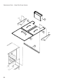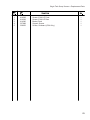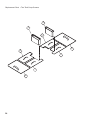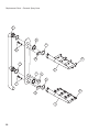
1
Installation and Service Guide with Service Replacement Parts
Beginning with Serial No. R3448 and above
E-series Rack Conveyor Dishwasher Models
Basic Single Tank
Single Tank
Model 44
Single Tank w/Prewash
Model 66 PW
Two Tank w/Prewash
Model 64
Single Tank w/Prewash
4466 PW
70 FFPW
80 HDPW
44 LT66 LTPW
70 LTFFPW
80 LTHDPW
44 DR
66 DRPW
70 DRFFPW
80 DRHDPW
44 DRWS
66 DRWSPW
70 DRWSFFPW
80 DRWSHDPW
44WS
66WSPW
70 WSFFPW
80 WSHDPW
54 DR
76 DRPW
80 DRFFPW
90 DRHDPW
Basic Two Tank
Two Tank w/ Prewash
64
86 PW
90 FFPW
100 HDPW
84
106 PW
110 FFPW
120 HDPW
Dishwasher serial no.
Issue Date: 6.12.07
www.championindustries.com
P.O. Box 4149
Winston-Salem, NC 27115
336/661-1556 Fax: 336/661-1660
Toll-free: 800.858.4477
Manual P/N 114315 rev.-
For machines beginning with S/N R3448 and above
2674 N. Service Road, Jordan Station
Ontario, Canada L0R 1S0
905/562-4195 Fax: 905/562-4618
Toll-free: 800.263.5798
For future reference, record your dishwasher information in the box below.
Model Number__________________________ Serial Number_______________________
Voltage________________Hertz_____________ Phase__________________
Champion Service Agent __________________________________ Tel:______________________
Champion Parts Distributor _________________________________ Tel:______________________
For all models:
The data plate mounts to
one side of the top-mounted
control cabinet.
National Service Department
In Canada:
Toll-free: 800/ 263-5798
Tel:
905/ 562-4195
Fax:
905/ 562-4618
email: service@moyerdiebellimited.com In the USA:
Toll-free: 800/ 858-4477
Tel:
336/ 661-1556
Fax: 336/ 661-1660
email: service@championindustries.com
ATTENTION:
We support
The dishwasher model number,
serial number, voltage, hertz and phase
are needed to identify your machine and to
answer questions.
Please have this information on-hand
if you call for service assistance.
COPYRIGHT © 2007 All rights reserved
Printed in the USA
Champion Industries, Inc.
P.O.Box 4149
Winston-Salem, NC 27115-4149
Revisions to this manual
_________________________ Revisions to this manual
•
This is where we record changes to the manual. A revision might be a part number change, new
instructions, or information that was not available at print time.
•
We reserve the right to make changes to this manual without notice and without incurring any liability
by making the changes..
•
Dishwasher owners may request a revised manual, at no charge, by calling (800.858.4477) in the
USA or (800.263.5798) in Canada.
Revision
Date
9.1.04
Revised
Pages
All
Serial Number
Effectivity
R3448 Revision Description
Released first edition 7.0608.1
Dear Owner:
Thank-you for choosing our dishwasher.
We appreciate your business.
This manual covers the E-series Rack Conveyor Dishwashers:
Electric high temperature single tank and multiple tank rack conveyor dishwashers
with built-in electric boosters in 40°F/22°C rise or optional 70°F/39°C rise.
Steam high temperature single tank and multiple tank rack conveyor dishwasher with
built-in steam booster in 40°F/22°C rise or an optional 70°F/39°C rise booster.
Electric low temperature chemical sanitizing single tank and multiple tank rack conveyor
dishwasher
The installation, and initial start-up of your dishwasher must be performed by qualified
electricians, plumbers, and authorized service technicians trained in commercial
dishwashers.
Champion provides authorized factory trained service agents to supervise the assembly
and initial start-up of your dishwasher.
Defects and repairs caused by unauthorized installers will not be covered by the
dishwasher warranty.
ii
Table of Contents
E series Rack Conveyor Dishwashers
Revisions to this manual____________________________________________________________ i
Limited Warranty__________________________________________________________________ iv
Installation ______________________________________________________ 1
Unpack and Place
Plumbing Connections
Drain Connections
Electrical Connections
Ventilation
Initial Start-up
Operating Instructions___________________________________________ 9
How to Operate your Dishwasher:
Cleaning and Maintenance
Troubleshooting
Basic Service ____________________________________________________ 19
Electrical
Mechanical
Service Replacement Parts_ ______________________________________ 33
Electrical Schematics_______________________________________ 109
iii
Limited Warranty
LIMITED WARRANTY
Champion Industries Inc. (herein referred to as Champion), P.O. Box 4149, Winston-Salem, North Carolina 27115,
and P.O. Box 301, 2674 N. Service Road, Jordan Station, Canada, L0R 1S0, warrants machines, and parts,
as set out below.
Warranty of Machines: Champion warrants all new machines of its manufacture bearing the name "Champion" and installed within the United States and Canada to be free from defects in material and workman
ship for a period of one (1) year after the date of installation or fifteen (15) months after the date of shipment by
Champion, whichever occurs first. [See below for special provisions relating to glasswashers.] The warranty
registration card must be returned to Champion within ten (10) days after installation. If warranty card is not
returned to Champion within such period, the warranty will expire after one year from the date of shipment.
Champion will not assume any responsibility for extra costs for installation in any area where there are
jurisdictional problems with local trades or unions.
If a defect in workmanship or material is found to exist within the warranty period, Champion, at its election,
will either repair or replace the defective machine or accept return of the machine for full credit; provided;
however, as to glasswashers, Champion's obligation with respect to labor associated with any repairs shall end
(a) 120 days after shipment, or (b) 90 days after installation, whichever occurs first. In the event that Champion elects to repair, the labor and work to be performed in connection with the warranty shall be done during regular working hours by a Champion authorized service technician. Defective parts become the property of Champion. Use of replacement parts not authorized by Champion will relieve Champion of all further liability in connection with its warranty. In no event will Champion's warranty obligation exceed Champion's charge for the machine. The following are not covered by Champion's warranty:
a.
b.
c.
d.
e.
f.
g.
h.
i.
j.
Lighting of gas pilots or burners.
Cleaning of gas lines.
Replacement of fuses or resetting of overload breakers.
Adjustment of thermostats.
Adjustment of clutches.
Opening or closing of utility supply valves or switching of electrical supply current.
Cleaning of valves, strainers, screens, nozzles, or spray pipes.
Performance of regular maintenance and cleaning as outlined in operator’s guide.
Damages resulting from water conditions, accidents, alterations, improper use, abuse, tampering, improper installation, or failure to follow maintenance and operation procedures.
Wear on Pulper cutter blocks, pulse vanes, and auger brush.
Examples of the defects not covered by warranty include, but are not limited to: (1) Damage to the exterior or interior finish as a result of the above, (2) Use with utility service other than that designated on the rating plate, (3) Improper connection to utility service, (4) Inadequate or excessive water pressure, (5) Corrosion from
chemicals dispensed in excess of recommended concentrations, (6) Failure of electrical components due to
connection of chemical dispensing equipment installed by others, (7) Leaks or damage resulting from such
leaks caused by the installer, including those at machine table connections or by connection of chemical
dispensing equipment installed by others, (8) Failure to comply with local building codes, (9) Damage
caused by labor dispute.
Warranty of Parts: Champion warrants all new machine parts produced or authorized by Champion to be free from defects in material and workmanship for a period of 90 days from date of invoice. If any defect in
material and workmanship is found to exist within the warranty period Champion will replace the defective
part without charge.
DISCLAIMER OF WARRANTIES AND LIMITATIONS OF LIABILITY. CHAMPION'S WARRANTY IS ONLY TO THE EXTENT REFLECTED ABOVE. CHAMPION MAKES NO OTHER WARRANTIES, EXPRESS OR IMPLIED, INCLUDING,
BUT NOT LIMITED, TO ANY WARRANTY OF MERCHANTABILITY, OR FITNESS OF PURPOSE. CHAMPION SHALL
NOT BE LIABLE FOR INCIDENTAL OR CONSEQUENTIAL DAMAGES. THE REMEDIES SET OUT ABOVE ARE
THE EXCLUSIVE REMEDIES FOR ANY DEFECTS FOUND TO EXIST IN CHAMPION DISHWASHING MACHINES AND
CHAMPION PARTS, AND ALL OTHER REMEDIES ARE EXCLUDED, INCLUDING ANY LIABILITY FOR INCIDENTALS
OR CONSEQUENTIAL DAMAGES.
Champion does not authorize any other person, including persons who deal in Champion dishwashing machines
to change this warranty or create any other obligation in connection with Champion Dishwashing Machines.
iv
Model Descriptions
Model Descriptions
Champion single tank and two tank rack conveyor dishwashers are fully automatic.
Standard equipment includes 1HP prewash, 2HP wash and 2HP power rinse
pumps. The conveyor drive is a 1/6 HP motor. All models are available in
right-to-left (R-L) or left-to-right (L-R) direction.
Model Numbers
Single Tank - Basic........................................... 44, 54, 44 WS, 44 LT
Single Tank with 22" Prewash........................... 66 PW, 76 PW, 66 WS, 66 LT PW
Single Tank with 36" Prewash........................... 80 HDPW, 90 HDPW, 80WS HDPW
Single Tank with 26" Front Feed Prewash........ 70 FFPW,80 FFPW, 70 WS FFPW
•
•
•
The 44 DR and 54 DR basic models are high temperature 180°F/80°C hot final rinse
water sanitizing dishwashers. Prewash options are available in 22", 36", and
26" front feed. Built-in stainless steel electric booster heaters in 40°F/22°C and
70°F/39°C rise are available and steam booster heaters in 40°F/22°C and 70°F/39°C
rise. Dual-Rinse (DR) models feature a recirculating rinse that conserves energy.
The 44 WS and 44 DRWS models are WaterSaver high temperature 180°F/80°C
hot final rinse water sanitizing dishwashers. Prewash options are available in 22",
36", and 26" front feed. Built-in stainless steel electric booster heaters in 40°F/22°C
and 70°F/39°C rise are available and steam booster heaters in 40°F/22°C and 70°F/39°C rise. Dual-Rinse (DR) models feature a recirculating rinse that conserves energy.
The 44 LT and 66 LT models are low temperature 140°F/60°C sodium hypochlorite (chlorine bleach) sanitizing final rinse to maintain a minimum concentration of
50 PPM on the wares. The concentration of sanitizer must be tested at regular
intervals using chlorine test papers.
Two Tank - Basic.................................................64, 72, 84
Two Tank with 22" Prewash................................86 PW, 94 PW, 106 PW
Two Tank with 36" Prewash................................100 HDPW, 108 HDPW, 120 HDPW
Two Tank with 26" Front Feed Prewash..............90 FFPW, 98 FFPW, 110 FFPW
•The 64, and 84 basic models are high temperature 180°F/80°C hot water final rinse sanitizing models. Prewash options are available in 22", 36", and 26" front feed.
Built-in stainless steel electric booster heaters in 40°F/22°C and 70°F/39°C rise are
available and steam booster heaters in 40°F/22°C and 70°F/39°C rise.
•All rack conveyor dishwasher models are covered by a 1-year parts and labor limited
warranty.
1
Blank Page
This Page
Intentionally
Left Blank
2
Installation
Installation
Unpack and Place
!!ATTENTION!!
Use caution when moving or lifting the dishwasher to prevent
damaging the dishwasher or the installation site.
Check doorway and passageway clearance before moving
the dishwasher.
Remove dishwasher front panels and check under the
machine base for obstructions before moving.
1. Inspect the dishwasher for shipping damage and immediately report any damage to the
freight carrier. Save all packing materials.
2. Check the dishwasher interior for curtains, panels and other supplies.
3. Lift the dishwasher off the shipping pallet and move the machine to its permanent location.
4. Leave a minimum of 6" between walls and the rear of the dishwasher.
5. Level the dishwasher side-to-side and front-to-back using a bubble level.
The dishwasher legs are adjusted by screwing them in or out.
6. Do not remove tags attached to the utility connections.
7. Remove the protective film from the dishwasher exterior.
Remove any foreign material from the dishwasher interior.
Plumbing - Hot water supply
NOTE:
Only qualified personnel should make dishwasher plumbing connections.
Connections must meet local plumbing and sanitary codes.
Improper installation is not covered by the dishwasher limited warranty.
1. Connect a 3/4" NPT hot water supply line to the line strainer located at the top rear of the
dishwasher.
For a dishwasher without a booster heater, the hot water connection must supply a
minimum of 180ºF/80ºC (measured at the dishwasher).
For a 40ºF/22ºC rise booster heater, the hot water connection must supply a minimum of
140ºF/60ºC (measured at the dishwasher).
For a 70ºF/39ºC rise booster heater, the hot water connection must supply a minimum of
110ºF/45ºC (measured at the dishwasher).
For a low temperature chemical sanitizing machine, the hot water connection must supply
a minimum of 140ºF/60ºC (measured at the dishwasher).
2. Install a pressure reducing valve (PRV) before the dishwasher supply connection if the
flowing line pressure is greater than 25psi [173kPa] at the machine. Set the PRV flowing
pressure to 20-22psi [138-151 kPa]. PRV's are supplied by Champion or others.
3
Installation
Installation
Plumbing Connections - Hot water supply continued
3. Install service shut-off valves in the supply line as close to the dishwasher as possible.
Valves must be the same size or larger than the supply line.
Cold water supply
1. Connect a 1/2" NPT cold water supply line for dishwashers equipped with a prewash cold
water tempering option. Connection is located at the top rear of the dishwasher load end.
2. Connect a 1/2" NPT cold water supply line for dishwashers equipped with a drain cold water
tempering option. Connection location can vary depending on site requirements.
Drain Connections
1. The drain trunk line was removed and packed inside the dishwasher prior to shipping.
Install the drain trunk line. Dual-Rinse (DR) models also have PVC drain lines that were
packed inside the dishwasher. Install the PVC piping on the unload end of the dishwasher.
2. Connect a 1-1/2" NPT or larger gravity drain line to the dishwasher. Observe local
plumbing and sanitary codes.
Steam Supply and Condensate Connections
1. Connect a steam supply line the same size or larger to the dishwasher at the steam
supply strainer located at the steam booster heater.
2. Connect a gravity condensate return line to the dishwasher. A condensate drain water
lift pump (supplied by others) must be installed if the condensate return line rises
above the finished floor (AFF).
Ventilation
DO NOT VENT the dishWasheR into WaLLs, ceiLinGs, oR conceaLed spaces.
1. Connect stainless steel water-tight duct INSIDE the 4” x 16” [102mm x 407mm]
vent stacks at the load and unload ends of the dishwasher.
2. A minimum of 6 air changes per hour of kitchen air is recommended.
3. Follow the ventilation requirements below.
Dishwasher with prewash tank
Load end -150 CFM @ 1/4” (SP), [71 Liters/Sec]
Unload end - 400 CFM @ 1/4” (SP), [189 Liters/Sec]
Dishwasher without prewash tank
Load end -200 CFM @ 1/4” (SP), [95 Liters/Sec]
Unload end - 400 CFM @ 1/4” (SP), [189 Liters/Sec]
4.Dishwasher vents are equipped with adjustable dampers.
4
Installation
Installation
Electrical Connections
WARNING !
ELECTRIC SHOCK may cause INJURY OR
DEATH.
This dishwasher may have multiple
power service connections.
Do not work on any energized circuit.
Turn off all main power service disconnect switches.
Attach a label to the breaker indicating that work is being
done on the electric circuits.
!!ATTENTION!!
Electrical and grounding connections
must comply with the
National Electrical Code and
Local Electrical Codes.
A qualified electrician must compare the
electrical power supply with the machine
electrical specifications stamped on the
MACHINE ELECTRICAL
CONNECTION PLATE
located inside the control cabinet before
connecting the main power to the dishwasher.
MACHINE ELECTRICAL CONNECTION
1. The Main incoming power to the dishwasher is made at the top of machine in
the control cabinet.
2. The electrician must connect the incoming power based on the information
that is stamped on the Machine Electrical Connection Plate.
3. Any change to the Machine Electrical Connection Plate must be approved
by the factory in advance.
4. The dishwasher main power terminal block is located inside the top-mounted
control cabinet.
5. A knock-out plug is provided at the rear of the control cabinet for electrical
service connections.
6. Built-in electric booster heaters have a separate main power connection
except Models 44 WS and 66WS.
7. Electric blower-dryers have a separate main power connection.
5
Installation
Electrical Connections continued
8. Motor rotation was set at the factory.
9. The conveyor drive motor rotation is indicated by a red arrow located on the side of the motor.
10. The single phase drive motor (208-240V only) rotation must be changed at the drive motor junction box.
11. Three phase drive motor (480-575V) rotation must be reversed in the control cabinet.
12. Reverse the L1 and L2 wires on the output side of the dishwasher Main Terminal Block (MTB) located inside the top-mounted control cabinet.
The photograph to the right shows
the conveyor drive motor with its
direction arrow.
A wash pump/motor assembly can be
seen in the background.
6
Installation
Chemical Connections
1. Use a qualified detergent/chemical supplier for
detergent/chemical and dispensing equipment needs.
2. Labeled detergent control circuit connection terminals
are provided in the control cabinet for detergent and
rinse agent/sanitizer dispensing equipment (supplied by
others).
3. The illustration on the right, shows the terminal board
for the current production machines .
The signal connection points include:
• Detergent signal 120VAC, 1Amp max amp load
• Rinse aid/Sanitizer signal 120VAC, 1Amp max amp
load
4. A removable black plug is provided in the load end side of the wash
tank (behind the drive motor) for installation of the detergent
conductivity cell.
Curtain Locations
1. Refer to the illustrations below and hang the curtains as shown.
J-hooks are located in the corners of each section to accept the curtain rods.
•
•
Standard long curtains
High hood long curtains
24” x 20-1/4”
24” x 22-3/4”
•
•
•
Standard short curtains
High hood short curtains
Final rinse curtain
24” x 13-/14”
24” x 20-1/4”
24” x 6-1/4”
2. Make sure the that the short flaps of the curtains face the load end of the dishwasher. The
longest curtains always go on each end of the dishwasher.
7
Installation
Attach the dishtables
1. Attach dishtables (supplied by others) to the load and unload ends of the dishwasher.
2. The table must fit over the dishwasher end flange and extend down into the
dishwasher.
3. The dishtables must angle toward the dishwasher so water on the tables will drain
into the dishwasher. The dishtables should have adjustable feet to adjust the angles.
4. Use a food grade silicon sealant to seal the joints between the dishtables and the
dishwasher.
Install a table-limit switch
A table-limit switch prevents damage to the dishwasher conveyor drive if dishracks pile up
on the unload dishtable and jam the conveyor.
A taBLe-Limit sWitch instaLLation Kit, P/N 407400 with installation instructions
is available from Champion.
!!ATTENTION!!
Damage to the dishwasher conveyor drive can happen
when dishracks jam together on the unload dishtable.
Champion strongly recommends
the installation of a table-limit switch to prevent
dishrack jams at the unload of the dishwasher.
Final Installation Checks
1. Remove any foreign material from inside of the machine.
2. Check dishwasher drain/overflows are closed
3. Install scrap screens and baskets
4. Turn utilities on.
5. Turn dishwasher on to fill tanks with water.
6. Check tank water temperatures reach proper levels.
7. Check for leaks.
8. Drain the dishwasher and check that floor drains handle the
water volume leaving the dishwasher.
8
Operation
Operation
IMPORTANT
Please read the steps below before you operate your dishwasher.
1.
Make sure the dishwasher was properly installed and tested prior to operation.
2.
Read the operating instructions completely before you operate your dishwasher for
the first time.
3.
Keep these instructions available for quick reference.
4.
Contact your supervisor immediately if you have questions about the dishwasher.
5.
Contact your local authorized Champion service agency for technical support.
6.
Our National Service Department provides 24 hour support 365 days a year with a
Toll-free number in the United States.
USA National Service
M-F • 8 AM - 5PM EST
Toll-free: 1 (800) 858-44772
In the USA, a factory technician will return your call after-hours and during holidays.
or
Canadian National Service
M-F • 8:30 AM - 4:30PM EST
Toll-free: 1 (800) 263-5798
9
Operation
Operation
Follow the procedure below to operate your dishwasher properly.
1. Check that the spray pipes, curtains, and scrap screens are in place and clean.
2. Check that the overflow drains are closed.
3. Turn on the detergent dispenser switches and check the detergent supply.
4. Turn on the exhaust vent system (if applicable), and make sure it is operating.
5. Close the door(s). Push the power switch ON, light will illuminate.
Machine will begin to fill via the fill valve and the final rinse piping.
6. When the tanks are full, wait until the wash tank has reached the proper temperature.
Check the wash tank temperature gauges located on the control cabinet. Minimum
wash temperatures are:
•
44 LT, 66 LT PW -140°F/60°C
•
44, 54, 44 WS - 160°F/71°C
•
66 PW, 76 PW, 66 WS PW - 160°F/71°C
7. Push the Green start button. The pushbutton illuminates indicating the dishwasher
is ready for automatic operation.
8. Pre-scrap wares to remove large food particles and load wares into the dishracks.
DO NOT OVERLOAD RACKS.
9. Pegged racks are for plates and/or trays. Flat racks are for bowls and/or silverware.
Spread silverware evenly in a single layer in a flat rack or upright (loosely packed) in
a cutlery rack/cylinder.
9. Push a dishrack into the load-end of the dishwasher until it contacts the idle pump
switch lever; the conveyor and pumps will start.
The dishwasher will run for 90 seconds to wash, rinse and move the dishrack out
of the unload-end of the dishwasher.
10.Inserting another dishrack into the machine before the first rack exits will keep the
dishwasher running until the last dishrack exits the machine.
10.Check the final rinse pressure and temperature as the racks pass through the final
rinse. This final rinse pressure MUST be 20-22 psi [138-151 kPa] and the final rinse
temperature MUST be a minimum of 180°F/82°C .
11. The pumps and the conveyor drive will automatically stop after the last rack exits
the machine.
12. The machine may be stopped at any time during the cycle by pressing the red STOP
pushbutton. The green light will go off on the green START pushbutton.
13.Check the interior of the dishwasher for any dishracks still in the machine.
These dishracks must be washed again to ensure they are washed and sanitized
completely.
14.To restart, push the green START pushbutton and push another dishrack into the
dishwasher load-end until the pumps and conveyor start again.
15.Repeat steps 7-10 until all wares are washed.
10
Operation
Operation
Door Safety Switches
Dishwasher access doors are equipped with a door safety switch that automatically
stops the dishwasher pumps and conveyor drive if a door is raised while the dishwasher
is running. In addition, the diswasher will not start if a door is left open.
1. If the dishwasher is running and a door is raised, then lighted GREEN START pushbutton goes out and the pumps and conveyor drive stop.
2. Check the interior of the dishwasher for any dishracks still in the machine.
These dishracks must be washed again to ensure they are washed and sanitized
completely.
3. To restart the dishwasher, make sure all doors are closed, then push the GREEN
START pushbutton.
4. Insert a dishrack into the dishwasher until the pumps and conveyor run.
Sprayarms and Scrap Screens
The illustrations below and on the proceeding pages illustrate how to install and
remove the sprayarm assemblies and scrap screens.
Removing the lower sprayarm assembly
11
Operation
Removing the sprayarm end plugs for Cleaning
Installing the lower sprayarm
assembly
12
Operation
Installing the upper sprayarm assembly
Removing the sprayarm end plugs for cleaning
13
Operation
Removing the Dual Rinse (DR) scrap screens
1
2
14
Operation
Removing the Dual Rinse (DR) scrap screens (continued)
15
Maintenance
Maintenance
Cleaning your dishwasher is the best maintenance you can do.
The cleaning intervals below are the minimum requirements for most dishwashers.
You may need to clean your dishwasher more often when washing heavily soiled wares
or during long hours of continuous operation.
Cleaning
Cleaning Intervals
• Daily or every 2 hours of operation
1.
2.
Turn power switch to OFF.
Pull drain lever(s) to drain water. Remove scrap screens and scrap baskets.
Clean inside of the tanks and flush with clean water.
Back flush the scrap screens until clean.
DO NOT stRiKe scReens oR BasKets aGainst soLid oBJects
3.
Remove the sprayarm assemblies. Remove the end cap from each sprayarm.
Flush the sprayarms and nozzles to remove any debris.
Replace the end caps. Check the condition of the manifold O-ring.
Reinstall the sprayarms.
4. Remove and clean the curtains. Allow them to dry at the end of the day.
5. Leave the doors open between operations, allowing the machine to dry.
6. Make sure that the final rinse nozzles are clear of mineral deposits.
Straighten a metal paper clip to clean the nozzles. 7. Check the temperature and pressure gauge readings during operation.
8. Inspect the machine for signs of water leaks.
9. Check the chemical supplies and refill as necessary.
10. Report unusual conditions to your supervisor.
16
Maintenance
Cleaning
• Weekly
1. Inspect all water lines for leaks and tighten at joints if required.
2. Clean any detergent residue from the exterior of the machine.
3. Check that the drain/overflow pipes seat tightly in their drains.
4. Clean any accumulated scale from the heating element.
5. Inspect the sprayarms for any damage or missing parts.
6. Inspect the final rinse arms for missing parts.
7. Inspect the pawl bar and drive assembly for damage or missing parts.
8. Check that float switches move freely.
9. Check the idle pump actuator and the final rinse actuator for freedom of
travel.
Deliming
The word SCALE
refers to the mineral deposits that form as a white film inside and
sometimes outside the dishwasher. If allowed to build-up, scale can significantly
reduce the performance and life-span of a dishwasher.
Scale must be removed using strong chemicals (deliming agents) that are supplied
by a qualified chemical supplier. Your supplier will explain the safety procedures you
must follow to prevent personal injury and possible damage to the dishwasher.
Deliming agents vary in compostion and strength so it is impossible for Champion
to provide detailed instructions for the large number of products on the market;
therefore, Champion strongly recommends that you do not use any deliming
agent without the proper training.
WARNING:
Death or injury can result from toxic fume when deliming agents
come in contact with Chlorine Bleach, or other chemicals that contain
iodine, bromine, or flourine. clothing as instructed by a qualified
chemical supplier.
USE EXTREME CAUTION WHEN HANDLING ANY DELIMING AGENT
CAUTION:
Deliming agents can cause chemical burns.
Wear rubber gloves, eye protection and any other protective
clothing as instructed by a qualified chemical supplier.
17
Blank Page
This Page
Intentionally
Left Blank
18
Basic Service
Basic Service
19
Electrical • Basic Service
Electrical Service
Fuse Blocks - 120VAC Control Voltage
Two fuse blocks, located in the center of the front of the main control cabinet
protect the main control transformer. Each fuse block holds one fuse.
Always replace a blown fuse with a fuse of the same AMP rating.
DO NOT INCREASE THE FUSE RATING.
Motor Overloads
Motor overloads are located to the left of the fuse block inside the control cabinet. Each
motor has one overload to protect it from line voltage electrical overloads. In addition,
an auxiliary set of switch contacts is attaches to the overload. The switch contacts
disconnect 120VAC power to the motor contactor coils in the event of an overload
condition.
A motor Overload has 2 rocker switches, OFF/STOP and ON/START.
• The motor overload has tripped if the Off/Stop switch is in the Off position.
Set the rocker switch to STOP. Then, push the ON/START rocker switch to the ON position
• The motor overload rocker switch
is in the START position when the
pump is ON and in the STOP position
when the motor is OFF.
• Turn the dishwaser power ON and
insert a dishrack to start the pumps
and conveyor. Troubleshoot the motor circuit. The motor overload
may be faulty if motors are OK.
•
Arrows indicate the Full load Amp
(FLA) adjustment screws. Each
screw should be set to the FLA
rating found on the motor the data plate.
Pump/Conveyor Run Timer
The solid-state pump/conveyor run timer is a fixed 90-second timer
that controls the maximum time that the pumps and conveyor drive
motor runs after a dishrack enters the load-end of the dishwasher.
90-seconds is the time necessary for 1 dishrack to complete its
travel through the dishwasher ensuring that wares are washed
and rinsed before exiting the machine.
The timer resets to 90-seconds each time a dishrack enters the
dishwasher. This ensures that every dishrack is processed
completely.
A faulty pump/conveyor run timer is possible if the 90-second run
time is off by plus or minus 2-seconds. The idle-pump start switch located on the loadend dishwasher should be checked for proper operation before replacing the timer.
20
Basic Service • Electrical
Electrical Service (continued)
Pump/Conveyor Timer
Timer Sequence of Operation:
•
•
•
•
•
A dishrack entering the machine contacts the idle pump switch lever.
The contacts of the idle pump switch open, de-energizing control relay 1CR.
Normally closed contacts of 1CR close and apply a signal to pump timer. The timer
contacts close turning on the pump(s) and drive motor
The dishrack moves off the idle pump switch lever and the switch contacts close.
1CR energizes and the notmally closed contacts open removing the signal from the
pump timer.
• The pump timer begins to time down for its 90 seconds time setting.
• The timer is reset each time the idle pump switch is activated. If the timer is reset only once it will time out and shut the pump(s) and drive motor off after the time delay.
To Check the Pump Timer Setting:• Turn the power on.
• Press the green lighted START pushbutton.
• Place a rack in to the conveyor.
• When the rack enters the load end, the pump(s) and the drive motor will start.
• Time the conveyor and when the rack clears the idle pump switch.
Note the elapsed time when the machine stops. The elapsed time should be within 2-seconds of the timers 90-second setting.the timer.
• Replace the timer if the is off more than 2-seconds.
21
Electrical • Basic Service
Electrical Service (continued)
Automatic Fill/Low Water Heat Protection
Dual Float Switches
Each tank contains a dual float switch.
The part consists of an angled stem containing two reed
switches. Two stainless steel ball floats, containing magnets,
slide over the stem and are free to move up and down. When
the float moves on the stem, it opens and closes the
associated reed switch inside the stem. The reed switches
control relays. The relays control the automatic fill and heat for
different parts of the machine. The float switch(es) and their
relay(s) operate on a 120VAC circuit.
Operation Sequence
Bottom Float and Reed Switch
• The bottom float controls the heat.
• When the bottom float is down, the bottom reed switch contacts are open.
• When the bottom float is up, the bottom reed switch contacts are closed.
Top Float and Reed Switch
• The top float controls a fill valve, which controls the water level.
• When the top float is down, the top reed switch contacts are open.
• When the top float is up, the top reed switch contacts are closed.
Initial Fill
• When the tank is empty, both floats are down and their reed switch
contacts are open.
• The control relay for the float switch is de-energized.
• The fill valve for the tank is energized and the tank begins to fill with water.
• As the water level in the tank rises, the bottom float begins to move up.
• When the bottom float is completely up, its reed switch contacts close.
• This prepares the heat circuit, but the heat DOES NOT energize at this time.
• The tank continues to fill until the top float is completely up.
• The top float’s reed switch contacts close. Its control relay energizes.
• The fill valve de-energizes.
• The heat circuit energizes through the contacts of the control relay.
22
Basic Service • Electrical
Automatic Fill/Low Water Heat Protection
Dual Float Switches (continued)
During Normal Operation
• If the water level in a tank falls below the level of the top float, the top float moves
down and its reed switch contacts open.
• When the water level falls below the level of the bottom float, the bottom float moves down and its reed switch opens.
• The control relay de-energizes. The fill and rinse valve energizes and refills the tank.
• The heat circuit will de-energize until the water level in the tank raises the top float again.
• The bottom float keeps the heat circuit ready as long as the water level is above the level of the bottom float.
Electric Tank Heat Control and High-limit Thermostats
Two thermostats regulate the temperature for wash tanks, final rinse boosters,
and dual rinse electric heaters.
Control thermostats are adjustable from 110ºF to 195ºF.
Turn the thermostat adjusting screw CW to increase the temperature or
CCW to decrease the temperature.
High-limit thermostats are not adjustable. They prevent the electric heaters
from overheating in the event that a control thermostat or some other component
fails.
Wash tank control and high-limit thermostats are located in junction boxes mounted to
the front of the wash tank.
Electric booster control and high-limit
thermostats are located on the base of the
dishwasher adjacent to the booster heaters.
Dual rinse tank control thermostats are
located on the front of the unload-end of the
dishwasher. The high-limit thermostat is a
surface thermostat and is mounted on
the end of the dual-rinse tank.
23
Electrical • Basic Service
Multi-Voltage Pump Motors:
Low voltage: 208-230VAC
High voltage:460VAC or 575VAC
Motor Connections:
Low voltage
208-230V/1PH
High voltage
460V/3PH
Low voltage
208-230V/3PH
575V/3PH
Only
Troubleshooting
Motor will not run
1. Check incoming power to control cabinet.
2. Check for tripped manual motor starter (overload) in control cabinet.
(Refer to Motor Overload service section for proper settings).
3. Check power at motor contactor.
Motor runs hot and trips motor starter overload
1. Check for proper voltage between L1-L2 or (L1-l2, L2-L3, L1-L3 for 3 phase).
2. Check FLA on motor leads L1, L2, (also L3 for 3 phase) using amp tester.
(Motor full load amp (FLA) ratings are stamped on motor nameplate).
Motor Replacement
1. Disconnect the power to the machine.
2. Disconnect the wires to the motor junction box.
3. Make note of the motor connections in order to phase the replacement correctly.
4. Install the new motor and check for proper rotation.
(Proper rotation is clockwise looking from at the rear of the motor).
5. Motor rotation can be reversed by switching L1 and L2 on three phase motors.
Single phase motor rotation cannot be reversed.
24
Basic Service • Electrical
Motors-Drive
Voltage:
Standard motors are multi-voltage
Low Voltage:
208-240VAC
High Voltage:
380/480/575VAC
1 Phase Only
3 Phase Only
208-240V 1Phase Wiring Diagram
To reverse motor rotation interchange yellow and orange leads.
Motor 1/6 HP
208/240V
White Wire
Run
Winding
Orange Wire
Capacitor
10MFD
370VAC
Start
Winding
Yellow WIre
Brown Wire
Black Wire
Connect 208/240V
Power Here
Run X
Winding
Red Wire
380/480/575/V 3Phase Wiring Diagram
To reverse motor rotation interchange any two external connections.
Motor 1/6HP
380/480/575 Volt
P6 Orange Wire
P5 Tan Wire
P4 Blue Wire
T6 Purple Wire
T9 Brown Wire
T4 Yellow Wire
T7 Pink Wire
T5 Black Wire
T8 Red Wire
T3 Orange Wire
T1 Blue Wire
T2 Tan Wire
Connect 380/480/575V
3 Phase
Power Here
Conveyor Drive Jam Switch • The conveyor jam switch stops the conveyor if something obstructs the movement of
of the rack conveyor.
• The light on the green start switch goes out and the pumps and the conveyor drive
motor stop running.
• After clearing the jam, push the green start button and insert another dishrack to restart the pumps and conveyor. Be sure to wash any dishracks that may have been
stalled in the dishwasher prior to the jam condition.
25
Mechanical • Basic Service
Mechanical Service • Pump Seal Replacement
NOTE !
Study the instructions below
before you replace a pump seal.
Remove Defective Pump Seal
1.
Disconnect the power to the machine.
2.
Disconnect the wires at the motor junction box.
3.
Make note of the motor connections in order to phase the replacement correctly.
4.
Remove pump/motor assembly to a clean work area.
5.
Follow the diagrams below for pump disassembly and seal replacement.
Mark alignment of motor and pump
Remove pump volute.
continued on next page
26
Basic Service • Mechanical
Mechanical Service • Pump Seal Replacement
3
2
1
continued on next page
27
Mechanical • Basic Service
Mechanical Service • Pump Seal Replacement
NOTE !
Replace the pump motor if motor shaft is grooved, pitted, or bent.
Clean rust and debris from seal seat and motor shaft. Debur with fine
finishing paper specifically designed for metal surfaces.
Use a new seal assembly preferably from an unopened package.
The wax paper, and paper disk between the seal parts should be intact.
Avoid touching the graphite or the ceramic surfaces of the seal assembly.
Check both surfaces for cracks, chips, oil or grease. Discard the seal and
get a new one if any damage is found.
Install New Pump Seal
DO NOT TOUCH CERAMIC
Impeller and pump housing do not touch DO NOT TOUCH GRAPHITE
Turn impeller CCW. Properly installed
pump seal prevents freewheeling.
continued on next page
28
Basic Service • Mechanical
Mechanical Service • Pump Seal Replacement
.032”
.015”
.0085”
3
2
1
Use Champion OEM Shim/Gasket Kits Only: P/N 900737
Number and thickness of shims will vary between pumps.
Notches in a shim identifies thickness.
Measure gap between impeller vanes and pump volute.
Minimum clearance must be .030” [0.76 mm].
Rotate the motor shaft CW to check proper
clearance. Reinstall assembly and test run
checking for leaks. Look at the rear of the motor
to make sure motor shaft rotation is CW.
continued on next page
29
Mechanical • Basic Service
Mechanical Service • Replace Electric Booster Control Thermostat
WARNING !
ELECTRIC SHOCK may cause INJURY OR
DEATH.
Do not work on an energized circuit.
Turn off the main power service disconnect switch.
Attach a label to the breaker indicating that work is being
made on the electrical circuit.
NOTE !
READ ALL OF THE THERMOSTAT INSTRUCTIONS
BEFORE YOU REPLACE THE CONTROL THERMOSTAT
USED IN AN ELECTRIC BOOSTER HEATER.
IMPROPER INSTALLATION CAN CAUSE FINAL RINSE
TEMPERATURE PROBLEMS.
1.
You will need a permanent marker such as a SHARPIE® or comparable in order
to mark the control thermostat capillary tube.
2.
Do not crimp the thermostat capillary tube.
3. The ferrule cannot be repositioned after the gland nut has compressed the ferrule
on the capillary tube.
4.
30
The control thermostat fitting is located on the left underside of the booster tank
when viewing the booster tank from the front.
Basic Service • Mechanical
Mechanical Service • Replace Electric Booster Control Thermostat
Slide ferrule 8” away from the end of the thermostat probe and mark.
Thread gland nut into booster tank fitting.
1"
Insert thermostat probe into
booster tank taking care not
to crimp capillary tube.
8"
Slide ferrule and small gland nut
up to mark on capillary tube.
Tighten small gland nut to seal
the assembly.
Complete the installation of
the thermostat body and check
booster heater operation.
31
Blank Page
This Page
Intentionally
Left Blank
32
Replacement Parts
_________________Replacement Parts
33
Replacement Parts • Prewash Doors & Panels
10
6
9
7
12
8
8
11
11
12
5
12
4
3
12
12
2
34
1
Prewash Panels & Doors • Replacement Parts
1
397970
Panel Assy. Front Perimeter 22" PW Prewash
1
---
328978
Panel Assy. Front Perimeter 36" Prewash
1
2
327857
Panel, 25" Prewash Perimeter
1
3
328030
Table Flange Support
1
4
329926
Baffle, Table Flange
5
328006
Support, 22" PW Rear Screen
1
6
108250
Rod Curtain 5/16 x 24-5/8"
1
7
108043
Curtain 24 x 13-1/4"
1
8
113691
Guide, U-channel Door
2
9
113486
Screw 8-32 x 5/8" Flat Hd SST
12
10
327952
Door, 22" Prewash
1
---
111026
Magnet, Door (Not Shown)
1
---
113719
Switch, Reed Aleph (Not Shown)
1
11
108966
Door Handle
2
12
100073
Screw1/4-20 x 1/2 Truss Head
2
35
Replacement Parts • Single Tank Doors & Panels
9
11
8
7
5
6
10
11
3
4
11
2
12
1
36
Single Tank Doors & Panels • Replacement Parts
1
328974
Panel Assy., 44 Front Perimeter
1
2
327889
Panel, 25” Side Perimeter (Load, L-R, No PreWash)
1
3
327889
Panel, 25” Side Perimeter (Unload, L-R No Booster)
1
4
329926
Baffle
5
327857
Door
1
---
111026
Magnet, Door (Not Shown)
1
---
113719
Switch, Reed Aleph (Not Shown)
1
6
108966
Door Handle
1
7
113691
Guide, U-channel Door
2
8
113486
Screw, 8-32 x 5/8 Flat Head SST
12
9
108250
Rod, Curtain 5/16 x 24-5/8
3
10
113720
Curtain 24 x 20-1/4 4 Ply (Load and Unload)
2
---
109723
Curtain 24 x 6 -1/4 (Not shown)
1
11
100007
Screw 1/4-20 x 1/2 Truss Head SST
6
12
100734
Bolt 1/4-20 x 1/2 SST
3
1
37
Replacement Parts • Two Tank Doors & Panels
1
2
3
13
10
4
4
5
9
3
4
9
14
10
11
6
10
12
5
7
3
8
38
Two Tank Doors & Panels • Replacement Parts
1
414303
Door Assembly Includes Items 2-3
2
---
327851
Door without handle
2
---
111026
Magnet, Door (Not Shown)
1
---
113719
Switch, Reed Aleph (Not Shown)
1
2
108966
Door Handle
2
3
100073
Screw 1/4-20 x 1/2 Truss Head
8
4
113691
Guide, U-channel Door
4
5
327889
Panel, 25” Side Perimeter (Load, No Prewash)
1
---
327889
Panel, 25” Side Perimeter (Unload, No Booster)
1
6
328975
Panel, 64 Front Perimeter
1
7
328976-01
Panel, 84 Front Perimeter Right Hand
1
8
328976
Panel, 84 Front Perimeter Left Hand
1
9
113720
Curtain 24 x 20” (Load/Unload)
2
10
108250
Rod, Curtain 5/16 x 24-5/8”
4
11
108043
Curtain 24 x 13-1/4” (Wash/Rinse)
1
---
109723
Curtain 24 x 6-1/4” (Rinse/Final Rinse)(Not Shown)
1
12
328030
Table Flange
2
13
113486
Screw 8-32 x 5/8 Flat Head SST
12
14
329926
Baffle
1
39
Replacement Parts • Drive Motor Assembly
3
1
15
16
2
4
13
5
13
17
8
11
11
12
9
7
6
8
10
14
40
Drive Motor Assembly • Replacement Parts
1
0509199
Drive Motor Switch
1
2
327918
Bracket, Motor Switch Mounting
1
3
103166
Sheave AK 39 5/8 Bore (44)
1
3
113893
Sheave AK 51 5/8 Bore (64)
1
4
327916
Plate, Drive Motor Mounting
1
5
327920
Plate, 44 Motor Assy Mounting
1
5
327917
Plate, 64 Motor Assy Mounting
1
6
327919
Bracket, Motor Spring Mounting
1
7
100154
Hex Nut Plain 5/16-18 SST
2
8
102376
Washer, Flat 5/16 x 3/4 x .06 SST
4
9
113702
Spring 0.6OD x 0.095 Wire x 1.5 Lg
1
10
113704
Screw, 5/16 x 3-1/2 Hex Head SST
1
11
113700
Bushing 3/8 x 3/4 x 1/16 Thrust Bronze
3
12
113703
Bushing, 3/4 x 7/8 x 3/8 x 1-1/8 Flg
1
13
113701
Bushing 1/4 x 3/8 x 1/2 x 1/16 Flg Bronze
1
14
113732
Motor, Gear 1/6HP 3PH
1
14
113679
Motor, Gear 1/6HP 1PH
1
15
100734
Bolt 1/4-20 x 1/2 Hex Head SST
2
---
106482
Washer Lock 1/4 Split
2
16
100736
Bolt 1/4-20 x 3/4 Hex Head
3
---
106482
Washer Lock 1/4 Split
3
17
100734
Bolt 1/4-20 x 1/2 Hex Head SST
2
---
106482
Washer Lock 1/4 Split
2
41
Replacement Parts • Drive Assembly
10
11
1
2
3
12
4
13
5
6
7
8
18
9
14
15
19
16
20
17
42
Drive Assembly • Replacement Parts
1
2
3
4
5
6
7
8
9
10
11
12
13
14
15
16
17
18
19
----20
-------
202381
100868
107089
206300
206301
206302
102244
206303
100382
100007
104925
103180
104916
100794
113892
327924
113860
104923
100153
104618
109010
100739
100154
106013
109009
Roller Crosshead
Roller Stud Crosshead
Nut Jam 1/2-13
Crank, Rack Arm
Shaft 5/8 Diameter 8-3/8 LG
Housing, Bearing/Seal
Seal 5/8”
Gasket/Bearing Seal
Bearing Jaf #EK104-10
Screw, 10-32 x 3/8 Truss Head
Washer 1/4 x 1 x 16 Gauge
Wiper Ring
Key 3/16 x 3/16 x 3/4 SST
V-belt 4L 310
Sheave AK 59-5/8 Bore
Bracket, 44 Drive Bearing Mounting
Bearing, Sealed 5/8 Bore
Screw 1/4-20 x 3/8 Round Head
Bolt 3/8-16 x 1 Hex Head
Washer 3/8 x 7/8 x 1/16 SST
Nut Grip 3/8 w/Nylon Insert
Bolt 5/16-18 x 3/4 Hex Head SST
Nut Plain 5/16-18
Washer Lock 5/16 Split
Nut Grip 5/16 w/Nylon Insert
1
1
1
1
1
1
1
1
1
1
1
1
1
1
1
1
1
4
4
4
4
2
2
2
2
43
Replacement Parts • Prewash Track & Cradle Assembly
17
14
12
11
13
19
10
8
7
4
9
6
2
15
3
18
16
Tank
20
5
44
1
18
Prewash Track & Cradle Assembly • Replacement Parts
1
2
3
4
5
6
7
8
9
10
11
12
13
14
14
15
16
17
18
--19
20
---
113719
328045
111026
100764
108954
106482
327833
100736
328041
328043
204513
206345
113692
328450
328613
206343
327955
100736
112318
100141
100142
100736
106482
Switch, Reed Aleph
Switch, PW Idle
Magnet, SS
Screw, 6-32 x 1/2 Round Head SST
Nut, Grip 6-32 Hex Head W/Nylon Insert
Washer Lock 1/4 Split
Pin Idle Pump Switch
Screw, 1/4-20 x 3/4 Hex Head
Track, 22” PW Rear
Cradle, 22” PW
Pawl, NG Cradle
Bushing, Rack Cradle Pawl
Screw, 3/8 x .875 x 5/15-18
Bracket, Cradle bridge Single Tank, 22" PW
Bracket, Cradle Bridge Two Tank 36" PW
Bearing, Rack Cradle Slide
Track, 22” PW Front
Bolt 1/4-20 x 3/4 Hex Head SST
Washer
Nut, Grip 1/4-20
Nut, Grip 5/16-18
Bolt 1/4-20 x 3/4 Hex Head SST
Washer Lock 1/4-20 Split
1
1
1
2
2
2
1
2
1
1
4
4
4
2
2
4
1
4
4
1
2
2
45
Replacement Parts • SingleTank Track & Cradle Assembly
16
13
12
11
17
14
15
18
10
6
5
7
4
3
1
46
2
8
9
SingleTank Track & Cradle Assembly • Replacement Parts
1
2
3
4
5
6
7
8
9
10
11
12
13
14
15
16
17
--18
---
113719
414344
111026
100764
108954
106482
327833
100736
414370
414307
113692
206345
204513
414357
206343
100412
100141
112318
100141
100736
106482
Switch, Reed Aleph
Switch, Idle Assembly (Includes Items 3-8)
Magnet, SS
Screw, 6-32 x 1/2 Round Head SST
Nut, Grip 6-32 Hex Head W/Nylon Insert
Washer Lock 1/4 Split
Pin Idle Pump Switch
Screw, 1/4-20 x 3/4 Hex Head
Track, E44 Front
Cradle, E44
Screw, 3/8 x .875 x 5/15-18
Bushing, Rack Cradle Pawl
Pawl, NG Cradle
Track, E44 Rear
Bearing, Rack Cradle Slide
Nut, Grip 5/16-18
Nut, Grip 1/4-20
Screw 1/4-20 x 1/2
Nut, Grip 1/4-20
Bolt 1/4-20 x 3/4 Hex Head SST
Washer Lock 1/4-20 Split
---
414377
Cradle, E-44 Complete (Includes Items 10-13 and 16)
1
1
1
2
2
2
1
2
1
1
8
8
8
1
4
1
4
4
4
2
2
1
47
Replacement Parts • Two Tank Track & Cradle Assembly
13
15
12
18
11
14
17
16
9
19
6
5
4
7
2
3
1
48
8
Two Tank Track & Cradle Assembly • Replacement Parts
1
2
3
4
5
6
7
8
9
10
11
12
13
14
15
16
17
--18
19
---
113719
414344
111026
100764
108954
106482
327833
100736
414372
414378
113692
206345
204513
414308
414358
206343
112318
100141
100142
100736
106482
Switch, Reed Aleph
Switch, Idle Assembly (Includes Items 3-8)
Magnet, SS
Screw, 6-32 x 1/2 Round Head SST
Nut, Grip 6-32 Hex Head W/Nylon Insert
Washer Lock 1/4 Split
Pin Idle Pump Switch
Screw, 1/4-20 x 3/4 Hex Head
Track, 64 Front
Cradle, 64 Assembly (Includes Items 11-14)
Screw, 3/8 x .875 x 5/15-18
Bushing, Rack Cradle Pawl
Pawl, NG Cradle
Cradle, 64
Track, 64 Rear
Bearing, Rack Cradle Slide
Screw, 1/4-20 x 1/2
Nut, Grip 1/4-20
Nut, Grip 5/16-18
Bolt 1/4-20 x 3/4 Hex Head SST
Washer Lock 1/4-20 Split
1
1
1
2
2
2
1
2
1
1
12
12
12
1
1
8
4
4
1
2
2
49
Replacement Parts • Prewash Screens
2
1
50
Prewash Screens • Replacement Parts
1
2
328958
328959
Screen Assy
Refuse Basket
1
1
51
Replacement Parts • Single Tank Scrap Screens
Tank
3
2
1
5
4
52
Tank
Single Tank Scrap Screens • Replacement Parts
1
2
3
4
5
414328
414329
414300
327888
328653
Screen, E-44 L-R Front
Screen, E-44 L-R Rear
Basket, Rack
Support, Screen
Screen, Outboard, (E-54 Only)
1
1
1
1
1
53
Replacement Parts • Two Tank Scrap Screens
3
3
2
4
2
1
1
4
54
Two Tank Scrap Scr
1
2
3
4
5
414328
414329
414300
328653
327888
Screen, E-44 L-R Front
Screen, E-S44 L-R Rear
Basket, Rack
Support, Screen (not shown)
Screen, Outboard (E-64, E-84)
Replacement Parts
1
1
1
2
2
55
Replacement Parts • Prewash Spray Arms
6
4
2
A
8
9
5
7
4
3
2
A
9
8
1
56
Prewash Spray Arms • Replacement Parts
1
2
3
4
5
6
7
8
9
A
414293
113723
113738
113540
113542
328028
414292
113738
113555
107073
0501501
106026
106014
Wash Manifold Assembly 6” Lower
O-Ring,1.75 ID
Lock, CW Wash Pin
Locknut 2NPT SST
Gasket, Flat EDPM 2-3/8 ID
Standpipe, 22” PW
Wash Manifold Assy 6” Upper
Guide Block
Plug, Wash Arm E-Series (qty per arm)
1
1
4
2
2
1
1
1
4
Wash Arm Lock Fasteners (Qty per Arm)
Stud Weld 1/4-20 x 1”
Lock Washer 1/4”
Washer 1/4” x 5/8” x 1/16” SST
Nut Acorn 1/4-20
4
4
4
4
57
Replacement Parts • Single Tank Wash Spray Arms
6
5
4
2
A
7
Back of
machine
8
3
5
8
4
2
8
58
1
Single Tank Wash Spray Arms • Replacement Parts
1
1
2
3
4
5
6
6
7
7
8
9
A
414291
414290
113723
113738
113540
113542
414317
327993
414289
414288
113738
113555
107073
0501501
106026
106014
Wash Manifold Assembly 10” 15° Lower (L-R)
Wash Manifold Assembly 10” 15° Lower (R-L)
O-ring,1.75 ID
Lock, Spray arm pin
Locknut 2NPT SST
Gasket, Flat EDPM 2-3/8 ID
Standpipe, L-R 44
Standpipe, R-L 44
Wash Manifold Assy 14” Straight Upper (L-R)
Wash Manifold Assy 14” Straight Upper (R-L)
Lock, Spray arm pin
Plug, Wash Arm E-Series (qty per arm)
1
1
2
1
2
2
1
1
1
1
1
4
Wash Arm Lock Fasteners (Qty per Arm)
Stud Weld 1/4-20 x 1”
Lock Washer 1/4”
Washer 1/4” x 5/8” x 1/16” SST
Nut Acorn 1/4-20
4
4
4
4
59
Replacement Parts • Two Tank Wash & Rinse Spray Arms
8
1
2
4
A
7
1
9
2
A
3
4
A
9
5
10
3
5
10
6
10
6
10
60
Two Tank Wash & Rinse Spray Arms • Replacement Parts
1
2
3
4
5
5
113542
113540
113738
113723
414289
414288
Gasket, Flat EDPM 2-3/8 ID
Locknut 2NPT SST
Lock, Pin spray arm
O-ring,1.75 ID
Wash Manifold Assembly 14” Straight Upper (L-R)
Wash Manifold Assembly 14” Straight Upper (R-L)
4
4
2
2
2
2
6
6
7
7
8
414291
414290
414318
328443
414319
328445
113738
113555
Wash Manifold Assembly 10” 15° Lower (L-R)
Wash Manifold Assembly 10” 15° Lower (R-L)
Standpipe 64 L-R Wash
Standpipe 64 R-L Wash
Standpipe 64 L-R Rinse
Standpipe 64 R-L Rinse
Lock, Pin spray arm
Plug, Wash Arm E-Series (qty per arm)
2
2
1
1
1
1
2
4
107073
0501501
106026
106014
Wash Arm Lock Fasteners (Qty per Arm)
Stud Weld 1/4-20 x 1”
Lock Washer 1/4”
Washer 1/4” x 5/8” x 1/16” SST
Nut Acorn 1/4-20
4
4
4
4
9
10
A
61
Replacement Parts • Float Switches
Two Tank
Single Tank
Prewash
4
3
2
1
62
Float Switches • Replacement Parts
1
2
3
4
----
104584
107589
111151
110854
113291
113291
110750
Nut, Plain 1/2-13
Washer, Flat 1/2”
C-Clip
Float Switch, Dual Prewash
Float Switch, Dual Wash/Rinse E-44
Float Switch, Dual Wash/Rinse E-64
Gasket, Float Switch (Not Shown)
1
1
A/R
1
1
2
A/R
63
Replacement Parts • Single Tank Electric Heat
1
2
3
4
3
64
5
6
Single Tank Electric Heat • Replacement Parts
1
2
3
4
5
6
113516
113517
113518
113519
100153
104618
108345
106407
100140
Heater 15/18KW 208V,380V
Heater 15/16.3KW 230/240V, 400/415V
Heater 15/16.3KW 460/480V
Heater 15KW 575V
Bolt, 3/18-16 x 1 Hex Head
Washer 3/8 x 7/8 x 1/16 SST
Gasket 3 x 3 x 1/8” 2” Hole
Washer Lock 3/8 Split
Nut Plain 3/8-16
1
1
1
1
4
8
1
4
4
65
Replacement Parts • Two Tank Electric Heat
3
1
A
Tank
2
2
66
Wash
Rinse
Two Tank Electric Heat • Replacement Parts
1
2
3
A
113516
113517
113518
113519
108345
113804
118842
113883
113884
Heater 15/18KW 200/220V (Wash)
Heater 15/16.3KW 230/240V(Wash)
Heater 15/16.3KW 460/480V (Wash)
Heater 15KW 575V (Wash)
Gasket 3 x 3 x 1/8” 2” Hole
Heater 10/12.1 KW 200/220V (Rinse)
Heater 10/11KW 230/240V (Rinse)
Heater 10/11KW 460/480V (Rinse)
Heater 10/11KW 575V (Rinse)
1
1
1
1
1
1
1
1
1
100153
104618
106407
100140
Element Fasteners (Qty Per Element)
Bolt, 3/18-16 x 1 Hex Head
Washer 3/8 x 7/8 x 1/16 SST
Washer Lock 3/8 Split
Nut Plain 3/8-16
4
8
4
4
67
Replacement Parts • Single Tank Steam Heat
1
3
2
4
5
6
8
Tank
68
7
Single Tank Steam Heat • Replacement Parts
1
1
2
3
4
5
6
7
8
9
327908
327907
102554
100548
113918
100740
102376
108345
106013
100154
Coil, Steam RH (Shown)
Coil, Steam LH
Union 3/4 SST
Locknut, 3/4NPT SST
Nipple, Rtoe 3/4 x 1-3/4
Bolt 5/16-18 x 1 Hex Head
Washer 5/16 X 3/4 x 1/16
Gasket 3 x 3 1/8” 2IN Hole
Washer Lock 5/16 Split
Nut Plain 5/16-18
1
1
1
1
1
4
8
1
4
4
69
Replacement Parts • Two Tank Steam Heat
7
9
8
1
10
2
3
3
Tank
5
6
4
Tank
70
Two Tank Steam Heat • Replacement Parts
1
2
3
4
5
6
7
8
9
10
327907
100740
102376
108345
106013
100154
327908
102554
100548
113918
Coil, Steam LH
Bolt 5/16-18 x 1 Hex Head
Washer 5/16 X 3/4 x 1/16
Gasket 3 x 3 1/8” 2IN Hole
Washer Lock 5/16 Split
Nut Plain 5/16-18
Coil, Steam RH
Union 3/4 SST
Locknut, 3/4NPT SST
Nipple, Rtoe 3/4 x 1-3/4
1
8
16
2
8
8
1
2
2
2
71
Replacement Parts • Thermostats
Two Tank
Single Tank
2
5
4
1
3
2
1
72
Thermostats • Replacement Parts
1
-2
-3
-4
-5
109069
109069
113200
113200
201041
201041
109034
109034
100547
100547
Thermostat w/capillary - Single Tank
Thermostat w/capillary -Two Tank
Thermostat, Fixed Hi Limit - Single Tank
Thermostat, Fixed Hi Limit -Two Tank
Washer 7/8 ID x 1/8 Thk - Single Tank
Washer 7/8 ID x 1/8 Thk - Two Tank
Gasket. Plug - Single Tank
Gasket. Plug - Two Tank
Locknut 1-1/2 NPT SST - Single Tank
Locknut 1-1/2 NPT SST - Two Tank
1
2
1
2
2
4
2
4
2
4
73
Replacement Parts • Prewash Drain-overflow Assembly
4
1
3
2
1
5
6
7
Tank Bottom
4
8
9
74
Prewash Drain-overflow Assembly • Replacement Parts
1
2
3
4
5
6
7
8
9
108875
328824
206419
106026
328430
111532
100735
112257
113559
Cotter Pin 3/32 x 1/2 Uneven
Lever Drain Lift
Rod, Overflow Lift 22"PW
Washer 1/4 x 5/8 x 1/6 SST
Overflow PW Mtd
O-ring, Overflow
Bolt 1/4-20 x 5/8 Hex Head
O-ring, drain
Drain , Flange Cast/Mach SST
2
1
1
5
1
1
4
1
1
75
Replacement Parts • Single & Two Tank Drain-overflow Assembly
1
2
4
3
12
11
5
13
6
7
8
Tank Bottom
9
10
76
Single & Two Tank Drain-overflow Assembly • Replacement Parts
1
2
3
4
5
6
7
8
9
10
11
12
13
113715
328611
206442
206444
107966
112257
100735
106026
111532
113559
414343
017367
104985
Cotter Pin 3/32 x 1/2
Lever Drain Lift
Rod, Overflow Lift
Block, drain lift
Nut, Grip 10-32 w/Nylon Insert
O-ring
Bolt 1/4-20 x 5/8 Hex Head
Washer 1/4 x 5/8 x 1/6 SST
O-ring, Drain 1.600 ID x .21
Drain , Flange Cast/Mach SST
Overflow 2-tank Rinse Tank
Chain, Bead ( 2-tank)
Nut, 10-32 ( 2-tank)
2
1
1
1
2
1
4
5
1
1
1
1 FT
1
77
Replacement Parts • Final Rinse Piping with Booster
21
16 15
14
17
20
13
From Booster
12
11
18
22
8
19
10
7
9
Top of Hood
5
1
6
2
3
4
78
6
Final Rinse Piping with Booster • Replacement Parts
1
2
3
4
4
5
5
6
-7
8
9
10
11
12
13
14
15
16
17
18
19
20
21
22
113694
106026
107967
112022
107290
113709
0508376
113795
108620
100156
100599
105976
101259
100184
100571
102470
102388
104429
900837
102525
109879
100171
102490
100135
102442
Manifold 44/64 L-R Final Rinse
Washer 1/4 x 5/8 x 1/16 SST
Nut Grip 1/4-20 w/Nylon Insert
Nozzle, Spray K-2 2T Rack
Nozzle 1/8 HU-SS 8015 (44WS)
Nozzle, Spray 8015 SST
Nozzle Rinse SST Upper (WS only)
Plug 11/16-16 Thread
Gasket Rinse Pipe (Not Shown)
Locknut 3/4NPT Brass
Cross 3/4” NPT Brass
Bushing Red 3/4” NPT x 1/8” NPT Brass
Plug 1/8” NPT Brass
Nipple 3/4”NPT Close Brass
Union 3/4”NPT Brass
Nipple 3/4” NPT x 3” Lg Brass
Bushing, Reducing 1/2”NPT x 1/4”NPT Brass
Vacuum Breaker 3/4”NPT
Kit*Repair, 3/4 Vacuum Breaker
Tee, Red 3/4” x 1/2” x 3/4” NPT Brass
Fitting Compression 3/4”NPT x 7/8” OD
Bushing Red Face 3/4” NPT x 1/2 NPT Brass
Nipple 1/4”NPT x 3-1/2” Lg Brass
Pressure Gauge 0-60 PSI
Elbow 3/4 x90° Brass
1
1
1
3
3
3
3
2
1
1
1
1
1
1
1
1
1
1
A/R
1
1
1
1
1
1
79
Replacement Parts • Piping No Booster or Steam Booster
15
14
20
21
5
5
9
18
6
11
5
12
8
8
10
7
19
22
6
11
5
4
3
1
80
2
19
16
17
Piping No Booster or Steam Booster • Replacement Parts
1
2
3
4
5
6
7
8
9
-10
11
12
--13
14
15
16
17
18
19
20
21
22
101259
105976
100171
100599
100184
100571
102470
102525
104429
900837
102490
102442
111437
109903
111472
107418
102392
100209
102514
111250
102388
109879
100135
102521
102490
Plug, 1/8” NPT Brass
Bushing, Red 3/4” NPT x 18” NPT Brass
Bush Red Face 3/4” NPT x 1/2” NPT Brass
Cross, 3/4”NPT Brass
Nipple 3/4” NPT Close Brass
Union 3/4” NPT Brass
Nipple 3/4” x 3” Lg Brass
Tee Red 3/4 x 1/2 x 3/4 Brass
Vacuum Breaker 3/4” NPT Brass
Kit*Repair, Vacuum Breaker 3/4”
Nipple 3/4” NPT x 3-1/2”Lg Brass
Elbow 3/4”NPT x 90° Brass
Valve, Solenoid 3/4” HW
Kit Repair 3/4 JE Stm-Wat
Replacement Coil 3/4” Solenoid Valve
Tee, 3/4”NPT x 3/4”NPT x 1/4”NPT Brass
Bushing Red 3/4” x 1/2” NPT
Nipple 1/2” NPT Brass
Tee 1/2” NPT Brass
Fitting Compression 1/2 OD x 1/2 MPT
Bushing, Reducing 1/2” NPT x 1/4” NPT Brass
Fitting, Comp 7/8OD x 3/4 MPT Brass
Pressure Gauge 0-60 PSI
Tee 3/4” NPT Brass
Nipple 3/4” NPT x 3-1/2”Lg Brass (w/Steam Booster Only)
1
1
1
1
4
2
2
1
1
A/R
1
1
1
A/R
A/R
1
1
1
1
1
1
1
1
1
1
81
Replacement Parts • Final Rinse Drain Assembly
1
2
3
4
5
6
7
8
82
Final Rinse Drain Assembly • Replacement Parts
1
2
3
4
5
6
7
8
100141
305218
107342
107864
107345
107473
110245
110244
Nut, Grip 1/4-20
Strainer, F/R Drain
Basket, Drain
Washer, Packing-Neoprene
Nut Slip
Tailpiece
Washer Tailpiece
Nut Slip, Tailpiece
1
1
1
1
1
1
1
1
83
Replacement Parts • Prewash Pump Suction & Discharge
1
2
7
3
A
9
Discharge
5
5
4
6
L-R Application Shown
84
Suction
Prewash Pump Suction & Discharge • Replacement Parts
1
2
3
4
5
6
7
8
9
10
A
109568
307995
104203
113717
113731
104165
111964
311761
112379
112338
Gasket Pump Suction
Flange, Suction
Clamp, Hose M52 SST
Hose, PW Suction
Hose 22” PW Pump Discharge
Clamp, Hose M40 SST
Hose, Clamp Discharge
Strainer, Pump Suction (Not Shown)
Suction, Flange Machined
Gasket Pump Suction Flange (Not Shown)
1
1
2
1
1
1
1
1
1
1
100739
102376
109009
Pump Fasteners
Bolt 5/16-18 x 3/4 Hex Head SST
Washer 5/16 x 3/4 x 1/16
Nut, Grip 5/16 w/Nylon Insert
4
8
4
85
Replacement Parts • Wash & Rinse Pump Suction/Discharge
7
1
2
3
6
5
A
4
B
86
Wash & Rinse Pump Suction/Discharge • Replacement Parts
1
2
3
4
5
6
7
A
B
110858
112807
111780
327870
113538
327906
327904
Hose Clamp Pump Discharge
Hose Discharge Pump
Hose Clamp Discharge
Pump Motor Base
Gasket Pump Suction
Plate, Pump Suction
Hood Pump Suction
1
1
1
1
1
1
1
100739
102376
109009
Pump Base Fasteners
Bolt 5/16-18 x 3/4 Hex Head SST
Washer 5/16 x 3/4 x 1/16
Nut Grip 5/16 w/Nylon Insert
4
8
4
100739
102376
109009
Pump Fasteners
Bolt 5/16-18 x 3/4 Hex Head SST
Washer 5/16 x 3/4 x 1/16
Nut, Grip 5/16 w/Nylon Insert
4
8
4
87
1
2
21
4
3
5
9
6
10
7
11
8
2
14
15
12
13
19
16
17
18
20
Replacement Parts • Pump/Motor Assembly
88
Pump/Motor Assembly • Replacement Parts
1
2
3
3
4
5
6
7
8
9
10
11
12
13
14
15
16
17
18
19
20
21
---
100736
106482
113705
102504
102500
111943
111942
111941
100735
110247
110248
113118
113603
111111
113635
107690
106407
204460
110270
100754
109654
113420
113420
112380
113634
112338
Screw 1/4-20 x 3/4 Hex Head
Washer, Lock 1/4”
Plug 1/2” NPT Countersunk Brass (2HP) (Wash/Rinse)
Plug 1/2” NPT Brass Sq Head (1HP) (Prewash)
Plug 1/4” NPT Brass
Gasket .032 Thk (3 Notches)
Gasket .015 Thk (2 Notches)
Gasket .0085 Thk (1 Notch)
Screw 1/4-20 x 5/8 Hex Head
Nut Jam Hex 7/16-20 SST
Washer .44OID x .043SST
Impeller 1HP, SST Machined (Prewash)
Impeller 2HP, SST Machined (Wash/Rinse)
Seal Pac Type 16
Flange, Jet Pump, SST NG
Nut, Jam 3/8-16
Washer, Lock 3/8 Split
Backing Plate 1Hp, 2HP, 3HP
Washer, C-Sunk, Ex-Tooth SST
Screw 10-32 x 1/2 Flat Head
Slinger-Comenda
Motor 1HP 208-240/460 60Hz/3Ph
Motor 2HP 208-240/460/60Hz/3Ph (Wash/Rinse)
Pump Volute Machine (Prewash)
Pump Volute SST (Wash/Rinse)
Gasket, Pump Suction Flange (Not Shown)
6
10
1
1
2
1
1
1
1
1
1
1
1
1
1
4
4
1
3
3
1
A/R
1
1
1
1
451523
414506
414505
900737
900183
900861
Pump Assy 1HP 3Ph R-L Complete (Prewash)
Pump Assy 2HP LH Complete (Wash/Rinse)
Pump Assy 2HP RH Complete (Wash/Rinse)
Kit*Gaskets, Jet Pump (Includes Items 5-7)
Kit*Seal & 1HP Impeller (Includes Items 5-7, 11 and 12)
Kit*Seal & 2Hp Impeller (Includes Items 5-7, 11 and 12)
A/R
A/R
A/R
A/R
A/R
A/R
89
Replacement Parts • Electric Booster Assembly - 40°F/60°F Rise
3
Insert thermostat probe
into tube in center
of element
2
10
1
11
A
13
2
B
7
4
2
8
6
9
C
5
90
Electric Booster Assembly - 40°F/60°F Rise • Replacement Parts
1
2
3
4
5
6
7
8
9
10
11
12
13
A
B
C
113690
113885
113886
113887
111233
111232
111234
111383
109985
113724
108576
109069
102505
414331
113690
113885
113886
112059
111334
112060
112061
328254
113706
108954
328048
111235
111236
111237
111384
Heater, 12KW 208/60/3Ph (60°F)(200-220V/1Ph & 3PH)
Heater, 12KW 220/230/240/380/415V 3Ph (60°F)(230-240/1PH & 3PH) 1
Heater, 12KW 460/480V 3Ph (60°F)
Heater, 12KW 575V 3Ph(60°F)
Heater 7.5/10KW 240V 3Ph (40°F Rise)(200-220,230-240V/1PH)
Heater, 10KW 208V 3PH (40°F Rise)(220-220/3PH)
Heater, 10KW 480V 3PH (40°F Rise (480V 3PH)
Heater, 10KW 575V3PH (40°F Rise)(480V 3PH)
Seal, Electric Heater Flange
Thermostat w/Capillary 210°F
Cover, Booster No Cutout
Thermostat w/ Capillary
Plug 3/4” NPT Brass
Tank Booster (40°F Rise)
Heater, 12KW 208/60/3Ph (40°F)(200-220V/1Ph & 3PH)
Heater, 12KW 220/230/240/380/415V 3Ph (40°F)(230-240/1PH & 3PH)
Heater, 12KW 460/480V 3Ph (40°F)(460-480°/3PH)
Heater, 12KW 208V 3Ph (60°F Rise)(200-220V/1PH & 3PH)
Heater 12KW 240V 3Ph (60°F Rise) (230-240/1PH & 3PH)
Heater 12KW 460/480V 3Ph(60°F Rise)(460-480/3PH)
Heater 12KW 575V 3Ph (60°F Rise)
Bracket, Front Booster
Elbow Street 3/4 x 45 Brass (E-44)
Nut Grip 6-32 w/Nylon Insert
Clamp, Thermostat Booster Tank (Not shown, use with item 11)
Heater, 5/6.6KW 208/240 (40° Rise)(200-220V/1PH & 3PH)
Heater 5KW 240V 3PH (40°F Rise)(230-240V1PH & 3PH)
Heater 5KW 480V 3PH (40°F Rise) (460-480V/3PH)
Heater 5KW 575V 3PH (40°F Rise)(460-480V/3PH)
1
1
2
2
2
2
1
1
1
1
1
1
1
1
100003
106482
Element Fasteners (Qty per Element)
Nut Plain 1/4-20
Washer Lock 1/4 Split
9
9
100739
106013
109205
Booster Tank Fasteners
Bolt 5/16-18 x 3/4 Hex Head SST
Washer Lock 5/16 Split
Nut, Grip 5/16 w/Nylon Insert
4
4
4
107697
106026
Element Cover Fasteners
Nut Grip 1/4-20 w/Nylon insert
Washer Flat 1/4”
3
3
1
1
1
1
1
1
3
1
1
1
1
1
1
1
91
Replacement Parts • Electric Booster Assembly - 70°F Rise
2
10
1
3
A
2
13
11
7
4
6
B
2
5
8
9
C
92
Electric Booster Assembly - 70°F Rise • Replacement Parts
1
2
3
4
5
6
7
8
9
10
11
12
13
A
B
C
113690
113885
113886
113887
109985
113724
108576
109069
102505
414331
112059
111334
112060
112061
328254
113706
108954
328048
109458
Heater, 12KW 208/60/3Ph (200-220V/1Ph & 3PH)
Heater, 12KW 220/230/240/380/415V 3Ph (230-240/1PH & 3PH) Heater, 12KW 460/480V 3Ph
Heater, 12KW 575V 3Ph
Seal, Electric Heater Flange
Thermostat w/Capillary 210°F
Cover, Booster No Cutout
Thermostat w/ Capillary
Plug 3/4” NPT Brass (Not Shown) (On Opposite Side)
Tank Booster
Heater, 12KW 208V 3Ph (200-220V/1PH & 3PH)
Heater 12KW 240V 3Ph (230-240/1PH & 3PH)
Heater 12KW 460/480V 3Ph(460-480/3PH)
Heater 12KW 575V 3Ph
Bracket, Front Booster
Elbow Street 3/4 x 45 Brass E-44
Nut Grip 6-32 w/Nylon Insert
Clamp, Thermostat Booster Tank (Not shown, use with item 11)
Flange Heater Bloc/off
1
1
1
1
6
1
2
2
2
2
2
2
2
2
2
2
2
2
2
100003
106482
Element Fasteners (Qty per Element)
Nut Plain 1/4-20
Washer Lock 1/4 Split
9
9
100739
106013
109205
Booster Tank Fasteners (Qty per Booster)
Bolt 5/16-18 x 3/4 Hex Head SST
Washer Lock 5/16 Split
Nut, Grip 5/16 w/Nylon Insert
4
4
4
107697
106026
Element Cover Fasteners (Qty per Cover)
Nut Grip 1/4-20 w/Nylon insert
Washer Flat 1/4”
3
3
93
Replacement Parts • Control Cabinet
13
17
15
16
18
20
12
21
22
11
27
23
24
25
28
26
10
4
9
8
7
6
1
94
2
3
5
Control Cabinet • Replacement Parts
1
2
111980
113814
Circuit Breaker On/Off 5amp
Switch Pushbutton Green Illuminated
1
1
3
4
5
6
113752
113812
113140
900726
1
1
2
1
7
7
8
8
9
10
-11
11
11
11
11
12
12
12
12
12
12
12
12
12
12
12
13
13
111615
111616
113684
113710
107440
107440
113622
100294
112296
108424
180171
180171
111135
111135
108448
180059
180175
180175
180174
180243
111231
180176
180172
111683
112062
111231
111827
13
14
15
16
17
111827
103310
111833
106402
111821
Mounting Base Led Green
Contact Block NO W/O Base
Boot, Silicone Pushbutton
Red Pushbutton (Includes (1) of Item 5)
Includes the following:
Red Push Button
Contact Block NC w/holder
Decal 44/54 Cabinet (Single Tank)
Decal 40/60/64 Cabinet (Two Tank)
Thermometer 8ft Flanged (Wash) (Single Tank)
Thermometer 8ft Flanged (Rinse) (Two Tank)
Thermometer 4Ft Gas Filled (Final Rinse)
Terminal Block 6PT
Label Detergent/Rinse Signal (Not Shown)
Fuse Block 600V/100A 3P (208-220V/1PH)(230-240V/1PH)
Fuse Block 600V/60A 3P (208-220V/3PH)(230-240V/3PH)
Fuse Block 600V/60A 3P (230-240V/3PH)(Two Tank)
Fuse Block 600V/30A 3P (460-480V/3PH)(Single Tank)
Fuse Block 600V/30A 3P (460-480V/3PH) (Two Tank)
Fuse T 90A 250V Fast Act (208-220V/1PH)
Fuse T 80A 250V Fast Act (230-240V/1Ph)
Fuse J 50A 600V Fast Act (208-220V/3PH)
Fuse J 50A 600V Fast Act (230-240V/1PH)(Two Tank Only)
Fuse J 45A 600V Fast Act (230-240V/3PH)
Fuse J 25A 600V Fast Act (460-480V/3PH)
Fuse T 90A 250V Fast Act (208-220V/1PH)(Two Tank Only)
Fuse J 60A 600V Fast Act (208-220V/1PH)(Two Tank Only)
Fuse J 35A 600V Fast Act (208-220V/3PH)(Two Tank Only)
Fuse J 30A 600V Fast Act (230-240V/3PH)(Two Tank Only)
Fuse J 20A 600V Fast AcT (460-480V/3PH)(Two Tank Only)
Contactor 75FLA 3p ( Tank Heat) (208-220V/1PH)(230-240V/1PH)
Contactor 60FLA 3P (Tank Heat) (208-220V/3PH),
(230-240V/3PH), (460-480V/3PH)
Contactor 60FLA 3P (Tank Heat)(208-220V/3PH)(Two Tank Only)
Wire Lug QA-2 (Not Shown)
Terminal Block 185A 3Pole 600V
Fuse Block 600V/30A 2P (208-220V/1PH & 3PH)(230-240V/1PH)
Fuse ATDR-3 600V Time Delay (208-220V/1PH & 3PH),
(230-240V/1PH & 3PH), (460-480V/3PH)
1
1
1
1
1
1
1
1
1
1
1
2
1
2
2
2
3
2
3
3
2
2
3
3
3
1
1
2
1
1
1
2
95
Replacement Parts • Control Cabinet
18
18
18
18
18
19
19
19
20
20
--21
21
22
23
23
24
24
----25
26
27
28
96
111630
111630
110807
110807
110805
113161
110806
110804
110803
110801
111639
108122
109582
108122
111036
113036
111068
111068
113271
113271
112415
112382
113782
109064
Starter Mtr 13.0-18.0 (Wash) (208-220V/1PH),(230/240V/1PH)
(Single Tank)
Starter Mtr 13.0-18.0 (Wash/Rinse) (208-220V/1PH),
(230/240V/1PH)(Two Tank)
Starter Mtr OL GV2-M14 W/Aux (Wash) (208-220V/3PH),
(230-240V/3PH) (Single Tank)
Starter Mtr OL GV2-M14 W/Aux (Wash/Rinse) (208-220V/3PH),
(230-240V/3PH) (Two Tank)
Starter Mtr 2.5-4.0A w/Auxillary(Wash) (460-480V/3PH)
(Single Tank)
Starter Mtr OL 9.0-14.0 Amps (Prewash)(1HP) (208-220V/1PH)
(230-240V/1PH)(Not Shown)
Starter Mtr OL GV2-M10 w/Auxillary (Prewash) (1HP)
(208-220V/3PH), (230-240/V3PH)(Not Shown)
Starter Mtr OL GV2-M07 w/Auxillary (Prewash (1HP)
(460-480V/3PH) (Not Shown)
Starter Mtr OL GV2-M06 w/Aux (Drive) (208-220V/1PH & 3PH)
(230-240V/1PH & 3PH)
Starter Mtr OL GV2-M04 w/Auxillary (Drive)(460-480V/3PH)
Auxillary Switch (Attached to Overload) (Not Shown)
Contactor 12A (Motor)(Prewash,Wash, Rinse)(208-220V/3PH),
(230-240V/3PH), (460-480V/3PH)
Contactor 25A (Motor) (Wash/Rinse) (208-220V/1PH)(230-240V/1PH)
Contactor 12A (Motor) (Drive)
Relay Socket (Single/Two Tank)
Relay Socket (w/Prewash)
Relay 2PDT 10A 120VAC (Single/Two Tank)
Relay 2PDT 10A 120VAC (w/Prewash)
Suppressor, ARC (Single/Two Tank) (Not Shown)
Suppressor, ARC (w/Prewash) (Not Shown)
Relay Socket 3Pole
Relay 3PDT 10A 120VAC
Timer Fixed 90 Seconds
Transformer 250VA 240/480, 230/460
1
2
1
2
1
1
1
1
1
1
A/R
1
1
1
6
7
6
7
5
6
1
1
1
1
Blank Page • Replacement Parts
This Page
Intentionally
Left
Blank
97
Replacement Parts • Extended Vent Cowls
2
1
4
5
5
2
2
4
6
A
7
8
9
98
2
3
Extended Vent Cowls • Replacement Parts
1
2
3
4
5
6
7
8
9
A
401487
201589
112258
108954
104883
328344
109158
107015
107016
Vent Stack Assembly (Includes Items 2-5)
Regulator Assembly
Nut Wing 1/4-20 SST
Nut, Grip 6-32 w/Nylon Insert
Screw 6-32 x 3/8” Round Head
Vent Cowl
Nameplate “Champion”
Screw 4-40 x 1/4 Round Head
Nut Grip 4-40 w/Nylon Insert
2
2
2
4
4
2
2
4
4
100734
106482
Vent Cowl Fasteners (Qty per Cowl)
Bolt 1/4-20 x 1/2 Hex Head SST
Nut Grip 1/4-20 SST
4
4
99
Replacement Parts • Standard Vent Cowls
5
2
1
5
4
2
2
4
2
3
6
10
11
8
9
7
100
Standard Vent Cowls • Replacement Parts
1
2
3
4
5
6
7
8
9
10
11
--
401487
201589
112258
108954
104883
307228
100734
100141
107015
107016
109518
Vent Stack Assembly (Includes items 2-5)
Regulator Assembly
Nut, Wing 1/4-20 SST
Nut, Grip 6-32 w/Nylon Insert
Screw 6-32 x 3/8 Round Head
Vent Hood
Belt 1/4-20 x 1/2” Hex Head
Nut Grip 1/4-20
Screw 4-40 x 1/4 Round Head
Nut Grip 4-40 w/Nylon Insert
Nameplate “Champion”
401889-S
Vent Hood Assembly (Includes Items 1-10)
2
2
2
8
8
2
4
8
4
4
1
101
Replacement Parts • Dishracks
2
1
102
Dishracks • Replacement Parts
1
2
101285
101273
Rack Peg
Rack Combination
1
1
103
Replacement Parts • E-44DR Dual Rinse Assembly
4
31
1
2
3
5
7
8
6
9
12
13
14
11
10
18
19
15
15
20
15
24
33
17
32
35
21
16
25
23
22
34
Only available�
as an assembly
26
27
36
38
39
40
28
29
30
Only available�
as an assembly
104
37
41
E-44DR Dual Rinse Assembly • Replacement Parts
1
2
3
4
5
6
7
8
9
10
11
12
13
14
15
16
--17
18
19
20
21
22
23
24
25
26
27
28
29
30
31
32
33
34
35
36
37
38
39
40
41
329562
329465
329466
329281
329265
180282
100156
108620
112022
113795
329167
100156
102102
114021
105993
206501
206503
114020
329276
0502692
110454
102444
601814
110454
111443
113996
100589
415960
329467
0306618
601707
331017
201241
100537
113622
109069
113604
322892
100007
100443
100036
100595
Screen, E44DR, R-L
Screen, E44DR, R-L Rinse
Screen, E44DR, L-R Rinse
Screen, E44DR, L-R Rinse
Manifold
Nozzle
Nut
Gasket
Nozzle
Plug
Manifold, Auxiliary Rinse
Locknut
Tubing
Hose x 2-3/4" x 1" OD
Clamp
Tube, discharge L-R
Tube, discharge R-L
Hose, 1-1/8" OD x 2-3/4"
Bracket, Pump
Recycle Pump (Parts breakdown on next page)
Nipple, Toe
Elbow, street 90º
Upper piping assy E44DR, Auxiliary
Nipple, Toe
Switch, float
Heating Element
Union, 1-1/2
Piping Assy, drain
Bracket, DR drain valve
Drain Valve
Manifold, E44DR
Basket, scrap
Bushing, Face reducing
Cross, Tee
Gauge, Temperature
Thermostat, control
Thermostat, fixed High limit
Cover, box
Screw, 10-32 x 3/8 Truss Hd
Nipple, close, 1-1/2
Tee, 1-1/2"
Bushing, reducer
1
1
1
1
1
3
1
1
3
1
1
1
1
1
6
1
1
1
1
1
1
1
1
1
1
1
1
1
1
1
1
1
1
1
1
1
1
1
1
1
1
1
105
Replacement Parts • E-44DR Recycle Pump Assembly
1
2
3
4
6
7
106
5
E-44DR Recycle Pump Assembly • Replacement Parts
1
2
3
4
5
6
7
0502734
0502730
0502729
329281
0501406
0501635
0502732
Stub Shaft
Seal Assembly (c/w spring)
Impeller
Pump Housing
Screw, 8-32 x 1/2"
O-ring
Seal Screw, Housing
1
1
1
1
4
1
1
---
0502692
Pump Assembly, Complete (c/w motor and items 1-7)
1
(Motor is not available as a separate service part)
107
Replacement Parts
This Page
Intentionally
Left
Blank
108
Electrical Schematics
Blank Page
This Page
Intentionally
Left Blank