1
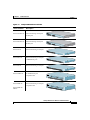
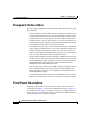
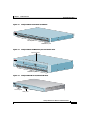
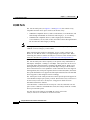
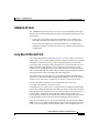
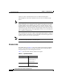
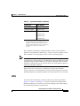
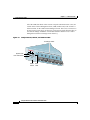
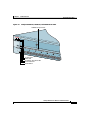
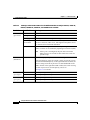
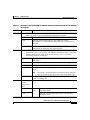
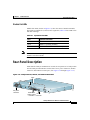
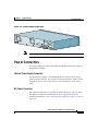
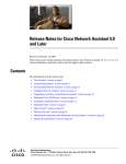
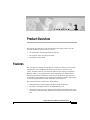
C H A P T E R
1
Product Overview
This chapter provides these topics that describe the Catalyst 2900 series XL
switches, hereafter referred to as the switches.
•
Switch features, including management options
•
Descriptions of the front and rear panels
•
Descriptions of the LEDs
Features
The switches are stackable 10/100 Ethernet switches to which you can connect
workstations, Cisco IP Phones, and other network devices such as servers,
routers, and other switches. The 2900 XL LRE switches employ Long-Reach
Ethernet (LRE), a very-high-data-rate digital subscriber line (VDSL)-based
technology that allows an Ethernet network to reach distances up to 4921 feet
(1500 meters). The switches can be deployed as backbone switches, aggregating
10/100 and Gigabit Ethernet traffic from other network devices.
The Catalyst 2900 XL switches have these features:
•
Autonegotiates speed and duplex operation on all 10/100 ports
•
Operates in full-duplex mode on all 100BASE-FX ports
•
Checks for errors on a received packet, determines the destination port, stores
the packet in shared memory, and then forwards the packet to the destination
port
Catalyst 2900 Series XL Hardware Installation Guide
78-6461-04
1-1
Chapter 1
Product Overview
Features
•
On the Catalyst 2924M XL, Catalyst 2912MF XL, and Catalyst 2924M XL
DC switches, two module slots for 10BASE-T/100BASE-TX, 1000BASE-X,
1000BASE-T, Gigabit Ethernet, and asynchronous transfer mode (ATM)
modules
•
On the Catalyst 2924M XL DC switch, a direct current (DC) power converter
•
On the Catalyst 2912 LRE XL and 2924 LRE XL switches, up to 24 LRE
ports through one RJ-21 connector and hot swapping capability with the
Cisco LRE customer premises equipment (CPE) devices
•
Supports up to 2048 MAC addresses on the Catalyst 2924 XL, 2924C XL, and
2912 XL switches
•
Supports up to 8192 MAC addresses on the Catalyst 2924M XL, Catalyst
2924M XL DC and Catalyst 2912MF XL switches
Figure 1-1 shows the switch models.
Catalyst 2900 Series XL Hardware Installation Guide
1-2
78-6461-04
Chapter 1
Product Overview
Features
Figure 1-1
Catalyst 2900 Series XL Switches
Version Number
Description
WS-C2912-LRE-XL
4 fixed autosensing 10/100 ports
12 LRE ports
WS-C2924-LRE-XL
WS-C2912-XL
INPUT
PWR
OUTPUT
PWR
RESET
9X
TEMP
10X
11X
FAN
12X
Cisco RPS
300
4 fixed autosensing 10/100 ports
24 LRE ports
INPUT
PWR
OUTPUT
PWR
RESET
9X
TEMP
10X
11X
FAN
12X
Cisco RPS
300
12 fixed autosensing 10/100 ports
1X
2X
3X
4X
MODE
5X
6X
7X
8X
10BaseT/
9X
100BASE
10X
-TX
11X
12X
Catalyst
WS-C2924C-XL
22 fixed autosensing 10/100 ports
2 100BASE-FX ports
1X
2X
3X
4X
MODE
5X
6X
7X
8X
2900
SERIES
XL
SERIES
XL
10BASE9X
T/100BAS
10X
E-TX
11X
12X
13X
14X
15X
16X
17X
Catalyst
18X
19X
20X
2900
100BAS
21X
22X
E-FX
23
24
WS-C2924-XL
24 fixed autosensing 10/100 ports
1X
2X
3X
4X
MODE
5X
6X
7X
8X
10BASE9X
10X
100BaseF
T/100BAS
E-TX X
11X
12X
13X
14X
16X
17X
Catalyst
18X
19X
20X
22X
WS-C2912MF-XL
12 100BASE-FX ports
2 expansion slots
1
2900
SERIES
XL
SERIES
XL
21X
23X
24X
2
Catalyst
1
2900
2
MODE
3
4
100BASE
5
-FX
6
7
8
9
10
11
12
24 fixed autosensing 10/100 ports
2 expansion slots
1
2
1X
WS-C2924M-XLEM-DC
MODE
Catalyst
2X
3X
4X
5X
6X
7X
8X
9X
100BaseF
10X
11X
12X
13X
2900
SERIES
XL
X
14X
15X
16X
17X
18X
19X
20X
74075
WS-C2924M-XL
21X
22X
23X
24X
Catalyst 2900 Series XL Hardware Installation Guide
78-6461-04
1-3
Chapter 1
Product Overview
Front-Panel Description
Management Interface Options
You can configure and monitor individual switches and switch clusters by using
these interfaces:
•
Cluster Management Suite (CMS)—CMS is a graphical user interface that
can be launched from anywhere in your network through a web browser such
as Netscape Communicator or Microsoft Internet Explorer. CMS is already
installed on the switch. Using CMS, you can fully configure and monitor a
standalone switch, a specific cluster member, or an entire switch cluster. You
can also display network topologies to gather link information and to display
switch images to modify switch- and port-level settings.
•
Command-line Interface (CLI)—The switch IOS CLI software is enhanced to
support desktop-switching features. You can fully configure and monitor the
switch and switch cluster members from the CLI. You can access the CLI
either by connecting your management station directly to the switch console
port or by using Telnet from a remote management station.
•
Simple network management protocol (SNMP)—SNMP provides a means to
monitor and control the switch and switch cluster members. You can manage
switch configuration settings, performance, security, and collect statistics by
using SNMP management applications such as CiscoWorks2000 LAN
Management Suite (LMS) and HP OpenView.
You can manage the switch from an SNMP-compatible management station
that is running platforms such as HP OpenView or SunNet Manager. The
switch supports a comprehensive set of MIB extensions and four Remote
Monitoring (RMON) groups.
For more information about CMS, the CLI, and SNMP refer to the Catalyst
2900 Series XL and Catalyst 3500 Series XL Software Configuration Guide.
Front-Panel Description
Depending on the model, the switch front panels can have up to twenty-four
10/100 ports (See Figure 1-2), up to twelve 100BASE-FX ports (See Figure 1-3),
two module slots (see Figure 1-3), and up to twenty-four Long-Reach Ethernet
ports (See Figure 1-4). All switches have a set of LEDs and a Mode button. This
section describes these front-panel components.
Catalyst 2900 Series XL Hardware Installation Guide
1-4
78-6461-04
Chapter 1
Product Overview
Front-Panel Description
1X
2X
Catalyst 2900 XL Front-Panel 10/100 Ports
3X
MODE
4X
5X
6X
7X
8X
52646
Figure 1-2
10BASE-T
9X
10X
100BaseF
/100BASE
-TX X
11X
12X
13X
14X
15X
16X
17X
Catalyst
18X
19X
20X
21X
2900
100BAS
SERIES
E-FX
22X
XL
23
24
10/100 ports
100BASE-FX ports
Figure 1-3
Catalyst 2900 XL 100BASE-FX ports and Module Slots
Expansion slots
2
Catalyst
1
2
MODE
2900
SERIES
XL
47286
1
3
4
100BASE
-FX
5
6
7
8
9
10
11
12
100BASE-FX ports
Figure 1-4
Catalyst 2900 LRE XL 10/100 and LRE Ports
INPUT
PWR
OUTPUT
PWR
TEMP
FAN
9X
10X
11X
12X
Catalys
t 2900 LR
E XL
48005
RESET
10/100 ports
LRE ports
Catalyst 2900 Series XL Hardware Installation Guide
78-6461-04
1-5
Chapter 1
Product Overview
Front-Panel Description
10/100 Ports
The 10/100 switch ports (see Figure 1-2 and Figure 1-4) can connect to any
compatible network device up to 328 feet (100 meters) away:
Note
•
10BASE-T-compatible devices, such as workstations, Cisco IP Phones, and
hubs through standard RJ-45 connectors and Category 3, 4, or 5 cabling
•
100BASE-TX-compatible devices, such as high-speed workstations,
Cisco IP Phones, servers, hubs, routers, and other switches through standard
RJ-45 connectors and Category 5 cabling
A Category 5 cable is required for 100BASE-TX traffic. A port operating at
10BASE-T can use Category 3 and 4 cables.
When connecting the switch to workstations, servers, routers, and Cisco IP
Phones, be sure that the cable is a straight-through, twisted-pair cable. When
connecting the switch to switches or hubs, use a crossover cable. Pinouts for the
cables are described in Appendix B, “Connectors and Cable Specifications.”
The 10/100 switch ports can be explicitly set to operate in any combination of
half duplex, full duplex, 10 Mbps, or 100 Mbps. These ports also can be set for
speed and duplex autonegotiation, compliant with IEEE 802.3U. When set for
autonegotiation, the port senses the speed and duplex settings of the attached
device and advertises its own capabilities. If the connected device also supports
autonegotiation, the switch port negotiates the best connection (that is, the fastest
line speed that both devices support and full-duplex transmission if the attached
device supports it) and configures itself accordingly.
The 10/100 ports on the Catalyst 2900 XL switches provide protocol support for
Cisco IP Phones and per-port priority override. Refer to the Catalyst 2900 Series
XL and Catalyst 3500 Series XL Software Configuration Guide for more
information about these features.
Cisco IP Phones—connected to the 10/100 port—must be connected to an AC
power source. Unlike the 3524-PWR XL switch, the Catalyst 2900 XL switches
do not provide inline power.
For more info on the Catalyst 3524-PWR XL switch, refer to the
Catalyst 3500 Series XL Hardware Installation Guide.
Catalyst 2900 Series XL Hardware Installation Guide
1-6
78-6461-04
Chapter 1
Product Overview
Front-Panel Description
100BASE-FX Ports
The 100BASE-FX ports use 50/125- or 62.5/125-micron multimode fiber-optic
cabling. The connection distances between the switch and the attached device can
be as follows:
•
If the switch port and the port on the attached device are configured for
half-duplex operation, the connection can be up to 1352 feet (412 meters).
•
If the switch port and the port on the attached device are configured for
full-duplex operation, the connection can be over distances of up to 6562 feet
(2 kilometers).
Long-Reach Ethernet Ports
The Long-Reach Ethernet (LRE) ports (Figure 1-4) use one RJ-21 connector to
connect up to 24 Cisco LRE customer premises equipment (CPE) devices though
structured or unstructured wiring, such as existing telephone lines. The link
between the LRE switch port and each CPE device can reach speeds of up to 15
Mbps (full duplex) and distances of up to 4921 feet (1500 meters). You can
connect Cisco 575 LRE CPE and Cisco 585 LRE CPE devices to LRE ports on the
same Catalyst 2900 LRE XL switch, and you can hot swap the CPE devices without
powering down the switch or disrupting the other switch ports.
The default mode for each LRE port is speed autonegotiation and half-duplex
operation. For information about configuring the LRE ports, refer to the Catalyst
2900 Series XL and Catalyst 3500 Series XL Software Configuration Guide.
For more information about the Cisco LRE CPE devices, refer to the
Cisco LRE CPE Hardware Installation Guide.
If telephone services, such as voice or integrated services digital network (ISDN),
use the same cabling as LRE traffic, the LRE port must be connected to the patch
panel through a basic telephone service, also known as plain old telephone service
(POTS) splitter. The splitter routes LRE data (high-frequency) and voice
(low-frequency) traffic from the telephone line to the switch and private branch
exchange (PBX) switch or Public-Switched Telephone Network (PSTN).
If the other telephone services are connected through a private branch exchange
(PBX) switch, a Cisco LRE 48 POTS Splitter can be used. The PBX routes voice
traffic to private telephone networks and the public system telephone network
Catalyst 2900 Series XL Hardware Installation Guide
78-6461-04
1-7
Chapter 1
Product Overview
Front-Panel Description
(PSTN). For more information about the Cisco LRE 48 POTS Splitter
(PS-1M-LRE-48), refer to the Installation Notes for the Cisco LRE 48 POTS
Splitter.
Note
Cisco Long-Reach Ethernet (LRE) products are designed to share lines with
analog, Integrated Services Digital Network (ISDN), and digital private branch
exchange (PBX) switch telephones that use the 0 to 700 kHz frequency range.
Digital telephones connected to digital PBX switches that use frequencies above
700 kHz do not work when sharing a line with LRE signals. Due to the proprietary
nature of digital PBX switches, some digital PBX switch services use frequencies
above 700 kHz. [CSCdu73260]
If the installation does not have a PBX, a homologated POTS splitter is required
to directly connect to the PSTN. For more information about homologated POTS
splitters, contact your Cisco sales representative.
Note
If a connection to a telephone network is not required, a splitter is not needed, and
the switch can connect directly to the patch panel.
Module Slots
The module slots (see Figure 1-2) are for the Catalyst 2900 XL hot-swappable
modules. Each module port is internally switched to other switch ports and is
managed through the switch management interfaces.
Table 1-1 lists the modules that the module slots support.
Table 1-1
Expansion Modules
Module Type
Model Number
10/100 Ethernet
WS-X2914-XL
WS-X2914-XL-V
WS-X2922-XL
100 BASE-FX
WS-X2922-XL-V
WS-X2924-XL-V
Catalyst 2900 Series XL Hardware Installation Guide
1-8
78-6461-04
Chapter 1
Product Overview
Front-Panel Description
Table 1-1
Expansion Modules (continued)
Module Type
Model Number
1000BASE-T
WS-X2932-XL
1Ethernet
WS-X2931-XL
ATM
Gigabit
WS-X2971-XL
WS-X2972-XL
WS-X2951-XL
WS-X2961-XL
1. The Ethernet Gigabit module supports several
Gigabit Interface Converter (GBIC) devices. For a
complete list and the minimum software release
required, refer to the Release Notes for the Catalyst
2900 Series XL and Catalyst 3500 Series XL
Switches.
These modules automatically configure themselves when you insert them in
module slots and tighten the thumb screws. A power-on self-test (POST) verifies
that the module is working properly before it starts forwarding packets.
Note
Modules WS-X2914-XL and WS-X2922-XL support 2048 MAC addresses. If
you install one of these modules in a 2924M XL or Catalyst 2912MF XL switch
(both supporting 8192 MAC addresses), the module fails POST. You can start the
module by restarting that switch. After the restart, the switch address capacity is
reduced to 2048 MAC addresses.
Refer to the Catalyst 2900 Series XL Modules Installation Guide and the
Catalyst 2900 Series XL ATM Modules Installation and Configuration Guide for
detailed information on expansion modules for Catalyst 2900 series XL switches.
LEDs
You can use the switch LEDs to monitor switch activity and its performance.
Figure 1-5, Figure 1-6, and Figure 1-7 show the location of the LEDs and the
Mode button that you use to select a port mode. Changing a port mode changes
the information provided by each port LED.
Catalyst 2900 Series XL Hardware Installation Guide
78-6461-04
1-9
Chapter 1
Product Overview
Front-Panel Description
All of the LEDs described in this section except the utilization meter (UTL) are
visible on the Cluster Management Suite (CMS) window and, if the switch is a
cluster member, on the CMS Cluster Manager window. The Catalyst 2900 Series
XL and Catalyst 3500 Series XL Software Configuration Guide describes how to
use CMS to manage standalone or individual switches and how to use cluster
management software to manage switch clusters].
Figure 1-5
Catalyst 2912 XL, 2924 XL, and 2924C XL LEDs
10/100 port LEDs
1X
2X
3X
MODE
Mode
button
RPS
LED
4X
5X
6X
7X
47288
System LED
Port mode LEDs
Catalyst 2900 Series XL Hardware Installation Guide
1-10
78-6461-04
Chapter 1
Product Overview
Front-Panel Description
Figure 1-6
Catalyst 2912MF XL, 2924M XL, and 2924M XL DC LEDs
10BASE-FX port LEDs
1
2
1
2
MODE
3
4
100BAS
E-FX
5
6
48003
7
System LED
RPS LED
Expansion slot status LED
Port mode LED
Mode button
Catalyst 2900 Series XL Hardware Installation Guide
78-6461-04
1-11
Chapter 1
Product Overview
Front-Panel Description
Figure 1-7
Catalyst 2912 LRE XL and 2924 LRE XL LEDs
10/100 port LEDs
SYSTEM
RPS
1X
LRE
STAT
DUPLX
SPEED
Mode
button
2X
3X
4X
System LED
RPS LED
LRE LED
STAT LED
DUPLEX LED
Speed LED
48002
MODE
LRE port LEDs 1-12
LRE port LEDs 13-24
System LED
The system LED shows whether the system is receiving power and functioning
properly. Table 1-2 lists the LED colors and their meanings.
Table 1-2
System LED
Color
System Status
Off
System is not powered up.
Green
System is operating normally.
Amber
System is receiving power but is not functioning properly.
For information on the System LED colors during POST, see the “Powering On
the Switch and Running POST” section on page 2-24.
Catalyst 2900 Series XL Hardware Installation Guide
1-12
78-6461-04
Chapter 1
Product Overview
Front-Panel Description
RPS LED
The Catalyst 2912 LRE XL and Catalyst 2924 LRE XL switches use the Cisco
RPS 300 (model PWR300-AC-RPS-N1). All other Catalyst 2900 XL and
Catalyst 3500 XL switches use the Cisco RPS 600 (model PWR600-AC-RPS).
Refer to the appropriate switch documentation for redundant power system (RPS)
descriptions specific for the switch. Table 1-2 and Table 1-3 list the RPS LED
colors and their meanings.
Figure 1-8
RPS LED on the Catalyst 2912 XL, 2924C XL, 2924 XL, 2924MF XL, 2924M XL, and
2924M XL DC Switches
Color
RPS Status
Off
RPS is off or is not installed.
Green
RPS is operational.
Blinking green
The RPS and the switch AC power supply are both powered up. If the switch power
supply fails, the switch powers down and after 15 seconds restarts, using power
from the RPS. The switch goes through its normal boot sequence when it restarts.
Note
Amber
Table 1-3
This is not a recommended configuration. For more information see the
“Cisco RPS Connector” section on page 1-22.
RPS is connected but not functioning.
•
The RPS could be in standby mode. Pressing the Mode button on the RPS puts
it in Ready mode, and the LED should turn green.
•
One of the power supplies in the RPS could have failed.
•
The fan in the RPS might have failed.
RPS LED on the Catalyst 2912 LRE XL and 2924 LRE XL Switches
Color
RPS Status
Off
RPS is off or not properly connected.
Solid green
RPS is connected and ready to provide back-up power, if required.
Blinking green
RPS is connected but is unavailable because it is providing power to another device
(redundancy has been allocated to a neighboring device).
Catalyst 2900 Series XL Hardware Installation Guide
78-6461-04
1-13
Chapter 1
Product Overview
Front-Panel Description
Table 1-3
RPS LED on the Catalyst 2912 LRE XL and 2924 LRE XL Switches (continued)
Color
RPS Status
Solid amber
The RPS is in standby mode or in a fault condition. Press the Standby/Active button
on the RPS, and the LED should turn green. If it does not, the RPS fan could have
failed. Contact Cisco Systems.
Blinking amber
The internal power supply in a switch has failed, and the RPS is providing power
to the switch (redundancy has been allocated to this device).
Port LEDs and Modes
Each of the 10/100, 100BASE-FX, and LRE ports and module slots have a port
LED. These port LEDs, as a group or individually, display information about the
switch and about the individual ports. The port modes (Table 1-4 and Table 1-5)
determine the type of information displayed.
To select or change a mode, press the Mode button until the desired mode is
highlighted. When you change port modes, the meaning of the port LED colors
also changes. Table 1-6 and Table 1-7 list the port LED colors.
Table 1-4
Port Mode LEDs on the Catalyst 2912 XL, 2924C XL, 2924 XL, 2924MF XL, 2924M XL, and
2924M XL DC Switches
Mode LED
Port Mode
Description
STAT
Port status
The port status. This is the default mode.
UTL
Switch utilization
The current bandwidth in use by the switch. (See Figure 1-8.)
FDUP
Port duplex mode
The port duplex mode: full duplex or half duplex, and default
modes:
100
Port speed
•
10/100 ports: auto
•
100BaseFX ports: auto
•
Gigabit ports: auto
The port operating speed: 10 or 100 Mbps.
Catalyst 2900 Series XL Hardware Installation Guide
1-14
78-6461-04
Chapter 1
Product Overview
Front-Panel Description
Table 1-5
Port Mode LEDs on Catalyst 2912 LRE XL and 2924 LRE XL Switches
Mode LED
Port Mode
Description
LRE
LRE link status
Long-Reach Ethernet (LRE) link status of the LRE ports on the
Catalyst 2912 LRE XL and Catalyst 2924 LRE XL switches.
Default mode on these switches only.
Note
STAT
Port status
When the LRE mode is active, the 10/100 switch ports
on the Catalyst 2912 LRE XL and
Catalyst 2924 LRE XL continue to show Ethernet link
status.
Ethernet link status of the 10/100 or 100BASE-FX switch ports
or the Ethernet link status on the remote CPE.
Default mode on all Catalyst 2900 XL and Catalyst 3500 XL
switches except the Catalyst 2912 LRE XL and
Catalyst 2924 LRE XL switches.
DUPLX
Port duplex mode
The port duplex mode: full duplex or half duplex. The default
setting is half duplex.
SPEED
Port speed
The port operating speed: 10 or 100 Mbps. The default setting
is auto.
Catalyst 2900 Series XL Hardware Installation Guide
78-6461-04
1-15
Chapter 1
Product Overview
Front-Panel Description
Table 1-6
Meanings of Port Status LED Colors for Different Modes on Catalyst 2912 XL, 2924C XL,
2924 XL, 2924MF XL, 2924M XL, and 2924M XL DC Switches
Port Mode
Port LED Color
Meaning
STAT
(port status)
Off
No link.
Solid green
Link present.
Flashing green
Activity. Port is transmitting or receiving data.
Alternating
green-amber
Link fault. Error frames can affect connectivity, and errors such as
excessive collisions, CRC errors, and alignment and jabber errors
are monitored for a link-fault indication.
Solid amber
Port is not forwarding. Port was disabled by management or an
address violation or was blocked by Spanning Tree Protocol (STP).
Note
UTL
(utilization)
Green
After a port is reconfigured, the port LED can remain
amber for up to 30 seconds as STP checks the switch for
possible loops.
The LEDs display backplane utilization on a logarithmic scale.
If all port LEDs are green, the switch is using 50 percent or more
of its total bandwidth capacity. If the right-most LED is amber, the
switch is using less than 50 percent of its total bandwidth. If the
LED to the left of the right-most LED is amber, the switch is using
less than 25 percent of its total capacity, and so on.
See Figure 1-8 for details.
FDUP
Off
Port is operating in half duplex.
(port duplex)
Green
Port is operating in full duplex.
100
(port speed)
Off
Port is operating at 10 Mbps.
Green
Port is operating at 100 Mbps.
Catalyst 2900 Series XL Hardware Installation Guide
1-16
78-6461-04
Chapter 1
Product Overview
Front-Panel Description
Table 1-7
Meanings of Port Status LEDs for Different Modes on Catalyst 2912 LRE XL and 2924 LRE
XL Switches
Port Mode
Port LED Color
LRE
Note
STAT
Description
In LRE mode, the 10/100 switch port LEDs continue to reflect Ethernet link
status. See Table 1-5 for LED information about the 10/100 ports.
Cyan (off)
No LRE link present on the LRE port.
Green
LRE link present on the LRE port. Port LED turns green in
approximately 10 seconds after the LRE port detects a connection to a
LRE CPE.
Amber
LRE port on the switch and WALL port on the LRE CPE unable to
establish the rate defined by the assigned profile.
Note
In STAT mode, the LRE ports reflect the Ethernet link between the remote CPE
and an Ethernet device such as a PC. The Ethernet link default settings on the LRE
ports are different from those on the 10/100 ports. See Table 1-5 for LED
information about the 10/100 ports.
Cyan (off)
No LRE link present on the LRE port, or the port is administratively
shut down.
Green
LRE link present on the LRE port. Port is in STP forwarding state.
Blinking green
Activity on the LRE port. Port is sending or receiving data.
Amber
LRE port is in a non-STP forwarding state or is administratively shut
down.
Note
DUPLX
After a port is reconfigured, the port LED can remain amber for
up to 30 seconds as STP checks the switch for possible loops.
Blinking amber
Activity on the LRE port. Port is sending or receiving data, but it is not
in STP forwarding state.
Cisco IOS
Release
12.0(5.x)WC1/
WC21
Cisco IOS Release 12.0(5.x)WC42 3
Cyan (off)
Cyan
(off)
Green
LRE port or remote CPE Ethernet port is operating in
half-duplex mode.
LRE port or remote CPE Ethernet port is operating in
full-duplex mode.
Catalyst 2900 Series XL Hardware Installation Guide
78-6461-04
1-17
Chapter 1
Product Overview
Front-Panel Description
Table 1-7
Meanings of Port Status LEDs for Different Modes on Catalyst 2912 LRE XL and 2924 LRE
XL Switches (continued)
Port Mode
Port LED Color
Description
SPEED
Cisco IOS
Release
12.0(5.x)WC1/
WC21
Cisco IOS Release 12.0(5.x)WC42 3
Cyan (off)
Cyan
(off)
LRE port or remote CPE Ethernet port is operating at
10 Mbps.
Green
LRE port or remote CPE Ethernet port is operating at
100 Mbps.
1. The LEDs on Catalyst 2900 LRE XL switches with Cisco IOS Release 12.0(5.x)WC1 or Cisco IOS Release 12.0(5.x)WC2
provide information about the connected Cisco 575 LRE CPE devices. These IOS releases do not support the Cisco 585 LRE
CPE devices.
2. The Catalyst 2900 LRE XL switches do not support Cisco IOS Release 12.0(5.x)WC3.
3. The LEDs on Catalyst 2900 LRE XL switches with Cisco IOS Release 12.0(5.x)WC4 or later do not provide information
about any connected LRE CPE devices. To verify the LRE CPE Ethernet link status from a switch with this release or higher,
use the Port Settings window or the show remote interfaces status user EXEC command.
Figure 1-9 shows bandwidth utilization percentages displayed by the right-most
LEDs.
Figure 1-9
Bandwidth Utilization
Catalyst 2900 SERIES XL
10BaseT/100BaseTx
RPS
1x
2x
3x
4x
5x
6x
7x
8x
9x
10x
11x
12x
MODE
47293
SYSTEM
6.25 –12.4%+
12.5 –24%+
25 – 49%+
50%+
Catalyst 2900 Series XL Hardware Installation Guide
1-18
78-6461-04
Chapter 1
Product Overview
Rear-Panel Description
Module Slot LEDs
Module slot LEDs (shown in Figure 1-6) show the status of installed modules.
The LEDs are numbered 1 (left slot) and 2 (right slot). Table 1-8 lists LED colors
and their meanings.
Table 1-8
Note
Expansion Slot LEDs
Color
Expansion Slot Status
Off
No module is installed.
Green
Module is operating normally.
Amber
Module failed POST and should be replaced.
For the default LED settings for modules, refer to the Catalyst 2900 Series XL
Modules Installation Guide.
Rear-Panel Description
Other than the Catalyst 2924M XL DC switch, the rear panels of a Catalyst 2900
XL and Catalyst 2900 LRE XL switches have an AC power connector, an RPS
connector, and an RJ-45 console port. (See Figure 1-10 through Figure 1-12.)
Figure 1-10 Catalyst 2912 XL, 2924 XL, and 2924C XL Rear Panel
Fans
RATING
100-127/
200-240V~
1.0A/O.5
A 50-8
0HZ
DC INPU
TS FOR
REMOTE
POWER
SUPPLY
SPECIFI
ED IN
+5V
MANUAL
@9A, +12V
@0.5A
CONSOL
AC power
connector
47295
E
Redundant
power system RJ-45
connector connector
Catalyst 2900 Series XL Hardware Installation Guide
78-6461-04
1-19
Chapter 1
Product Overview
Rear-Panel Description
Figure 1-11 Catalyst 2912 LRE XL, and 2924 LRE XL Rear Panel
100-240
MAXIMU
M 300
W
TOTAL
OUTPUT
48004
V~
5-3A
50/60Hz
DC OUT
PUT
AC power
connector
CONSOL
E
Redundant
power system
connector
RJ-45
connector
Figure 1-12 Catalyst 2924M XL and 2912 MF XL Rear Panel
Fans
CONSOL
DC INP
UTS FOR
REMOTE
POWER
SUPPLY
SPECIF
IED IN
+5V
@9A, +12 MANUAL
V
@0.5A
RJ-45
connector
RATING
100-120
/200-240 ~
2.0A/1.0
V
A 50-6
0HZ
DC INP
UT
Redundant
power system
connector
47296
E
AC power
connector
The rear panel of the Catalyst 2924M XL DC switch has a DC power connector
(also referred to as the terminal block header), an RJ-45 console port, and a
ground lug. (See Figure 1-13.) The switch is shipped with a terminal block plug
in the DC power connector.
Catalyst 2900 Series XL Hardware Installation Guide
1-20
78-6461-04
Chapter 1
Product Overview
Power Connectors
CONSOL
E
INPUT:
36
CURREN - 72
T: 4-2A
A
B
+ + -
REFER
BEFORE TO MANUAL
CONNEC
POWER TING
74070
Figure 1-13 Catalyst 2924M XL Rear Panel
DC INP
UT
Note
The Cisco RPS does not support the Catalyst 2924M XL DC switch.
Power Connectors
You can provide power to the switch either through the internal power supply or
through the Cisco RPS.
Internal Power Supply Connector
The internal power supply is an autoranging unit that supports input voltages
between 100 and 240 VAC. If you plan to use the internal power supply, use the
supplied AC power cord to connect the AC power connector to an AC power
outlet.
DC Power Connector
The Catalyst 2924M XL DC switch has an internal DC-power converter. It has
dual feeds (A and B) that are diode-OR-ed into a single power block. For
installation instructions, see the “Wiring the DC-Input Power Source” section on
page 2-29.
Catalyst 2900 Series XL Hardware Installation Guide
78-6461-04
1-21
Chapter 1
Product Overview
Power Connectors
Caution
You must connect the Catalyst 2924M XL DC switch only to a DC-input power
source that has an input supply voltage from -36 to -72 VDC. If the supply voltage
is not in this range, the switch might not operate properly or might be damaged.
Cisco RPS Connector
Specific Cisco RPS models support specific Catalyst 2900 XL switches:
Note
•
Cisco RPS 600 (model PWR600-AC-RPS)—supports the Catalyst 2912 XL,
2924C XL, 2924 XL, 2924MF XL, and 2924M XL switches.
•
Cisco RPS 300 (model PWR300-AC-RPS-N1)—supports the Catalyst
2912 LRE XL and 2924 LRE XL switches
The Cisco RPS does not support the Catalyst 2924M XL DC switch.
RPS Connector on the Catalyst 2912 XL, 2924C XL, 2924 XL, 2924MF XL, and 2924M XL Switches
The Cisco RPS 600 (model PWR600-AC-RPS) provides a quasi-redundant power
source for four external devices that use up to 150W DC each. Use a one-to-one
cable (one connector at each cable end) to connect four external devices to the
four DC output power modules. The power source is quasi-redundant because
there are two AC input power modules for the Cisco RPS and one DC output
power module for each external device. The AC input to the Cisco RPS is fully
redundant, but the DC output to the external devices is not.
Warning
Attach only the Cisco RPS (model PWR600-AC-RPS) to the RPS 600 receptacle.
Note
Do not connect the switch power cord to an AC outlet if the switch is also
connected to a powered-on RPS. The switches do not support the fully-redundant
configuration described in the RPS documentation. We do not recommend the
redundant-with-reboot configuration.
For more information on the Cisco RPS 600, refer to the Cisco Redundant Power
System Hardware Installation Guide.
Catalyst 2900 Series XL Hardware Installation Guide
1-22
78-6461-04
Chapter 1
Product Overview
Power Connectors
RPS Connector on the Catalyst 2912 LRE and 2924 LRE XL Switches
The RPS is a 300W redundant power system that can support six external network
devices and provides power to one failed device at a time. It automatically senses
when the power supply of a connected device fails and provides the necessary
power to the failed device to prevent loss of network traffic. When the device
internal power supply has been brought up or replaced, the RPS automatically
stops powering the device.
Warning
Note
Attach only the Cisco RPS (model PWR300-AC-RPS-N1) to the RPS 300
receptacle.
The RPS can only power one switch at a time. If more than one switch fails at the
same time, any subsequent switch is not supported by the RPS until the first
switch failure is resolved.
For more information on the Cisco RPS 300, refer to the Cisco Redundant Power
System 300 Hardware Installation Guide.
Console Port
You can connect a switch to a PC through the switch console port and by using
the supplied rollover cable and DB-9 adapter. You need to provide a
RJ-45-to-DB-25 female DTE adapter to connect the switch console port to a
terminal. You can order a kit (part number ACS-DSBUASYN=) containing that
adapter from Cisco. For console port and adapter pinout information, see the
“Connecting to the Console Port” section on page 2-42.
Catalyst 2900 Series XL Hardware Installation Guide
78-6461-04
1-23
Chapter 1
Product Overview
Power Connectors
Catalyst 2900 Series XL Hardware Installation Guide
1-24
78-6461-04